In a “load/unload” gold heap leach operation, the time that a heap is on the reusable leach pad is of critical economic importance. The turnover of heaps must flow in a consistent and cyclic manner in order to leach the gold bearing ore in an economically feasible manner. The process cycle is time dependent on two main stages, leaching and neutralizing. During the leaching stage, an alkaline solution containing cyanide is sprayed over a heap to extract the precious metals from the ore. After the precious metals have been extracted from the ore, the remaining cyanide must be rinsed from the heap in a neutralization phase. The cyanide is rinsed from the ore and detoxified with hydrogen peroxide using copper sulfate as a catalyst for the reaction. A prolonged neutralization stage interrupts the continuity of the process cycle and becomes the limiting factor in heap turnover time. Therefore, an understanding of the neutralization processes can be beneficial in expediting neutralization, while ensuring an environmentally safe level of weak acid dissociable (wad) cyanide prior to the unloading of spent ore.
Methods and Materials
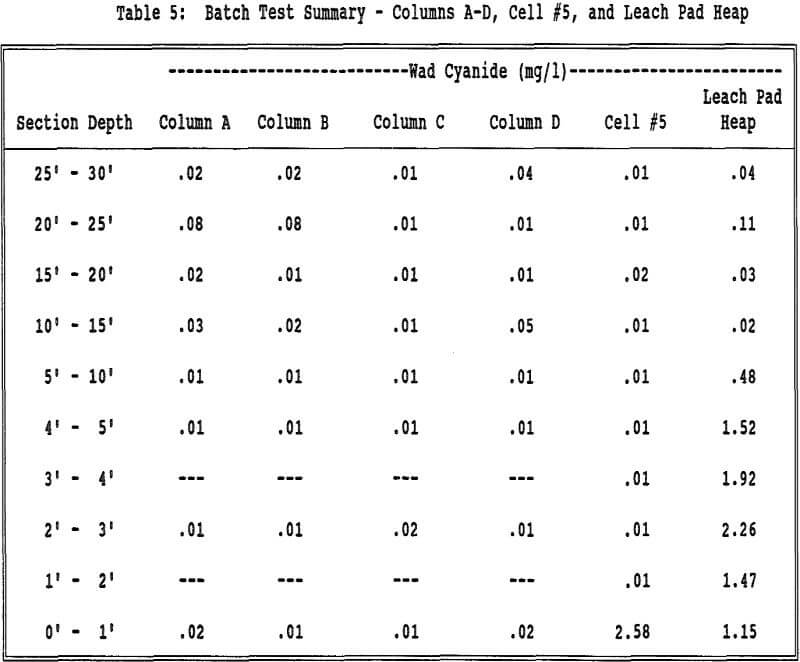
During the off-loading of an actual leach pad, spent ore samples were collected from 5 ft sections extending from 5 to 30 feet, and from 1 ft sections extending from the base of the heap up to 5 feet. The five uppermost samples were collected by first exposing a 5 ft bench in the spent ore and then removing a vertical composite from the exposed bench.
Four 29 ft (8.839 m) long, 10 inch (0.254 m) diameter columns were constructed from white PVC pipe and connected with 12 bolt PVC flanges with rubber gaskets. The bottom section had a 12 inch sight glass and two screens on the bottom, a 1 inch heavy screen covered with a 40 mesh screen. The columns sat on a metal plate, six inches off the floor. A 1 inch black steel pipe, with a 3/8 inch reducer and ball valve, extended from the bottom of the column.
The ore in each column was leached for 60 days, the average of actual operating conditions, with 0.5 lb per ton sodium cyanide (NaCN) barren solution at an application rate of 0.0040 gpm per sq ft (0.159 L per min per sq m), to mimic field conditions.
The columns were allowed to drain for three days at the end of the neutralization period and then were unloaded a section at a time. Samples were removed from each section with a post hole digger and collected in plastic lined 5 gal buckets. For sections 2-6, the second bucket of material (from the top of each section) was removed and saved for size fraction and moisture analyses.
Results and Discussion
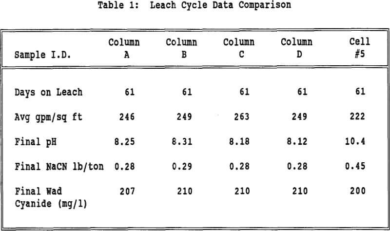
Each column and Cell 5 were leached for 61 days at a constant flow rate. The pH of the columns was consistently lower than that of Cell 5 presumably due to the amount of lime in the original crushed ore. The NaCN (lb per ton) levels also stayed consistently lower for the columns compared to Cell 5 probably due to increased cyanide volatilization.
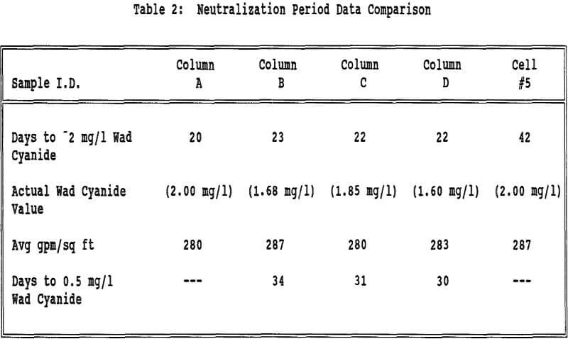
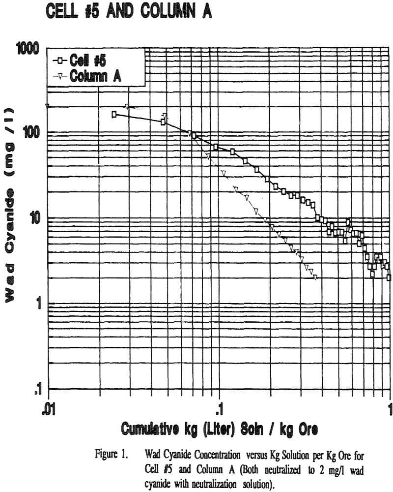
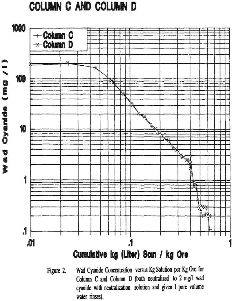
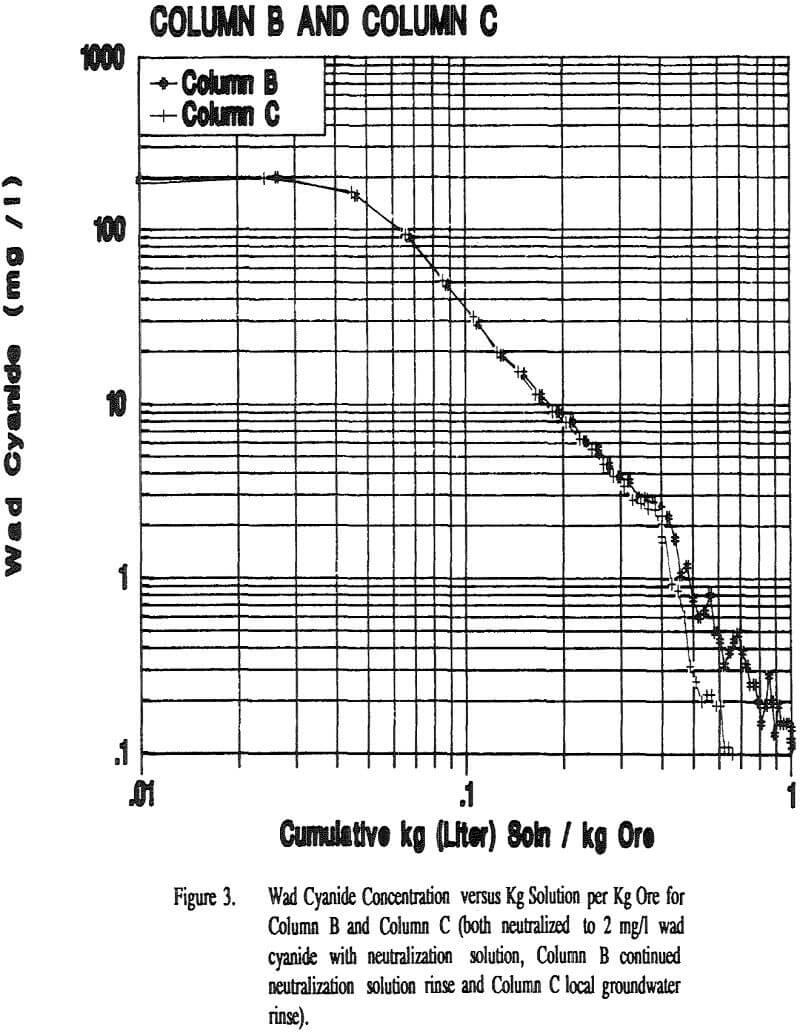
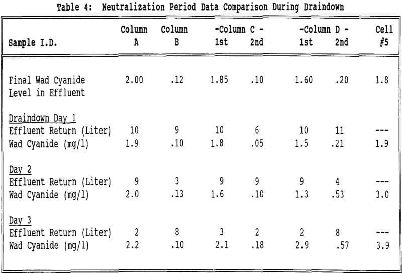
The flow rates were relatively constant for all of the columns and Cell 5. All columns took about the same amount of time to reach 2 mg/l wad cyanide. Cell 5 took approximately twice as long to reach this same wad cyanide concentration. Column C and Column D both had water rinses after the 2 mg/l wad cyanide level was reached. These columns took about the same amount of time to go from 2 mg/l to 0.5 mg/l wad cyanide.
The lower pH in the groundwater (pH = 5.6) versus the neutralization solution (pH = 8.6) may also be a factor in the differences between the two rinse procedures as cyanide volatilization will be enhanced at the lower pH.
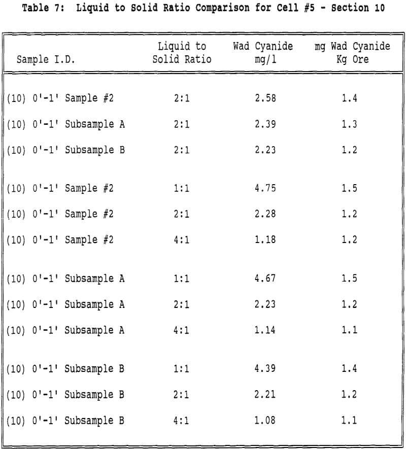
Displacement appears to play a part in the rinsing of a heap or column. If the mechanism of rinsing were strict displacement, the cyanide concentration in the effluent would remain constant until the cyanide was displaced and the concentration decreased to zero. However the cyanide concentration decreases steadily from the beginning of the neutralization period, indicating that dilution is taking place.
Generally the cyanide concentration increases slightly as the solution volume decreases, indicating that the mechanism of cyanide removal is dilution.
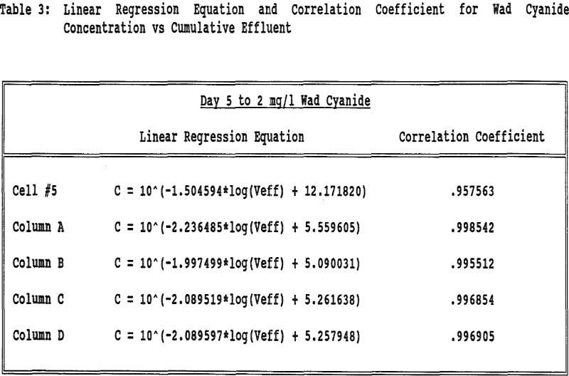
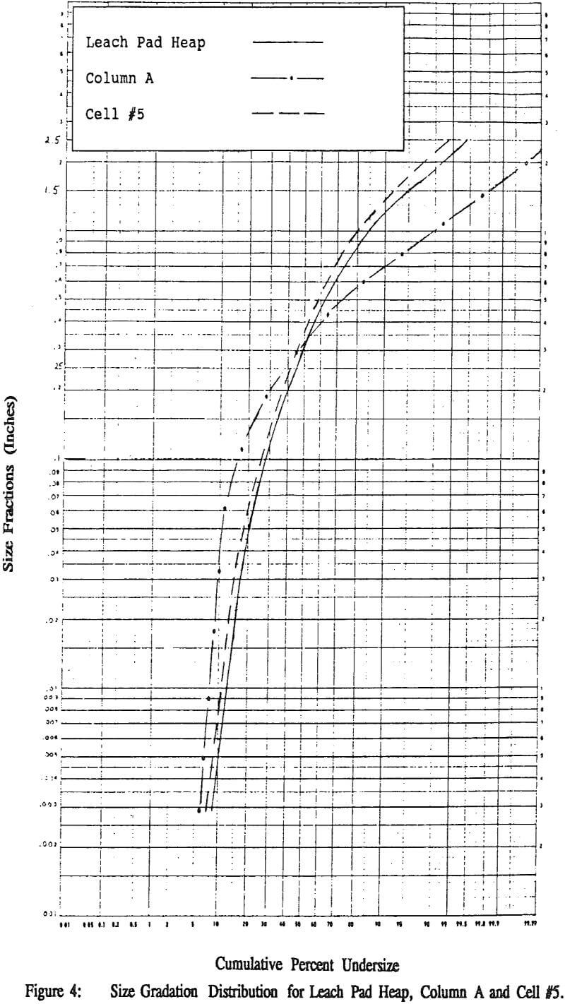
While the heaps do not have the same mean particle size (d50), nonetheless they are distributed similarly around the mean as evidenced by the similar slopes. Column A shows a different distribution although the overall mean particle size is very similar to the heaps.
The difference in the heaps can be explained from the difference in their neutralization treatments. The “Leach Pad Heap” was neutralized in the winter months with spray wobblers covered with cups. The cups cause direct channeling into the heap and do not allow even coverage of the surface of the heap.
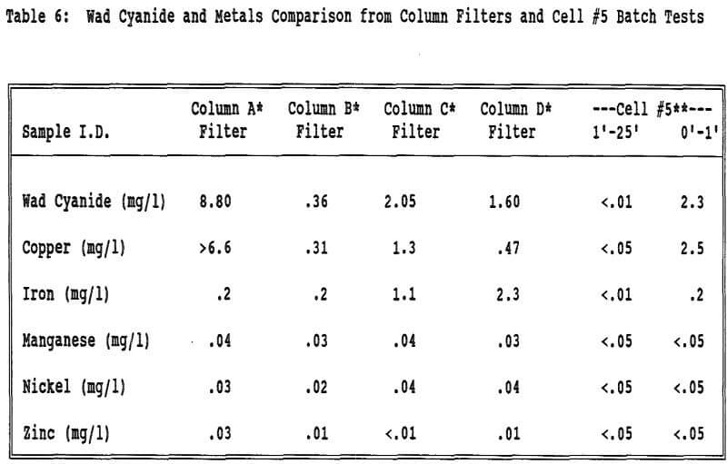
Wad cyanide was detected in the material on the geotextile filters that covered the screens at the bottom of the columns to avoid the loss of fine particulate material during the leach and neutralization cycles. Approximately 20 grams of fines adhered to each of the saturated filters.
Even though migration of fines does not appear to be an appreciable factor from the screen gradation data, the fines in the very lowest part of the column or heap appear to be contributing to the elevated wad cyanide values in the effluent. The filter and trace metal data indicate that fines are collecting at the base of the columns (and most likely the heaps) and holding the enhanced levels of wad cyanide.
Summary and Conclusions
Solid sampling is more indicative of heap neutralization than effluent sampling at BMC. The bottom layer of ore, in the case of the columns of the geotextile filter, is continuously saturated with relatively high concentrations of cyanide bearing solution. It appears that fines collect in this bottom layer. Having continuous contact with the cyanide solution, the fines may indeed adsorb cyanide on their high surface area. The cyanide slowly diffuses from this saturated zone, never being thoroughly flushed, and causes elevated cyanide levels in the effluent, but is not indicative of the porewater in the neutralized spent ore above this layer. The enhanced cyanide levels during draindown appear to be coming from these cyanide enriched fines, the cyanide being in the form of wad copper cyanide complexes.
