Table of Contents
The development of larger size flotation machines, which started in the 1950’s and 1960’s, is still proceeding. The largest mechanical flotation machines available today have unit volumes in the range of 38 to 42 m³ (1,350 to 1,500 cft). In fact, the motivating forces of increasing capital and energy costs and decreasing ore grades, which created the need for large flotation cells, not only still exist, but are becoming more critical.
The development of the Dorr-Oliver Flotation machine was initiated as a result of an industry need for more efficient mechanical flotation performance. The cost pressures facing the minerals industry today are severe and result from a variety of factors including:
a) Low product demand and depressed prices
b) Older process equipment with low energy efficiency
c) Poor productivity
d) High labor costs
e) Falling ore grades
Design Considerations
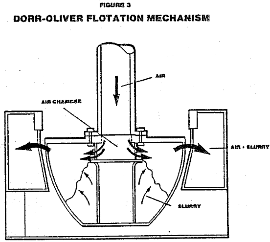
The purpose of the rotor in a mechanical flotation cell is two-fold. First, it must perform the task of a pump in maintaining the suspension of solids throughout the lower portions of the tank. Second, it must produce the required quantity of fine air bubbles and effectively disperse them into the slurry.
The guidelines called for a small diameter energy efficient rotor that would operate as an efficient pump and air disperser. It was also important for the mechanism to be able to restart after shutdown under load. Finally the rotor should have a long (2-3 year) service life.
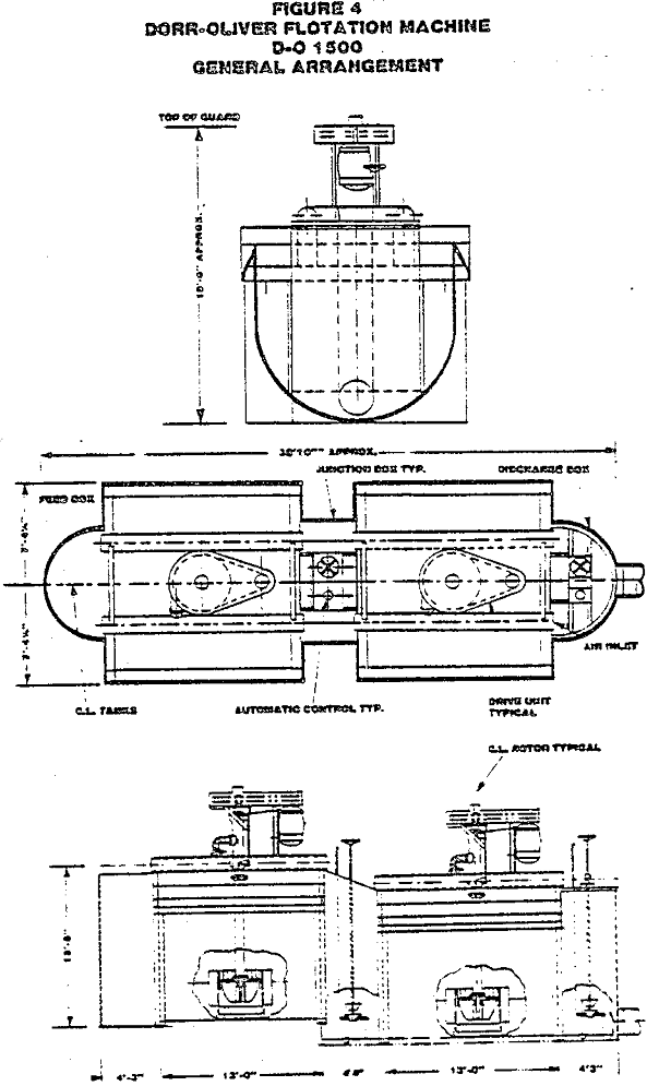
The cell tank design should aid the flow of the coarser solid particles toward the mechanism to assist in re-suspension. In the Dorr-Oliver design, the slurry is drawn across the tank bottom into the rotor, lifted and then expelled radially from the upper region of the rotor. A tank design which is markedly truncated or rounded at the bottom is therefore desirable. A full semi-circular section tank bottom design was selected. A modified cell to cell flow concept was adopted by the use of full depth partition plates between each mechanism. Slurry transfer occurs via an opening at the bottom of this partition which reduces both pulp and froth “short circuiting” in a series of cells. The semi-circular design is not subject to bulging forces encountered in rectangular section tanks which require thicker steel plate without contributing substantially to tank life.
Development Programs
The complete development program involved three phases. The first two involved the appraisal of mechanical and physical performance parameters obtained from testing prototype designs at full scale production size. The third phase involved the process performance testing of the chosen prototype design selected from the results of the first two phases.
Phase One – Design, manufacture and testing of a 2.8 m³ (100 ft³) cell mechanism
Phase Two – Design, manufacture and testing of a 38 – 42 m³ (1350- 1500 ft³) flotation cell mechanism.
Phase Three – Process Testing of the Selected Mechanism
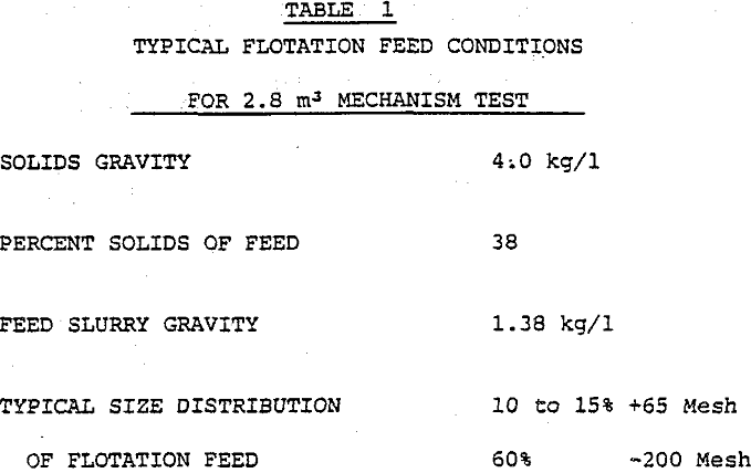
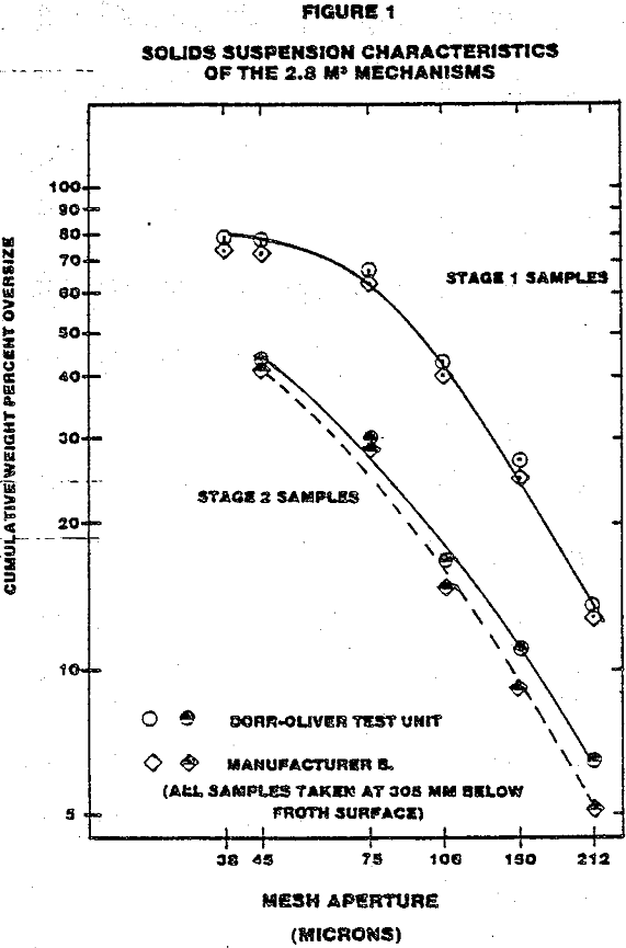
Initial testing to define the stator design parameters was done using two prototype mechanisms for 2.8 m³ cells. The test was run in a copper mill in the Southwestern United States, where the test units were installed in the first two of a six cell rougher scavenger bank. The last four mechanisms in this group were a different design (type B).
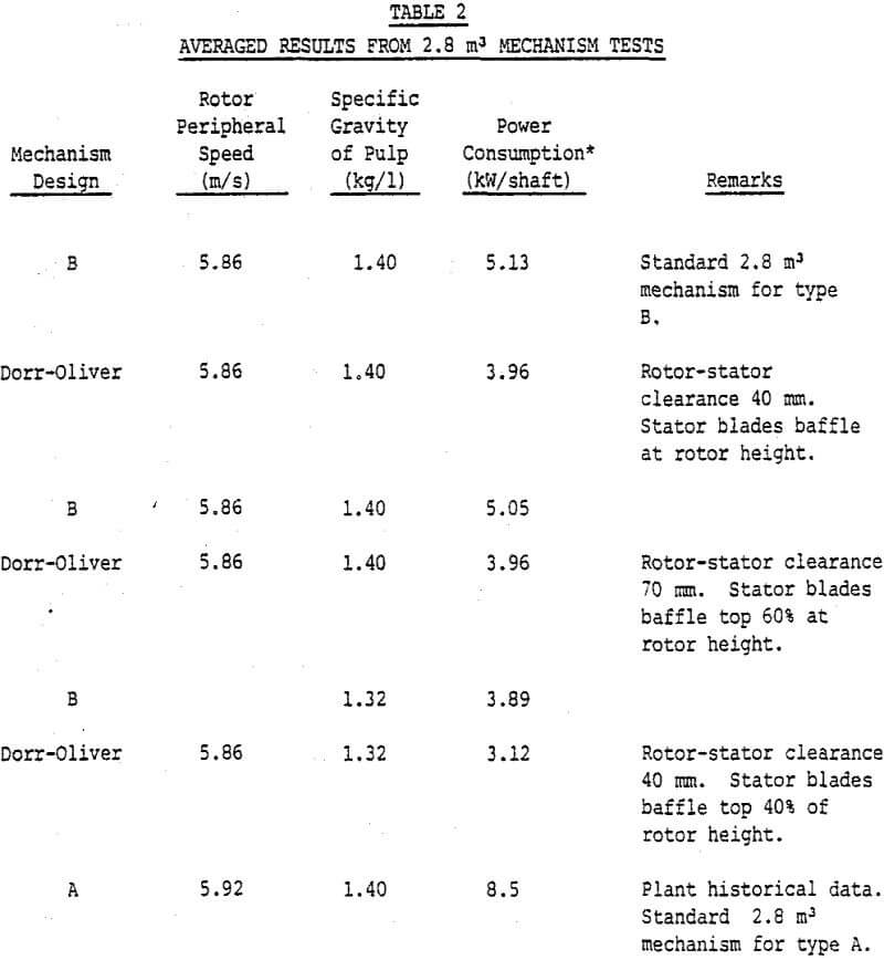
Power draw per shaft was 3.96 kw (5.3 BHP) for the DO-100 units. Power draw for the type B units averaged 29.5 percent higher at 5.1 kw (6.9 BHP) per shaft. In this plant, the type A units typically draw more than 7.46 kW (10 BHP) per shaft, when fitted with new rotors.
Low feed solids during this period resulted in lower power consumptions, for all the mechanisms. From Table 2 average power consumption per shaft for the DO-100 units was 3.1 kW (4.21 BHP). The type B mechanisms drew an average of 3.9 kW (5.2 BHP) per shaft, an increase over the DO-100 prototypes of 24.7 percent.
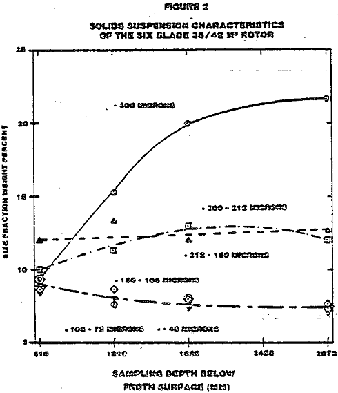
After testing the six-bladed rotor, it was replaced with the four-bladed version. No other changes were made. Soon after start-up, it was evident that it could not disperse sufficient air nor could it adequately suspend the solids. This was in spite of the fact that the cell motor was drawing over 20% more power than for the six-bladed rotor.
