Table of Contents
- Description of Oil Recovery Process
- Displacement Studies in which Complete Miscibility is Maintained at all Times
- Determination of Concentration Profiles in the Mixing Zone
- Displacement of LPG by Natural Gas Under Conditions of Partial Miscibility Core Systems Used
- Characteristics of Miscible Fluid-Mixing Zones
- Effect of Displacement Rate on Miscible Fluid-Mixing Zones
- Application
One-third to one-half of the original oil is left in most reservoirs even after thorough gas driving or waterflooding. In contrast, essentially all of the oil contacted can be recovered by flooding with a solvent (a fluid miscible with the reservoir oil). It is not economical to fill a reservoir with solvent since the value of the solvent would very likely exceed that of the oil. A practical method would be to inject a small bank of solvent to displace the oil. This solvent bank in turn could be driven through the rock by a less valuable scavenging fluid, such as natural gas which is also miscible with the solvent. Such a method of oil recovery was studied in the laboratory using long (up to 95 ft) core systems.
Description of Oil Recovery Process
The solvent oil recovery process will be described in
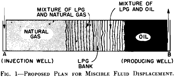
terms of a linear displacement operation which would represent an end-to-end flood in field operations. This type operation is capable of providing maximum areal sweep efficiency and, therefore, maximum oil recovery. Sometime during the displacement, the distribution of the fluids in the reservoir would be as depicted in Fig. 1. If Well A is the injection well, and Well B is the production well, then between these two, five distinct zones will be present. From the producing well into the reservoir will exist a zone of original oil. This is followed by a zone containing mixtures of oil and LPG. In this LPG-oil mixing zone, the concentrations of LPG will increase in the direction of the injection well ultimately grading to pure LPG. The zone of 100 per cent LPG will be followed by another zone consisting of a mixture of LPG and gas which progressively changes in the direction of the injection well to a point where the hydrocarbon pore space is completely filled with natural gas.
Displacement Studies in which Complete Miscibility is Maintained at all Times
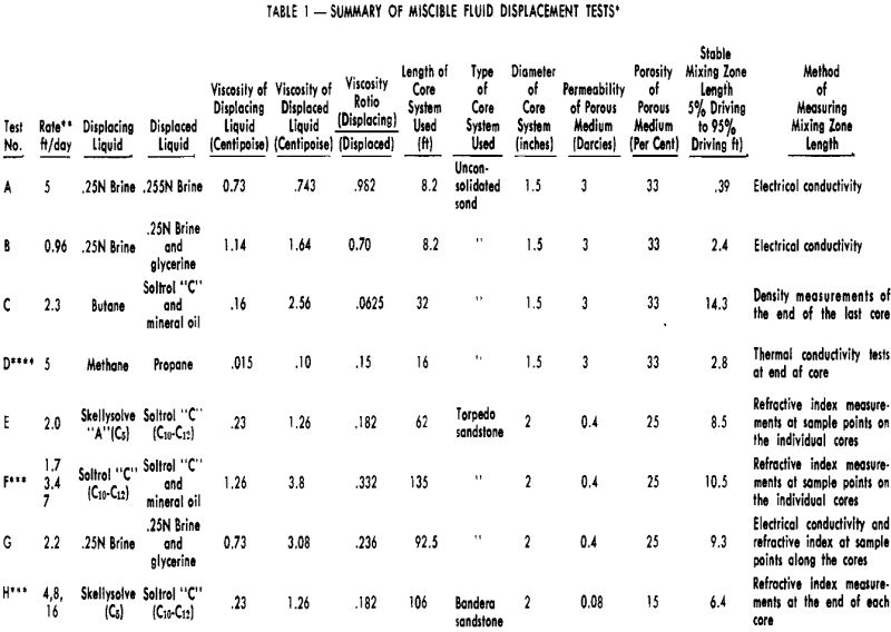
The three types of core systems given below were used in these miscible displacement studies:

The individual cores were all encased in Lucite and were heated under pressure to make the Lucite conform to the contours of the sandstones, thereby confining the flow of fluids to the pore space of the rock. Because of the limited length of a natural sandstone core that could be obtained with coring equipment, it was impossible to obtain natural sandstone cores any longer than 10 ft. Unconsolidated sand cores varied in length from 4 to 16 ft. To simulate displacement in a long core, the individual cores were connected in series with small Cubing connecting the cores to form core systems up to 95 ft in length.
Determination of Concentration Profiles in the Mixing Zone
In the brine-glycerine tests, concentrations were determined by electrical conductivity measurements. The cores used for the brine-glycerine tests were equipped with conductivity taps placed along the cores at 5 cm intervals. Resistances were measured across adjacent electrodes and concentration of the driving phase was determined from a correlation of resistance vs concentration which had been experimentally determined.
In the displacement tests in which hydrocarbons were used, concentrations were determined by means of refractive index, thermal conductivity, or density measurements on withdrawn samples. Selection of the method to be used was based primarily on the volatility of the fluid that was being sampled. Samples were taken from the mixing zone by: (1) sampling at timed intervals from the end of the outlet core or between cores while the mixing zone flowed by the sample point, or (2) withdrawing samples simultaneously from various sampling points in the side of the core.
Displacement of LPG by Natural Gas Under Conditions of Partial Miscibility Core Systems Used
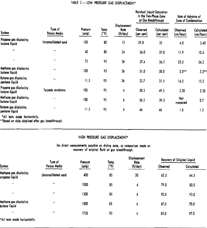
Unconsolidated sand-packed cores and Torpedo sandstone cores were used in these gas drive experiments. Physical properties of the cores were given in the previous section. In the low pressure displacement studies, the cores used were 4 ft in length. An unconsolidated sand-packed core 8 ft long was used in all of the higher pressure gas drives which approached the critical pressure.
The cores to be flooded were saturated with the particular light hydrocarbon liquid by evacuating the core, flowing several pore volumes of gaseous hydrocarbon in at a pressure considerably above its vapor pressure. The producing rate during the test was maintained constant by withdrawing the liquefied hydrocarbon with a constant rate displacement pump. Gas was injected at a constant pressure and measurements were made on the volume of dry gas injected at the operating pressure and temperature. During each test, data were taken on liquid production, length of gas penetration, and the rate of advance of the visible zone.
Characteristics of Miscible Fluid-Mixing Zones
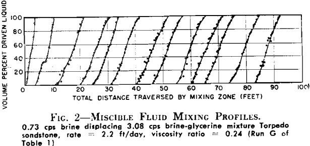
Miscible fluid displacement studies conducted in long core systems indicate that the mixing zone grows rapidly during an early initiating period, but that, as it continues to move through the core system, the rate of growth continually decreases. After sufficient distance is traversed, the mixing zone length appears to stabilize within experimental accuracy. While it is possible that small increases in mixing zone growth were masked by the experimental procedure used, rates of growth of this magnitude are considered to be negligible for practical engineering purposes.
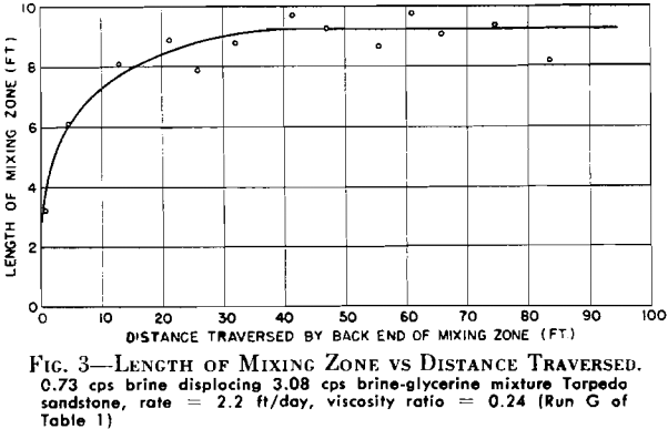
The apparent stabilization of the miscible mixing zones is in disagreement with a theoretical analysis of this type problem. In analyzing the displacement of miscible fluids in terms of a combination of convection and diffusion, relationships are obtained which indicate that the mixing zone length should continually grow,
that it should grow as some function of the square root of the distance traversed, and the amount of growth should vary with velocity. A possible explanation of the apparent stabilization of experimental mixing zones could be that, although diffusion is an important factor within a single pore, diffusional effects appear to be negligible between pores. Because of the extremely short diffusion paths present in individual pores, the rate of diffusion could be fast enough to attain essentially instantaneous equilibrium.
Effect of Displacement Rate on Miscible Fluid-Mixing Zones
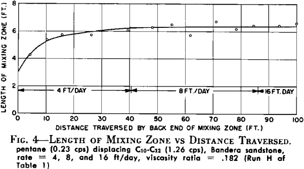
In Tests F and H, changes in rate were made after a stable mixing zone had been established in the core at some initial injection rate. In Test H, the initial rate was 4 ft/day. After the mixing zone had stabilized at this, the rate was increased to 8 ft/day and allowed to move through the core system until another stabilized length could be determined. The final rate used was 16 ft/day. Fig. 4 shows that the mixing zone reached a length of 6.4 ft with the initial injection rate, and the subsequent increases in rate did not cause any measurable increase in mixing zone length. Similar results were obtained in Test F where a fourfold increase in rate caused no apparent change in the length of mixing zone developed at the initiating rate. It appears from these data that the main factors controlling the mixing zone lengths were not diffusional in nature since there was no rate sensitivity observed. This lack of growth with increased rate does not, however, rule out the fact that diffusional effects are an important factor in achieving 100 per cent displacement of the driven liquid. The data support the argument that diffusion is primarily important in individual pores and that diffusion rates, together with short diffusion paths within
an individual pore, can combine to give an appearance of essentially complete convective mixing.
While the data indicate that mixing zone length is independent of displacement rate, it must be realized that this observation cannot be made without qualification. It is possible that at much higher rates, attainment of diffusional equilibrium in individual pores might not be achieved and mixing zone lengths under these conditions would be governed to some degree by displacement rate. This is probably not important from a practical standpoint since rates investigated in Tests F and H exceeded rates that might normally be encountered in field operations.
Application
The procedure for the miscible fluid displacement process basically consists of LPG displacing oil, with the LPG being displaced in turn by natural gas. Because of pressure-volume-temperature relationships, displacement of LPG by natural gas can be accomplished with complete miscibility (at pressures above the critical pressure for the reservoir temperature) or can be of a partially miscible nature below the critical pressure. Individual reservoir conditions, i.e., depth and temperature, and pressure-volume-temperature relationships of the LPG-natural gas system will determine whether complete miscibility can be maintained at all times. For example, using propane to displace oil and natural gas to displace the propane, the critical pressure of the natural gas-propane system would be 1,350 psi at 100°F. At reservoir depths greater than 1,300 ft, miscible fluid displacements using natural gas and propane can be conducted with complete miscibility. For reservoirs shallower than 1,300 ft, displacement of the propane would be partially miscible. This difference in the type of LPG displacement results in the following kinds of miscible fluid displacement operations.
