Table of Contents
The results of this research indicate that diffusion bonding of refractory metal compounds is a promising method for joining dissimilar materials. Fabrication of graded joins by vacuum hot pressing a mixture layer between two end materials proved to be very satisfactory for the joining of nitrides, carbides, and diborides of zirconium and titanium. Joint evaluation showed the joins to be as strong or stronger than the end materials. Also, sound joins of ZrC, ZrN, and ZrB2 were made to alumina and zirconia. Microstructure examinations showed bonding to be promoted by mechanical interlocking of phases and by diffusion of one component into another.
Experience gained in this work indicates that multicomponent refractory metal compound and/or refractory oxide hardware can be fabricated as a monolithic body without the use of low-melting brazes or solders or mechanical fastening devices.
The Bureau of Mines undertook this study to investigate fabrication methods and bonding mechanisms for making graded joins of refractory metal carbides, borides, nitrides, and oxides with each other and refractory metals. This is in anticipation of the need for more refractory electron tube envelopes and for monolithic refractory shapes that would be serviceable in two different environments. Thus, hardware that requires a dual composition-oxidation-resistant materials in one portion and capacity to withstand a reducing environment in another portion-could be easily fabricated.
The work described in this report includes joining studies on ZrC, ZrN, ZrB2, and ZrO2 and an evaluation of the properties of these materials and the graded joints resulting from their union.
Graded-joint fabrication was accomplished by vacuum-hot-pressing together preformed cylinders of the materials separated by a wafer containing a 50-50 weight-percent mixture of the materials being joined. In this method, originally developed by Porembka to bond metals and ceramics, the thermal-expansion gradient is smoothed out at the joint by the graded composition. Zimmer also describes the compositional grading process for joining dissimilar metals which have greatly differing thermal expansions. Diffusion bonding of carbides to refractory metals by hot-pressing butt joints has been investigated by Burykina and Evtushenko. By taking advantage of diffusion bonding effects and compositional grading, we have successfully fabricated satisfactory binary graded joints between ZrC, ZrN, and ZrB2. The works of Porembka and Zimmer include graded joining of dissimilar metals and metals to ceramics. However, our work adds a different class of materials, namely the refractory metal compounds. These studies, together with the work of Burykina and Evtushenko on diffusion welding of refractory carbides to refractory metals, provide important insight into the problems of joining the major classes of high-temperature materials.
Character of Materials and Products
Analyses of Starting Materials
Because the compositions and properties of most of the refractory metal compounds vary greatly from one source to another, the materials used in this work were characterized carefully.
Spectrographic and Gaseous Impurities
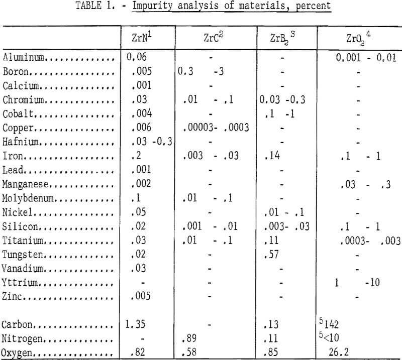
An analysis was made to determine the type and amount of metallic and gaseous impurities on the starting materials. Results of the analysis are shown in table 1.
Compound Identification
An X-ray diffraction examination made on ZrC and ZrB2 showed only ZrC and ZrB2 present. The primary constituent for ZrN was ZrN, with a barely detectable trace of monoclinic ZrO2. The only constituent found for (ZrO2)0.9·(Y2O3 )0.1 was cubic ZrO2 solid solution.
Particle-Size Distribution
It was necessary to reduce the particle size of the commercial powders; consequently, particle-size analyses had to be made before and after milling. Thus, in subsequent grinding operations, the particle-size distribution can be reproduced to insure similarity in all products. The ZrC was milled 6 hours in an iron vibratory mill, and then leached in a 4 N HCl solution to remove the iron contamination. Maximum particle size of the ZrC powder was reduced from 35 microns to 10 microns. A reduction in maximum particle size of the ZrB2 powder from 45 microns to 15 microns was achieved by milling for 4 hours in a tungsten carbide-lined vibratory mill. A comparable reduction in particle size in the ZrN powder, from 25 to 10 microns, resulted from a 2-hour grind in the tungsten carbide mill. Parts A, B, and C of figure 1 show particle-size
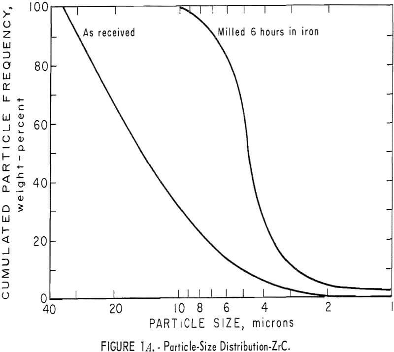
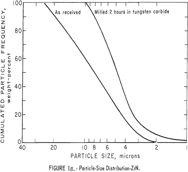
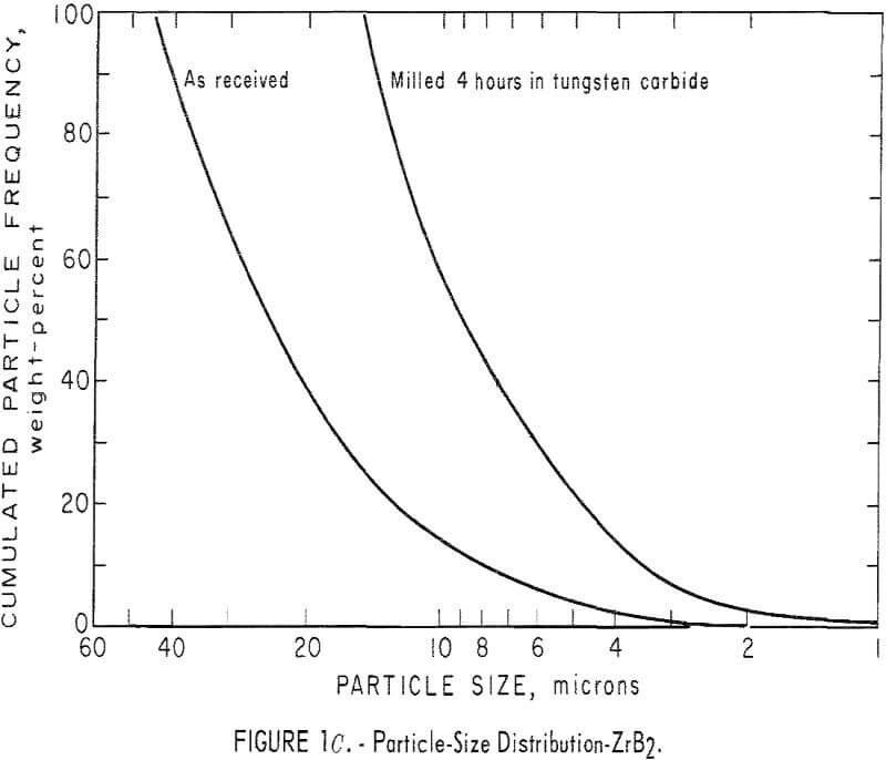
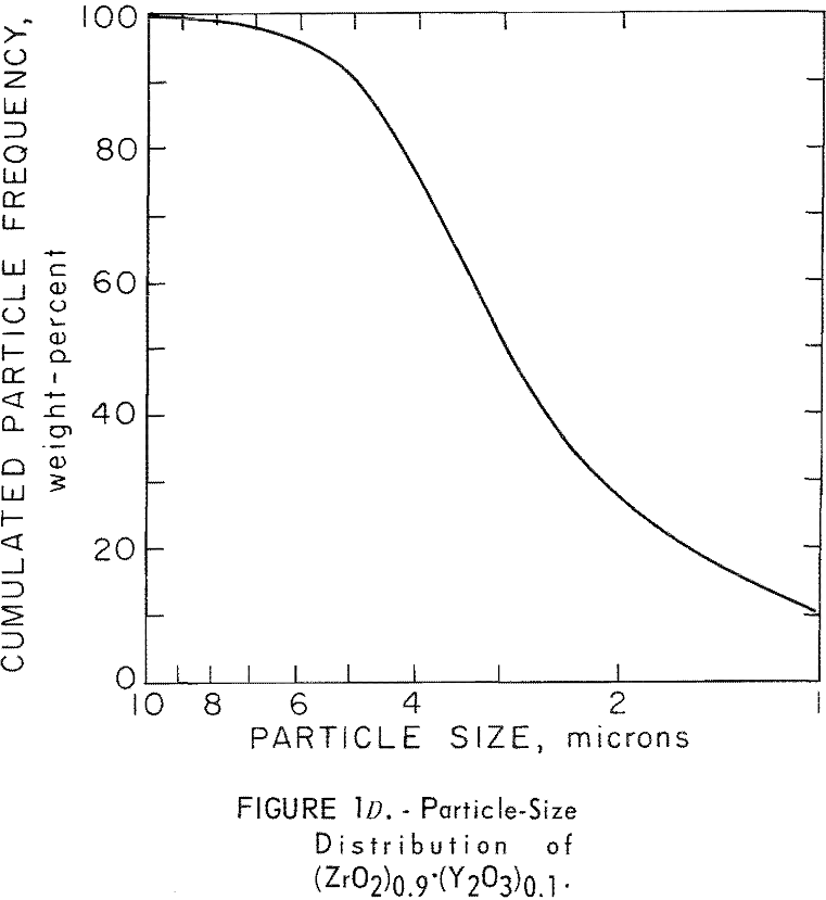
distribution for ZrC, ZrN, and ZrB2 before and after milling. Figure 1D shows particle-size distribution for (ZrO2)0.9·(Y2O3 )0.1. Particle-size distribution was determined by an optical microscope method.
Pycnometric Density
Densities of the as-received ZrC, ZrN, ZrB2, and ZrO2 powders were determined on a Beckman Model 930 air-comparison pycnometer. Helium rather than air was used for ZrC because of the pyrophoric nature of finely divided ZrC. The density values for the powders are as follows, in grams per cubic centimeter: ZrC, 6.46 ±0.02; ZrN, 7.15 ±0.02; ZrB2, 6.09 ±0.02; ZrO2 , 5.77 ±0.02. In this report, all density values expressed in percent of theoretical are relative to these pycnometric densities.
Vacuum-Hot-Pressed Products
Physical and Mechanical Properties
Bulk Density
Bulk-density measurements were made on specimens of ZrC, ZrN, and ZrB2 which had been vacuum-hot-pressed at 2,100° C and 4,000 psi. Each specimen was carefully measured and weighed after sectioning into cubes on a diamond thin-sectioning machine. The bulk-density and percent of theoretical density values are as follows:
ZrC, 6.33 g/cm³ ±0.01 = 97.9 percent of theoretical.
ZrN, 6.57 g/cm³ ±0.01 = 91.9 percent of theoretical.
ZrB2, 6.03 g/cm³ ±0.02 = 99.0 percent of theoretical.
ZrO2, not determined.
Thermal Expansion
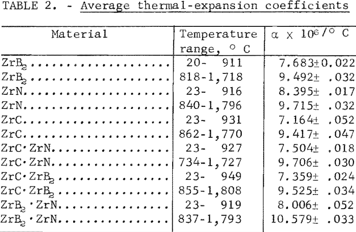
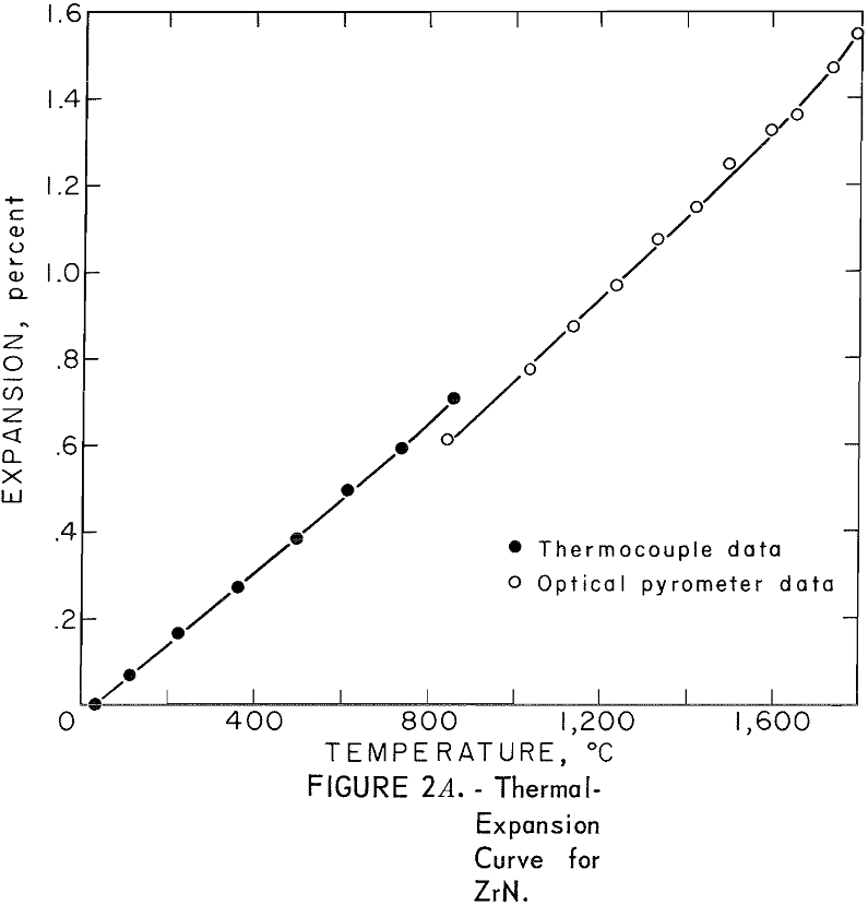
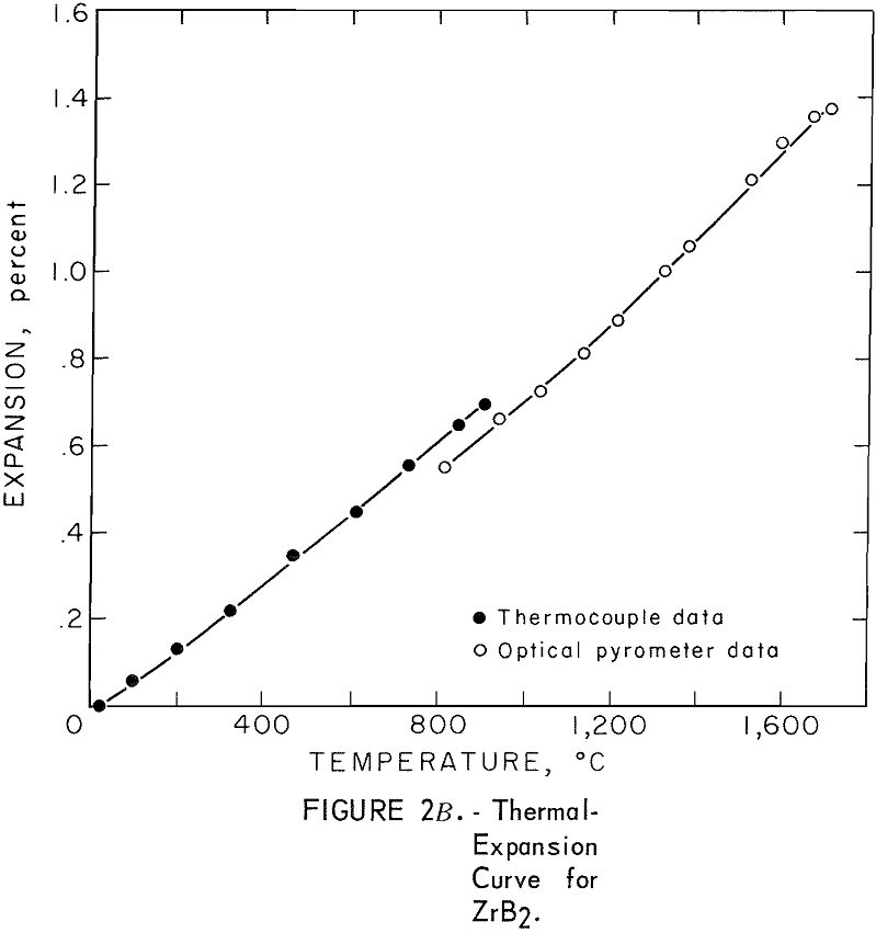
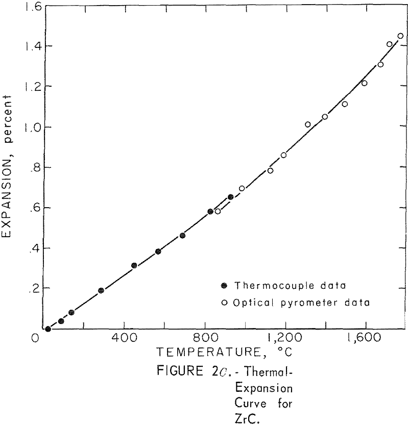
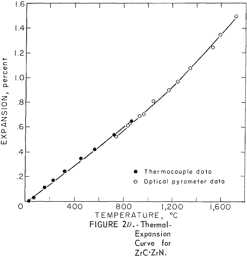
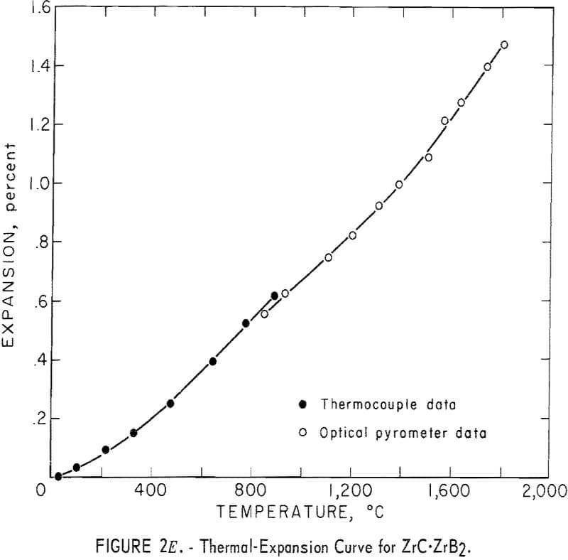
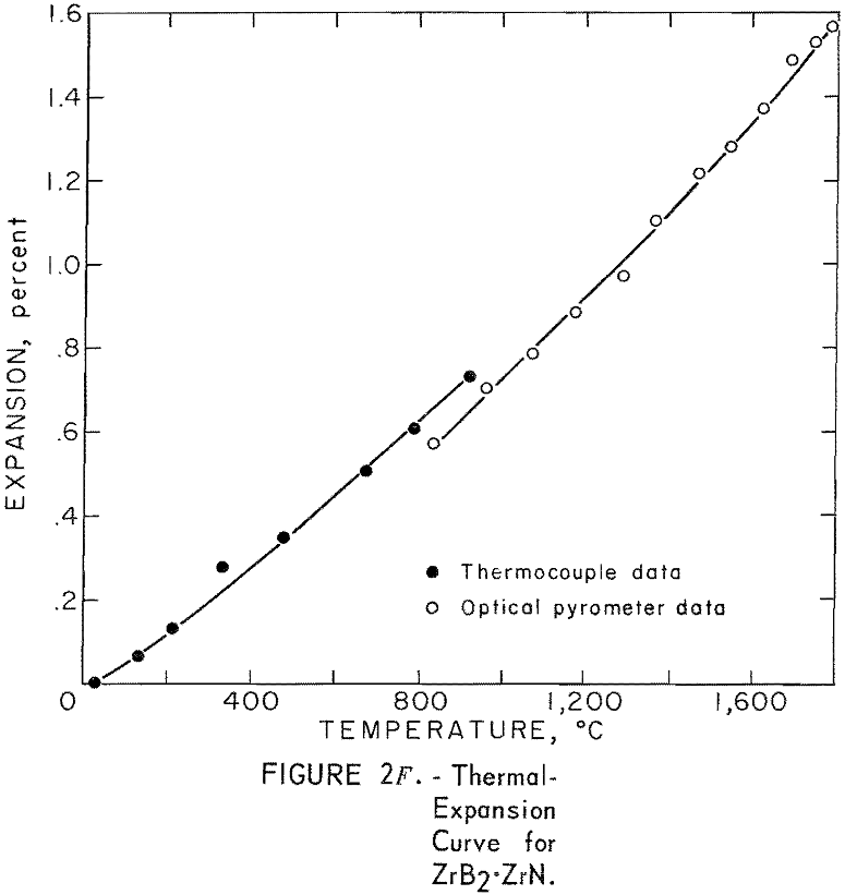
One very important property influencing the success of any joining operation is thermal expansion. Coefficients of thermal expansion were therefore measured for vacuum-hot-pressed ZrC, ZrN, ZrB2, ZrC·ZrN, ZrC·ZrB2, and ZrB2·ZrN. No measurements were made on ZrO2 because of specimen fabrication difficulties. The thermal-expansion measurements were made by observing the relative displacement of the specimen ends as they were heated in a graphite resistance tube furnace. Observation and measurements of thermal expansion were made with two tandem-mounted telescopes fitted with filar micrometer eye-pieces. This assembly can detect displacements as small as ±0.00002 inch at a focal distance of 22 inches; however, experimental reproducibility was within ±0.0005 inch on a 3-inch specimen. The furnace is very similar to the apparatus described by Miccioli and Shaffer. The thermal-expansion tests were done in two steps to eliminate the possibility of a reaction between the thermocouple and the specimen. First, from room temperature to about 800° C, the temperature was sensed with a Pt versus Pt-10 Rh thermocouple; above 800° C, an optical pyrometer was used. Expansion versus temperature curves are shown in figure 2. Data from these curves were analyzed by stepwise regression analysis for best fit; the results yielded the coefficients of thermal expansion shown in table 2. The exact reason for the discontinuity of thermal-expansion curves is not known, but it may be due to error in establishing the zero point in the optical pyrometer portion of the curve. This is caused by a slight sintering of the specimen during the initial part of the runs.
Thermal-Shock Resistance
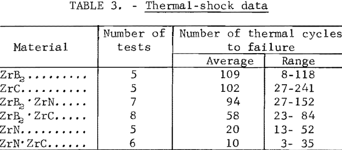
Thermal-shock tests were made on disk-shaped specimens of vacuum-hot-pressed ZrC, ZrB2, ZrN, ZrC·ZrN, ZrB2·ZrN, and ZrC·ZrB2. The specimens, ½ inch in diameter and 1/16 inch thick, were sawed from hot-pressed cylinders using a diamond thin-sectioning machine. Each disk was alternately heated and cooled in a radiofrequency furnace until visible cracks occurred. Each of these thermal cycles consisted of a 20-second heating to 1,400° C and a 20-second cooling to 600° C. For determinations of relative thermal shock resistance, the number of thermal cycles to failure was recorded. Although the results were not considered quantitative, a definite pattern of thermal-shock resistance was determined. ZrB2 was the most resistant to shock, followed in order of decreasing resistance by ZrC, ZrB2·ZrN, ZrB2·ZrC, ZrN, and ZrN·ZrC. Table 3 shows the average number of thermal cycles to failure for each material.
Strength
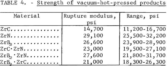
Modulus of rupture measurements were made on vacuum-hot-pressed cylinders of ZrC, ZrB2, ZrN, ZrN·ZrC, ZrB2·ZrN, and ZrB2·ZrC to provide a comparison of transverse strength of the materials, A “single-point” loading jig with 0.25-inch- diameter bearings and a 1.25-inch span was used on a universal testing machine that loaded at a strain rate of 0.025 inch per minute. Five specimens, ½ inch in diameter and 1-5/8 inches long, were tested for each composition. The strength values, expressed as rupture moduli, are shown in table 4.
Chemical Properties
Melting Point
The congruent melting temperatures of ZrC, ZrN, and ZrB2 were measured, and the liquidus temperatures were determined for the binary mixtures containing 50 weight-percent of each compound. A self-resistance furnace, which is described by Adams and Beall, was used for heating the specimens; the temperature was measured with an optical pyrometer. Melting was noted when an 0.050-inch-diameter black-body hole in the specimens changed brightness as observed through the optical pyrometer. Melting point values were as follows: ZrC, 3,380° C ±50°; ZrB2, 3,220° C ±50°; and ZrN, 2,980° C ±50°. For comparison, Cronin found the melting point of ZrC to be 3,532° C and 2,982° C for ZrN. Kieffer and Kolbl reported the melting point of ZrC to be 3,250° C. Schwartzkopf and Kieffer claim 3,040° C ±50° as the melting point of ZrB2. Liquidus temperatures for the binary mixtures were determined by noting the optical pyrometer readings at the first sign of liquid formation in the specimen black-body holes. Those values were as follows: ZrC·ZrB2, 2,980° C +50°; ZrC·ZrN, 3,410° C ±50°; ZrB2·ZrN, 2,660° C ±50°.
Oxidation Behavior
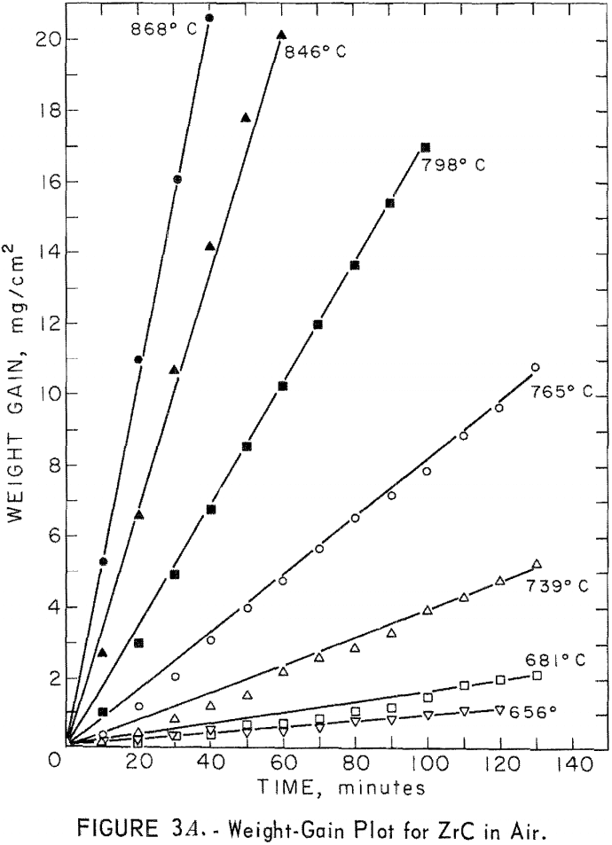
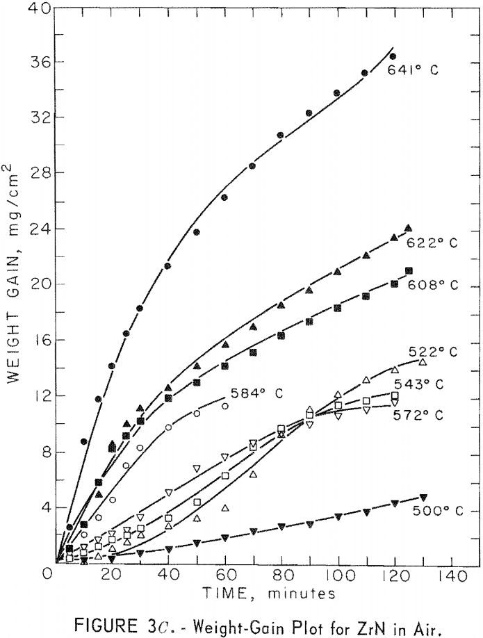
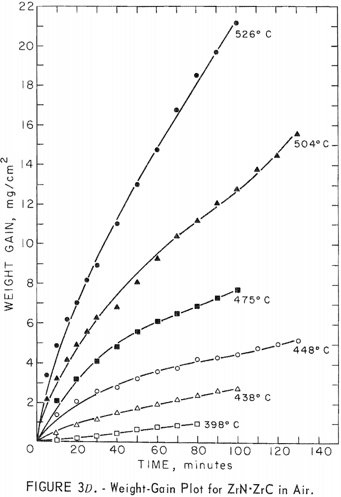
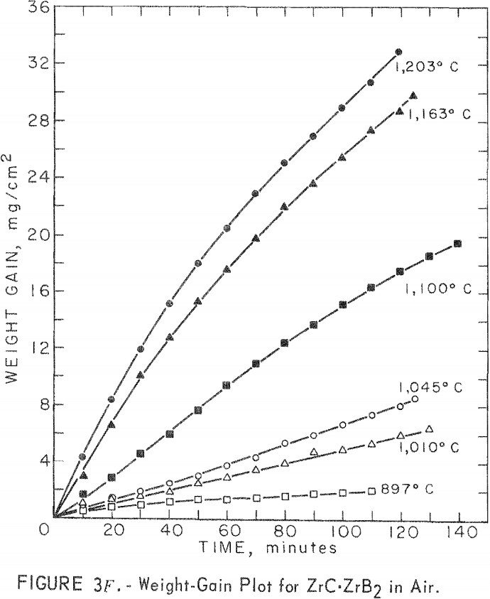
A study of the oxidation behavior of vacuum-hot-pressed ZrC, ZrB2, ZrN, ZrC·ZrB2, ZrC·ZrN, and ZrB2·ZrN in air was made to provide additional information on the limitation of the joins formed between these materials. Isothermal weight-gain measurements were taken on cubical specimens 2 mm on a side. The specimen weight was continuously monitored through a heating cycle in air by recording the output signal from a Cahn electrobalance on a strip-chart recorder. The weight-gain-versus-time curves at constant temperature were then constructed by stepwise regression analysis of the weight-gain data. Detailed analysis of the weight-gain curves was made for ZrC and ZrB2 to yield oxidation rate constants and activation energies. Such a detailed study was not continued for ZrN and the binary mixture compositions because the weight-gain curves were complex, apparently a result of several interacting mechanisms. The oxidation rate constants and activation energies, therefore, were not computed because the rate-controlling mechanisms were not determined.
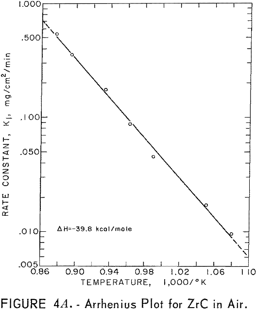
Best fit curves representing data from the stepwise regression analysis of weight-gain-versus-time tests are shown in figure 3. Activation energy curves for oxidation of ZrC and ZrB2 are shown in figure 4.
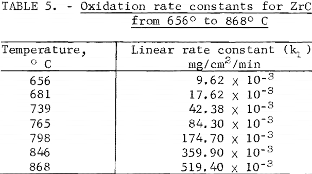
A linear-oxidation rate was found for vacuum-hot-pressed ZrC in air with an activation energy of 39.8 kcal/mole. The data for ZrC between 656° and 868° C can be expressed in an Arrhenius- type equation which describes the temperature dependence of oxidation rate as
ln k1 = 16.858 – 20.03/T
where k1 is the linear rate constant and T is absolute temperature. Table 5 shows the ZrC linear-rate constants for each isothermal test. One test at slightly above 868° C was discarded because of catastrophic oxidation of the specimen. These ZrC specimens were 95.2 percent of theoretical density.
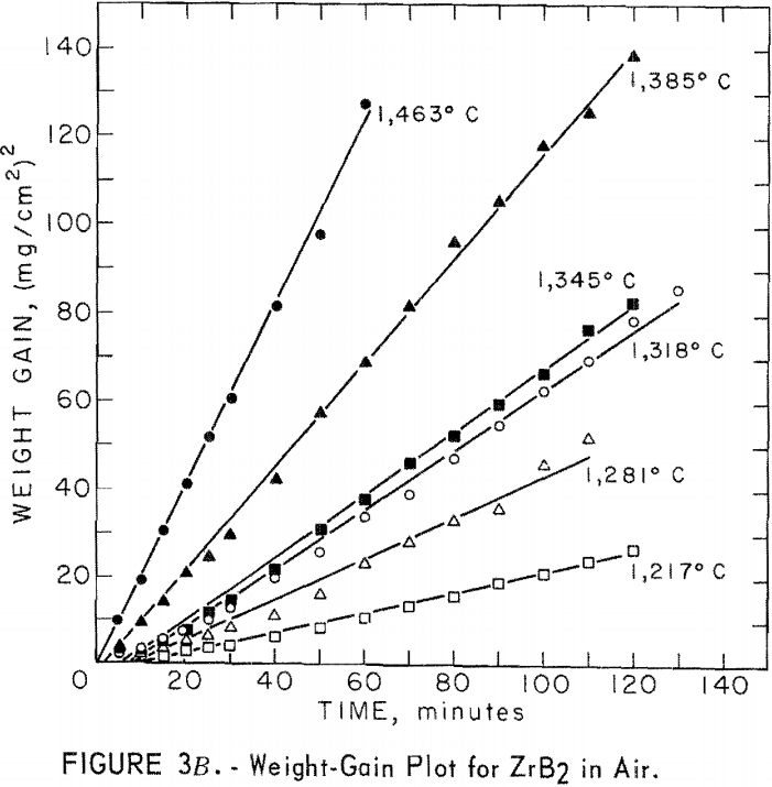

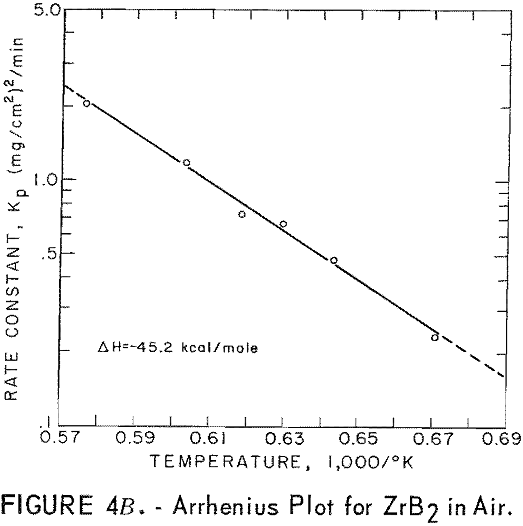
A parabolic oxidation rate was found for vacuum-hot-pressed ZrB2 in air, and the activation energy was determined to be 45.2 kcal/mole. The Arrhenius equation describing the temperature dependence of oxidation rate for ZrB2 is
ln kp = 13.867 – 22.78/T
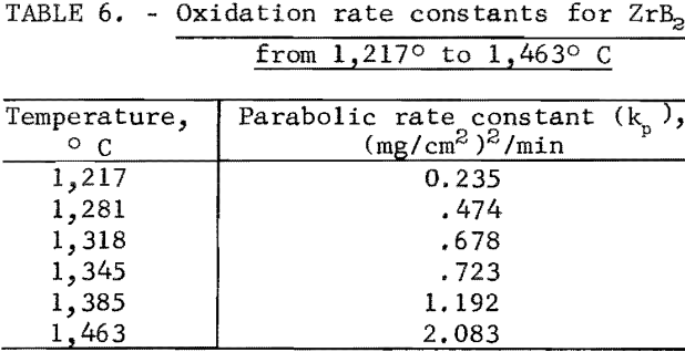
where kp is the parabolic rate constant and T is absolute temperature. Parabolic rate constants for the 1,217° to 1,463° C temperature range are shown in table 6. Catastrophic oxidation occurred in ZrB2 at slightly above 1,463° C. The ZrB2 specimens had a density of 95.6 percent of theoretical.
Compatibility of Materials
Prior to the joining tests, a series of compatibility runs were made to determine whether any undesirable reactions would occur between the components of the join assemblies. Two series of tests were made: The first by pressureless sintering and the second by vacuum hot pressing.
Cold-Pressed and Vacuum-Sintered Bodies
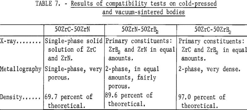
Cylindrical bodies containing equal parts of ZrC + ZrB2, ZrC + ZrN, and ZrB2 + ZrN were cold-pressed in a ½- inch diameter steel die and ram-set at 20,000 psi. The powders were well mixed in a vibratory mill, then dampened with benzene prior to cold pressing. The benzene acted as a binder and was easily removed by heating just before vacuum sintering. Following the cold pressing, the bodies were vacuum-sintered in an induction furnace at 2,000° C for 80 minutes. Specimens for X-ray diffraction and metallographic examination were removed from each body by sectioning on a diamond thin-sectioning machine. The extent of compatibility of the mixtures was determined from the results of the X- ray diffraction and metallographic examinations. These results are shown in table 7 and indicate that no adverse reactions would occur at the test conditions. These results also indicated that higher densities were desirable in the ZrB2·ZrN and ZrC·ZrN systems. Therefore, a series of bodies for compatibility tests were fabricated by vacuum hot pressing.
Vacuum-Hot-Pressed Bodies
Cold-pressed cylindrical bodies, as previously described for pressureless sintering tests, were vacuum-hot-pressed in a ½- inch- diameter graphite die and ram. The die and charge were heated in an induction furnace hot press in a 10 -5 torr vacuum. These bodies were heated to 2,100° C, held at 2,100° C for 30 minutes, and then cooled to room temperature in 2 hours. A pressure of 4,000 psi was applied to the bodies during heating, but was released during cooling. Following the fabrication, the vacuum-hot-pressed bodies were sectioned for X-ray diffraction and metallographic examinations, and density measurements. The results of these examinations showed no adverse reactions that would preclude the use of the compound mixtures in join assemblies.
X- Ray Diffraction and Metallographic Examinations
Fifty Percent ZrC + Fifty Percent ZrN
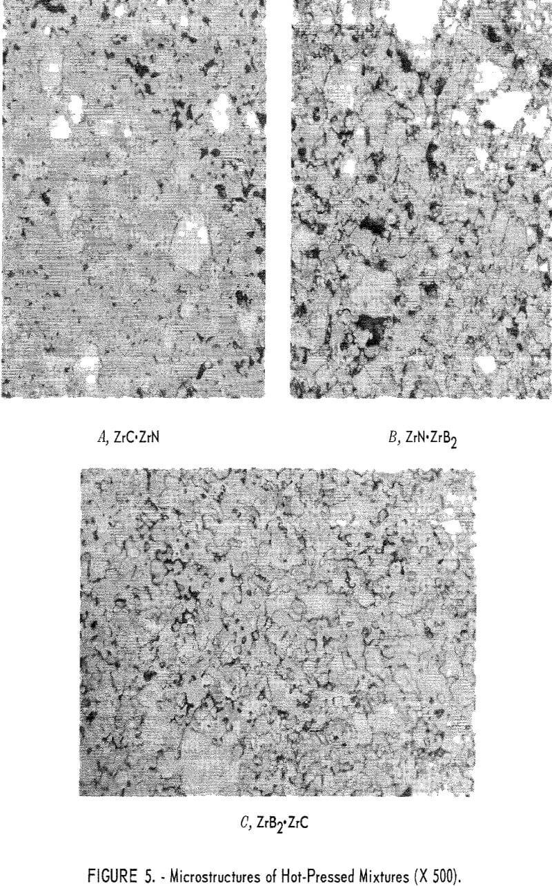
Two phases were noted by X-ray diffraction. The primary constituent was a ZrC-ZrN solid solution, and a minor constituent was ZrC. The ZrC – ZrN phase was a striking maroon color. Two other phases were seen and were identified as ZrC and ZrN, Figure 5 shows microstructures of the hot-pressed mixtures; panel A of figure 5 shows the ZrC·ZrN phase, in which the rounded light-gray grains are ZrC, and the white grains are ZrN.
Fifty Percent ZrN + Fifty Percent ZrB2
Two phases were reported as the primary constituents, ZrN and ZrB2 in equal amounts. Panel B in figure 5 shows the ZrB2 phase as light-gray grains. Most of the ZrB2 grains are longer in one direction than another. The white phase in this photograph indicates the ZrN grains. Some very small dark grains were identified as ZrO2.
Fifty Percent ZrC + Fifty Percent ZrB2
Equal amounts of ZrC and ZrB2 were reported as the primary constituents. The ZrC appears as a light-gray phase and the ZrB2 as a darker gray phase in panel C of figure 5. This mixture hot-pressed to a very dense structure. It appears that sintering of the ZrC was enhanced by the presence of ZrB2.
Fabrication of Graded Joints
The fabrication procedure for making graded joints consisted of two steps. The first was the prefabrication of the individual joint components; namely, one cylindrical body of each of the two compounds being joined, and a disk-shaped wafer consisting of a mixture of equal parts of those two compounds. The second was vacuum hot pressing the two cylindrical bodies with the mixture wafer between them in a three-component assembly,
Prefabrication of Joint Components
Powders for the end components of each join were dampened with benzene just prior to cold pressing into ½-inch diameter cylinders. The mixture wafers, 1/8 inch thick, were also cold-pressed following a thorough mixing of the powders in a vibratory mill. Benzene was added as a binder to give the bodies green strength after cold pressing. All of the components were cold-pressed in a steel die and ram-set at 20,000-psi pressure.
Vacuum-Hot-Pressing Joint Components
The three-component assembly was joined by vacuum hot pressing in a graphite die and ram. Each component was loaded, one on top of the other, into the ½-inch-diameter die, and the whole unit was inserted into the hot-press furnace. A cutaway graphite die containing the three components is
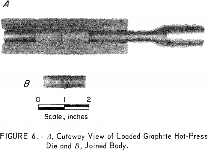
shown in figure 6, Each joined body was hot-pressed in vacuum at 4,000 psi for 30 minutes at 2,100° C. Heating and cooling rates were approximately 20° C/min. The finished body length was 1-½ inches.
Joint Evaluation
A series of joined bodies in the ZrC, ZrB2, and ZrN systems were fabricated for strength tests, thermal shock tests, and metallographic examination.
Strength
Qualitative strength tests were made on joined bodies in each of the three systems studied. The modulus of rupture testing method described earlier was used; however, because of the inhomogeneous nature of the three component bodies, the stress distributions were complex and led to widely scattered strength values. Nevertheless, these tests were useful in demonstrating that the joins were sound. Most of the failures were in the parent materials, rather than at the join interfaces.
Thermal Shock
A series of qualitative thermal-shock tests were made on joined bodies of each of the three systems containing ZrC, ZrB2, and ZrN. These tests were performed to show which portion or component of the join assembly was the most susceptible to thermal-shock damage.
Method
Each specimen was heated very rapidly to 1,500° C in the self-resistance “melting-point” furnace described earlier. The power was shut off and the specimen allowed to cool rapidly. The rapid heating and cooling cycles were repeated until the specimen fractured; the damaged portion was noted.
Results
In the ZrB2-ZrC system, the carbide end fractured first. Neither the boride nor the graded zone failed. The nitride portion of the ZrB2-ZrN system was the first to fail, and again, the boride and the graded zone survived. Zirconium carbide was the first to fail in the ZrC-ZrN system; none of the other portions failed.
Microstructure Examination
Metallography specimens of the graded join bodies were prepared by making longitudinal slices through the specimens on a diamond thin-sectioning machine, thus exposing the cross section through the join. The specimens were then mounted in Bakelite and polished by normal techniques. A microstructure study was then made.
ZrC to ZrN System
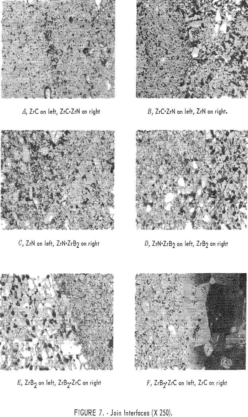
The join interface between ZrC and the ZrC·ZrN mixture layer is shown in figure 7, panel A. This join is well bonded, as indicated by the wide diffusion zone produced by solution of ZrC in the ZrC·ZrN phase. It appears that a very smooth compositional gradient exists at the join. ZrC is the light-gray phase at the left of the photograph, and the darker gray phase to the right is ZrC·ZrN solid solution. The large white angular grains are undissolved ZrN.
Figure 7, panel B shows the ZrC·ZrN to ZrN join interface. The gray matrix on the left is the ZrC·ZrN solid solution, and the white material is ZrN. Some porosity has been formed at the interface, possibly from partial decomposition of ZrN. The extent of diffusion appears to be small across the interface.
ZrN to ZrB2 System
Figure 7, panel C shows the ZrN to ZrN·ZrB2 join interface. Diffusion across the interface appears to be fairly extensive.
The two-phase region to the left in figure 7, panel D, is the ZrN·ZrB2 portion, and the white grains on the right are ZrB2. A dark-gray material in the ZrB2 area was identified as ZrO2. Black, round areas are voids. In ZrB2 the voids have assumed a spherical shape, and are all nearly the same size. There appears to be good diffusion across the interface.
ZrC to ZrB2 System
The join interface between ZrB2 and ZrB2·ZrC is shown in figure 7, panel E. The light-colored grains appearing on the left side of the field are ZrB2, and the mixture layer is on the right. In the ZrB2·ZrC portion, the light-colored phase is ZrC, and ZrB2 is the gray matrix. The extent of diffusion across this interface appears to be small.
Figure 7, panel F shows the ZrB2·ZrC to ZrC join interface. The ZrB2·ZrC area is on the left of the figure, and the very large grains on the right are ZrC. Visual inspection shows a small amount of diffusion across this interface. The original grain size of the ZrC was less than 10 microns, but it can be seen in the figure that a tenfold increase in grain size has occurred. The grain-size distribution can be seen in figure 8. The fine-grained material at the upper left corner of this photograph is ZrB2·ZrC. Grain size decreases from about 100 microns at the join interface to the original 10 microns about 500 microns away from the interface. There are very few voids in the ZrC
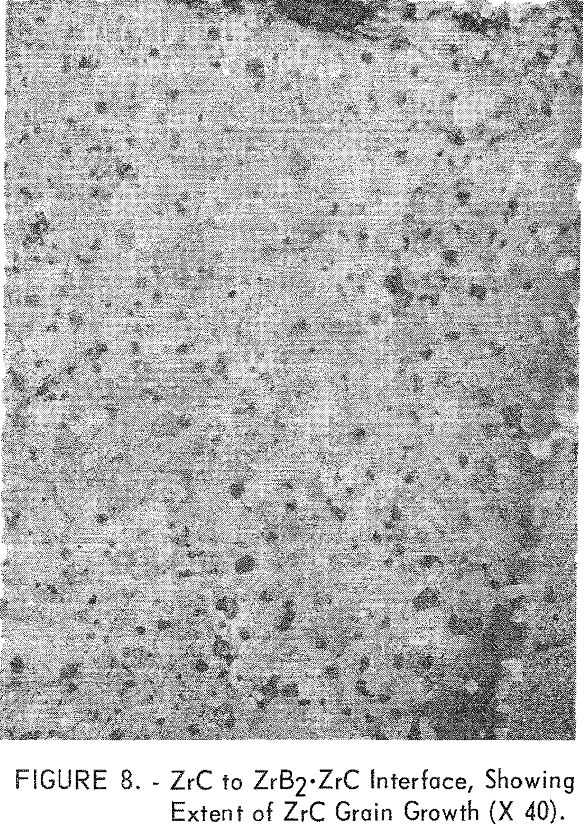
phase near the join interface. It is possible that the grain growth was accelerated by small amounts of boron which diffused across the join into the ZrC. This hypothesis is supported by the fact that the structure of the ZrC in the ZrC·ZrB2, composition was nearly void-free, as noted in figure 5C.
Other Systems
Several series of joining tests were made to demonstrate that the hot-press joining method would be useful in systems other than zirconium and in systems containing an oxide as one component of the joined couple. Successful joins were obtained in systems of TiC, TiN, and TiB2, and in systems of Al2O3 with ZrC, ZrN, and ZrB2. All of these join specimens were sectioned, visually examined, and evaluated.
Titanium Compounds
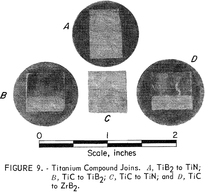
One each of the following joins were made: TiC to TiN, TiN to TiB2, TiC to TiB2, and TiC to ZrB2. These joins were made by hot pressing the component parts, including a 50-50 mixture wafer between the two end portions, at 2,100° C and 4,000 psi for 1 hour in a graphite, die and ram. An argon atmosphere was used. Bonding in each case was excellent; however, the titanium compounds were more prone to cracking than the zirconium compounds, as can be seen in figure 9. It is interesting that no grain growth was noted at the TiC interface with either TiB2 or ZrB2, as was seen in the ZrC-ZrB2 system.
Joins to Oxides
The type of join which mates an electrical conductor to an electrical insulator is of special interest from an electronic application standpoint. The hot-press fabrication method was used successfully to join ZrC, ZrB2, and ZrN (all electrical conductors) to Al2O3 and ZrO2.
Alumina
Bodies of alumina were hot-press-joined to ZrN, ZrC, and ZrB2 with a 50-50 mixture layer between ends. Each joined body was hot-pressed at 1,750° C and 3,000 psi in a graphite die for 1 hour. An argon atmosphere
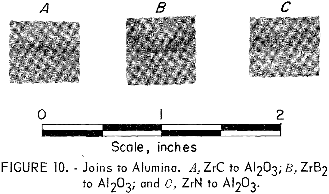
was used. Very strong bonding of the components resulted, and visual examination of sectioned samples showed no evidence of adverse reactions between the compounds. The alumina joins are shown in figure 10, where the alumina end of the assemblies is toward the top of the picture.
Zirconia
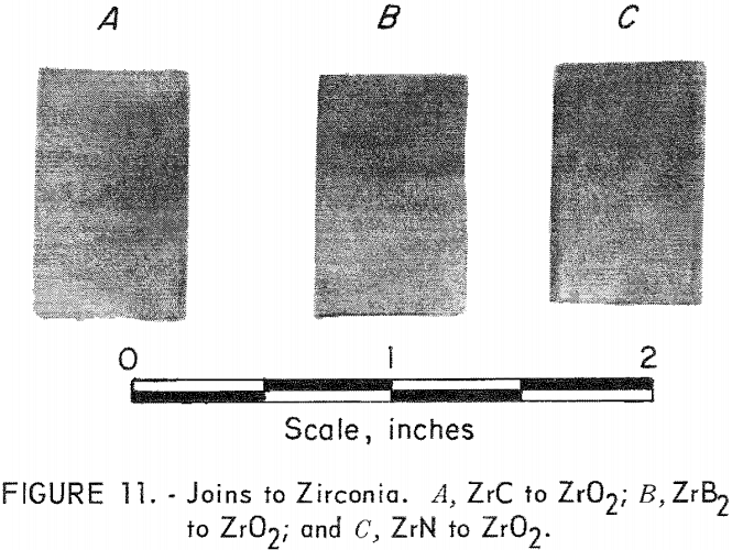
Hot press joining of ZrC, ZrN, and ZrB2 to ZrO2 (yttria-stabilized) was accomplished, but with much more difficulty than in any of the other systems. The major problem was thermal-shock damage to the ZrO2 component of the joins. Sandwich-type joins were made which contained one, three, and five intermediate mixture layers between the ends. Extreme cracking destroyed all specimens containing one- and three-mixture layers, but most of the specimens containing five layers survived. These join bodies were hot-pressed in graphite at 1,800° C for 1 hour in argon. Figure 11 shows a specimen of ZrC joined to ZrO2, ZrB2 to ZrO2, and ZrN to ZrO2. The ZrO2 sections are toward the top of the picture. Composition of the intermediate layers had the proportions 85-15, 75-25, 50-50, 25-75, and 15-85.
Related: 12 Best Metal Glues
