Table of Contents
The Iron Ore Industry has perhaps seen more varied and drastic changes in its approach to crushing and grinding in the last 5 years than any of the other mineral industries. Multimillion ton per year plants have become common place. Centralized control and computers have become an established benefit. Autogenous grinding along with a variety of rod and ball grinding flowsheets are in use.
Primary Crushing
The most common control in a primary crusher installation begins with sensing of the bin level below the crusher discharge. This is usually done using a gamma ray source and detector. High level sensors trigger the “no-dump” lights and protect the crusher from damage due to an overloaded bin. Low level sensors not only actuate the dumping lights, but can be used to control the discharge feeder to protect it from direct blows of large ore chunks.
Hydraulic mantle positioning devices with remote positions indicators are included on most modern primary gyratory crusher installations.
These control devices have served to protect equipment and maintain operating availability. In most cases the crusher operator’s job has not been eliminated because of the necessity of operating the rock hook or lowering the mantle when large chunks bridge the crusher cavity.
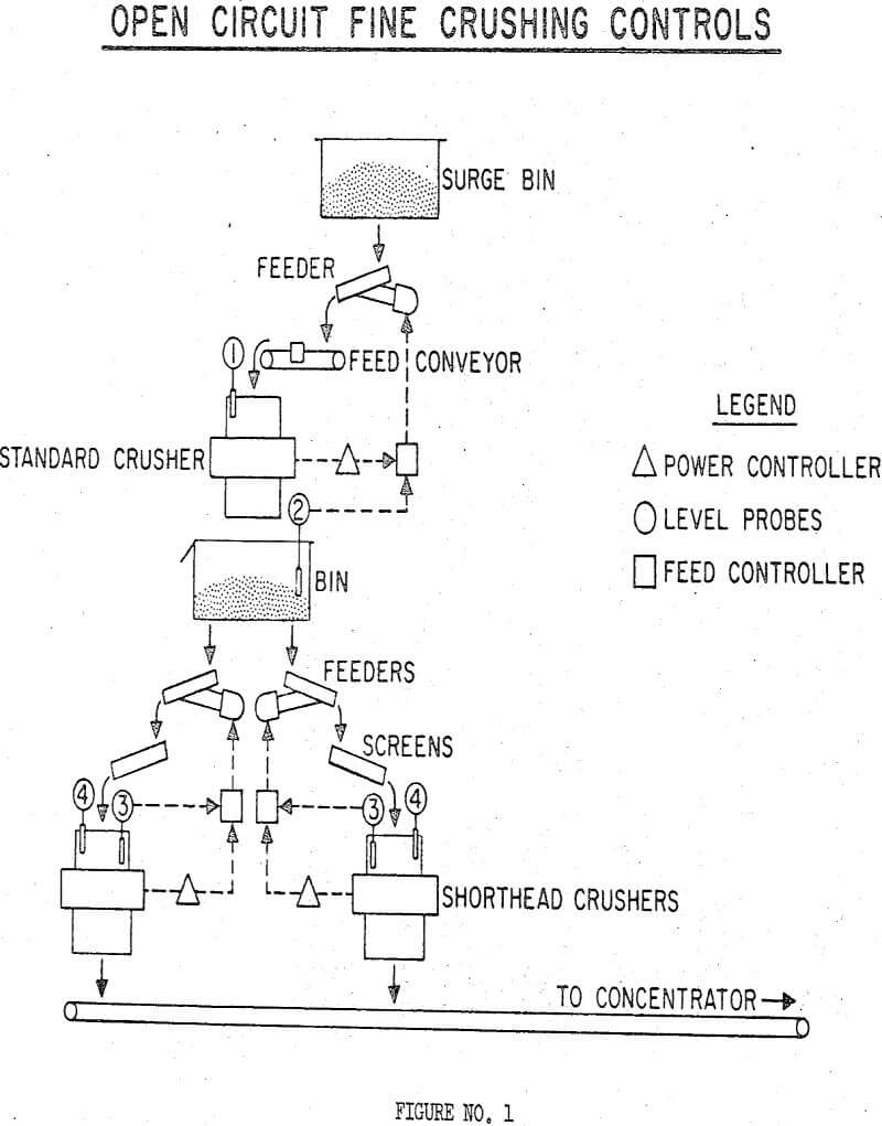
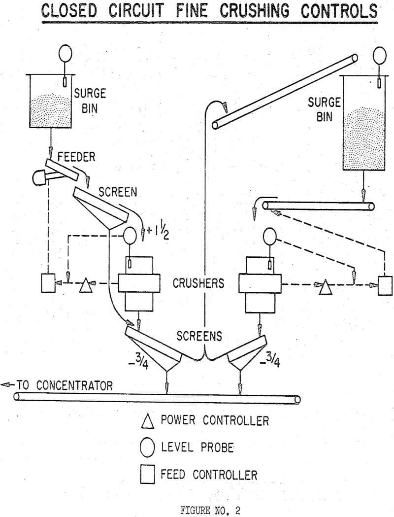
Fine crushing, whether applied to 3 or 4-stage circuits, can be classified as either open circuit or closed circuited with screens.
Rod Mill – Ball Mill
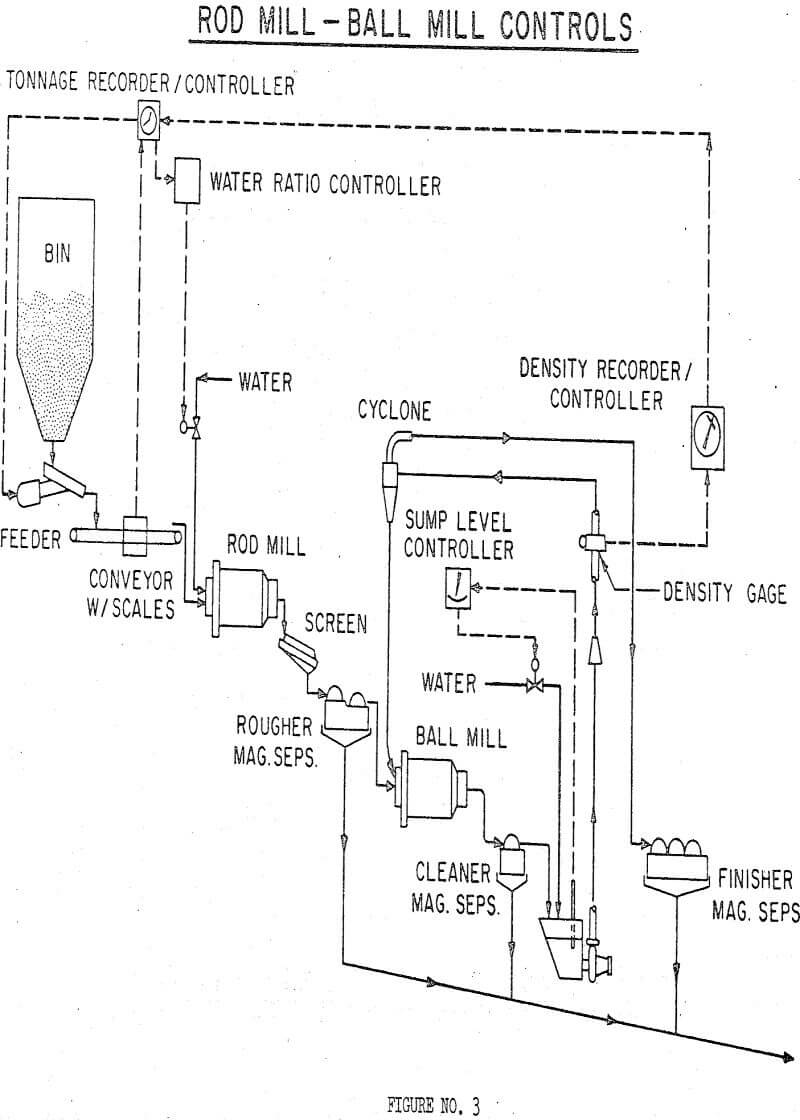
Most of the rod mill – ball mill circuit controls in the Iron Ore Industry are patterned after a scheme developed by Erie Mining Company. This control is based upon the premise that constant volume, and structure of feed to the cyclone will result in a controlled sizing of the cyclone overflow by varying the density of the cyclone feed.
Prior to the introduction of automatic density control on cyclone feed, a manual method on cyclone overflow was used. This consisted of manual adjustment of dilution water to the cyclone feed sump and manual adjustment of the tonnage set point on the automatic feed controller. The cyclone feed pressure was varied to maintain the feed sump at a constant level. This was accomplished automatically through the use of a sump level sensor controlling a vari-speed cyclone feed pump.
Grinding control circuitry is still based upon cyclone feed density controlling rod mill feed tonnage. This scheme permits the selective grinding of the low grade coarse fraction. This results in the advantage of obtaining either a coarser overall grind with the same grade and an increase in throughput, or a better grade at the same grind and throughput.
Controls for a plant having two rod mills followed by three ball mills, have also been developed. The principle of grind control is based upon the cyclone feed density controlling the magnetic tons of feed to the rod mill. Magnetic tons were chosen because of a wide variation in magnetic iron of the feed.
Wet Autogenous – Ball Mill
A problem area in any two stage flowsheet is the utilization of the maximum power capability in each grinding stage. This is particularly true of autogenous grinding, where mill power draw is a direct function of the charge level within the mill.
Controls for a plant with wet autogenous – ball mill grinding incorporate the use of a nuclear density gauge on the ball mill cyclone feed line. The density set point controls the tonnage feed rate to the autogenous mill. An optional control by autogenous mill power is also provided,
In a successful attempt to gain a finer grind in the primary autogenous mill, a 100 ton charge of 1-½” diameter steel balls was added to the primary mills by one operator. The use of these small balls made up for a lack of grinding media and doubled the mill power draw. This balancing of power and grind allowed the plant to reach design tonnage.


