Table of Contents
Adherent, coherent electro-deposits of iridium 15 mils thick and alloys of iridium 4 mils thick were formed in argon atmosphere from fused cyanide electrolytes.
The use of pure iridium to prevent oxidation appears limited to temperatures under 1,000° C because of volatility of the oxide of iridium.
Iridium alloyed with platinum-group metals such as platinum, palladium, or rhodium which have less volatile oxides can be electrodeposited from cyanides and may offer protection to substrates at high temperatures. The hardness of the electrodeposits can also be modified by alloy formation.
Deposits made from aqueous electrolytes either had very low rates of deposition or in the case of the Conn electrolyte were highly stressed and cracked when heavy deposits were made.
Iridium has a melting point of 2,442° C, unusually high resistance to corrosion, and low permeability to oxygen. The metal is very hard and has unusual resistance to a variety of high-melting-point salts; for example, barium titanate, rutile, and the tungstates of calcium, strontium, and barium. Iridium crucibles are widely used in preparing single crystals of these materials for specialized electronic and optical devices. In addition, some alloys of iridium with other platinum-group materials have desirable characteristics; for example, iridium-rhodium alloys have slightly better oxidation resistance than pure iridium and iridium is used as a hardening agent with platinum and palladium and may be used as a diffusion barrier between the refractory metals and a more oxidation-resistant coating.
The Bureau of Mines experimental work was directed toward determining whether thick, adherent, and coherent deposits of iridium could be formed on refractory metal substrates to protect them from oxidation and erosion, and toward clarifying data in the literature involving aqueous electrolytes, with respect to maximum possible thickness of deposits, plating rates, adhesion, and cohesion. Although it was reported that an oxide of iridium volatilizes rapidly at 1,000° C it was felt that some ablation or recession of coating may be acceptable in certain applications. The Bureau also attempted to determine characteristics of the deposits and electrolytes that had not been previously established, and to investigate the formation of iridium alloys. Future reports will include work on electrodeposition of iridium from potassium cyanide, and from a eutectic mixture of sodium cyanide and potassium cyanide in impervious mullite crucibles. Work describing deposition at various temperatures and degrees of bath agitation will be included.
Various methods for depositing iridium have been described in the literature, and these are summarized in the following paragraphs. Only electrolytes made with fused cyanides have yielded thick, adherent, and coherent metallic deposits.
Atkinson states that platinum-group metals can be dissolved in a molten bath containing alkali metal cyanides and that the solution of these metals can be accelerated by anodic treatment. An article can then be coated with an electrodeposited platinum metal by making it the cathode. No description of the character of the deposits or their thickness is supplied. The author suggests the possibility of using anodes of two different platinum metals to deposit an alloy, but no specific examples or illustrations are given.
Withers and Ritt formed an electrolyte by applying alternating current to iridium electrodes inserted in mixtures of molten sodium and potassium cyanides. Subsequently, deposits 5 mils thick could be deposited on a 0.05-inch copper wire. Molybdenum cathodes prepared for oxidation testing were subjected to 15 pretreatment operations, which included baking at 1,100° C in a hydrogen atmosphere, etching treatments, and preplating with chromium, nickel, and gold. Stainless steel 410 substrates were subjected to 10 pretreatment operations which included preplating with nickel. The investigators indicate that coatings of iridium ½ mil thick offered some protection to molybdenum in air at 1,000° C for 30 minutes, after which the test specimen lost 0.42 mg/cm². Such coatings offered less protection for stainless steel. Cathode current efficiencies up to 100 percent based on iridium (III) were reported. The authors suggested that a thicker iridium coating would probably offer still more protection, but their investigation was limited to obtaining a short-time protection with as thin a coating as possible.
Rhoda formed an iridium cyanide complex using alternating current. Subsequently, he deposited smooth, adherent coatings of iridium at cathode current efficiencies of only 9 to 20 percent. His thickest sound deposits on copper, nickel, and platinum substrates were 3.0 mils.
Ignatova and Vasserman described an aqueous electrolyte which contained 6.1 g/l ammonium chloriridate, 14 g/l ammonium fluoride, 23 ml/l 98 percent sulfuric acid, and 20 ml/l 20 percent sodium hydroxide. The deposition rate is reported to be 0.2 micron per hour. Tyrrell states that the bath slowly decomposes.
An iridium bromide electrolyte is reported to yield iridium deposits up to 10µ, thick at a plating rate of 1.0 µ/h but the limiting thickness for uncracked coatings is 1µ.
MacNamara states that at 60° C an aqueous electrolyte containing chloriridic acid (H2IrCl6) at a metal concentration of 10 g/l yielded an iridium coating having a cathode current efficiency of 14 percent at a current density of 2.2 amp/dm². However, no mention is made of the thickness of the deposit or the rate of deposition. The author reports that his results support the premise that iridium (IV) complexes are necessary for successful deposition from aqueous solution.
Ovenden reports that a dark, gray, coherent deposit of iridium was produced from an aqueous electrolyte containing 10 g/l iridium chloride, 6 g/l ammonium borate, 14 g/l ammonium fluoride, 5 g/l ethanol, and 1 ml/l ammonia. There is no indication of how thick the deposits were. Reid states that this bath furnished only thin deposits at extremely low cathode current efficiencies, and Tyrrell reports the plating rate to be only 0.05 micron per hour.
Conn (2) describes an iridium chloride-sulfamic acid electrolyte. In this process high anode current density and low cathode current density are employed together with auxiliary iridium electrodes under alternating current electrolysis. Cathode current efficiencies up to 63 percent and deposit thicknesses up to 1 mil were reported. He suggested in his paper that the high anode current density is favorable to the formation of an “iridium-sulfamato” complex which is necessary for the operation of this electrolyte. Yet in a speech given in New York City before the American Electroplaters Society in June 1965, he stated that in further research, iridium chemicals purchased from certain manufacturers did not yield the thick deposits. This suggests that the presence or absence of certain impurities is essential to the successful operation of the electrolyte.
Equipment
Power was supplied by a 12-volt selenium rectifier with less than 5 per-cent ripple. Small volumes of solution were used, to conserve expensive chemicals. Contact with rotating cathodes was through a mercury-filled rotor with low electrical resistance. A copper coulometer placed in the circuit measured the quantity of electricity.
For fused salt experiments, a nitride-bonded silicon carbide crucible 3/8 inch thick, 3 inches deep, and 2-5/8 inches in diameter was used. Selection of crucibles was governed by their resistance to chemical attack by the cyanide and their ability to withstand the mechanical stress of the expanding salt as it was heated. Several crucible materials were tried. Fused quartz containers were impervious to cyanide but difficult to obtain in the dimensions required. Silicon carbide crucibles were strong and nonreactive although somewhat porous. Platinum distorts and eventually forms cracks. Recently, the use of mullite eliminated the disadvantages found with other materials.
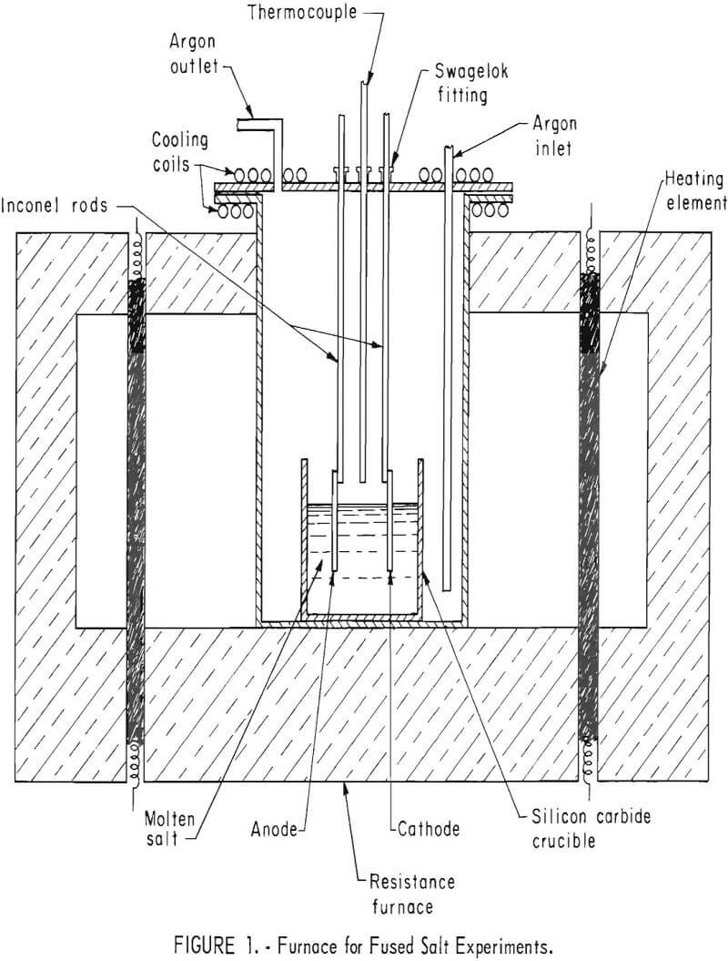
Fused salt electrolyses were performed in an airtight Inconel tube 17 inches long and 6 inches in inside diameter, heated by resistance rods inserted in a refractory brick framework (fig. 1).
A type K Chromel-Alumel thermocouple encased in an Inconel sheath was positioned 1 inch above the crucible. Placing it in the salt might have resulted in corrosion of the thermocouple and contamination of the electrolyte. It was connected to a Honeywell recorder controller to maintain temperatures within ±2° C.
Aqueous electrolytes were used in air. They were heated in a 250-cu-cm Pyrex beaker placed in a 5-gallon tank of stabilized heating oil stirred and thermostatically controlled to ±0.5° C.
Procedure
Cathodes used in aqueous and fused salt electrolytes were prepared by filing off all sharp edges and corners and washing in carbon tetrachloride or ethyl alcohol. They were then pumiced, washed in hot water, and washed in alcohol. In beginning an electrolysis, anodes were lowered into the electrolyte first. The circuit was then completed by placing the cathode in the electrolyte. The distance between electrodes ranged from ½ to 1 inch.
In fused salt experiments the cathode consisted of a metal strip 0.25 inch wide by 0.06 inch thick. The molybdenum cathode used in making a specimen for oxidation testing consisted of a rod 0.125 inch in diameter. For the anode, the shape ranged from an iridium wire 0.06 inch in diameter to a strip 1 inch wide by 0.05 inch thick. The cost of fabricating the larger anode was considerable, so that the wire was used for most experiments. An insoluble graphite anode 0.250 inch in diameter was substituted in some experiments to prevent unnecessarily large amounts of precious metal from dissolving in the electrolyte. The concentration of dissolved metal in the electrolyte was estimated by subtracting gain in weight of cathode from loss in weight of anode. This concentration is an approximation because of loss of some of the anode by decrepitation rather than by dissolution. Before heating the cyanides, the furnace was twice evacuated to 2 inches of mercury and flushed with argon. A flow of gas was then metered in at the rate of 350 cu cm/min. The flow was adjusted to 50 cu cm/min when cooling the electrolyte to room temperature. The oxidation-test specimen was encapsulated by plating one end with the desired thickness of iridium, changing contact points, and then coating the other end plus a small overlapping section of the previous deposit.
Microhardness measurements were made on a Tukon tester with a diamond- point Knoop indenter. Indentations were made on cross sections of deposits, parallel to the substrate.
For aqueous electrolytes, anodes consisted of an insoluble platinum foil ¼ inch wide and 0.015 inch thick. Cathodes were ¼ inch wide and 0.060 inch thick. Both anode and cathode were masked with electroplating tape to give a surface of measured area. Except for the salts of the platinum-group metals, chemicals were reagent grade, and no attempt was made to analyze for impurities.
Electrolysis of Fused Sodium Cyanide Electrolytes
Coatings of Pure Iridium
Iridium coatings were made from several batches of fused cyanides. An electrolyte was formed by passing alternating current at 800 ma/cm² through two iridium electrodes immersed in 150 grams of fused sodium cyanide at 600° C. In 80 minutes, 0.29 gram dissolved, giving a metal concentration of 0.19 percent. A molybdenum cathode was substituted for one of the electrodes, and direct current electrolysis continued for an additonal 6.5 hours. A deposit 2 mils thick was formed at 15 ma/cm². The apparent anode current efficiency was 127 percent, and the cathode current efficiency was 29.6 percent. The metal concentration in the electrolyte increased to 0.7 percent. The electrolyte was green, and the intensity of color increased with increasing metal concentration.
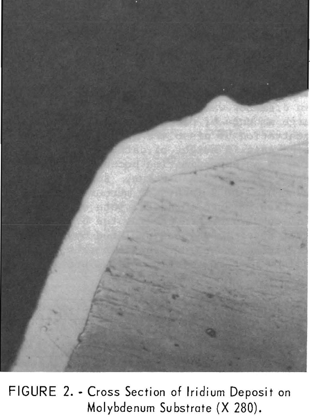
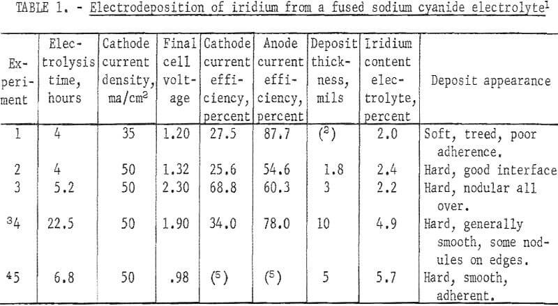
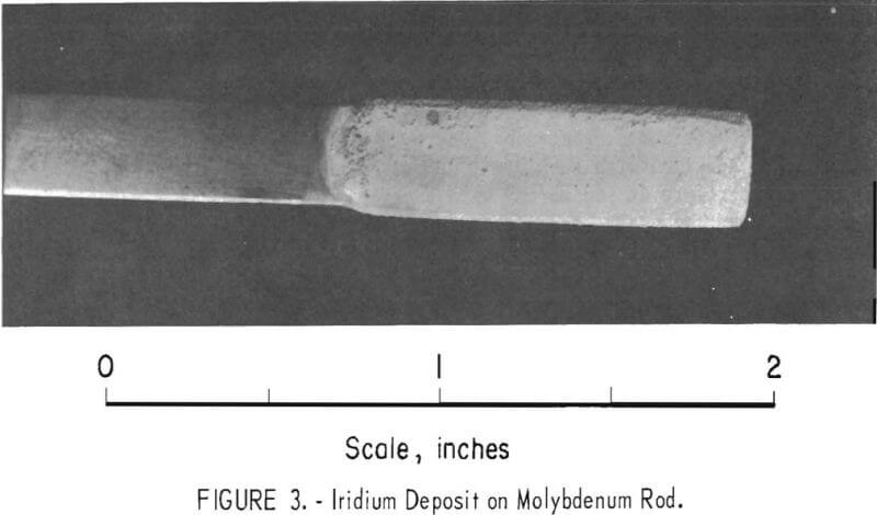
In another batch of fused sodium cyanide with an iridium concentration of 2.0 percent built up by using both alternating current and direct current electrolysis, a cathode current density of 50 ma/cm² yielded a uniform, hard, gray deposit on molybdenum in 4 hours (experiment 2, table 1). Microscopic examination of a cross section of the specimen showed the deposit to be 1.8 mils in average thickness with no voids at the deposit-substrate interface (fig. 2). The microhardness of this coating is 727 Khn100. A heavy deposit was formed in 22% hours on a molybdenum cathode (experiment 4). The deposit appeared nodular on the two edges of the substrate facing the direction of rotation. Nodules were ground off, and the thickness of the deposit was measured with a micrometer and found to be 9.5 to 10.5 mils. It is possible that periodic reversal of the direction of rotation would yield a smoother coating by- spreading the heavier deposit over four edges of the substrate. Cathode current efficiency was 34 percent, and the anode current efficiency was 78 percent. It is sometimes desirable to remove a specimen from the electrolyte periodically for examination. However, with some coatings, an oxide film forms on the deposit when it is exposed to air and prevents the adherence of successive layers of metal. The molybdenum specimen with the 10-mil deposit mentioned above was reinserted in the molten electrolyte at 100 ma/cm² with reverse polarity for 15 minutes. The polarity was reversed again, and electrolysis continued at 50 ma/cm² for 6.8 hours. While molten cyanide appears to have a cleaning effect on metals, the reverse current treatment further increases the likelihood that additional coats of iridium will have good adherence. In 6.8 hours an additional 5-mil coating was formed; or a total of 15 mils. The coating appeared adherent, coherent, and fairly smooth (fig. 3).
There was some anode decrepitation and diffusion of electrolyte through the walls of the carbide crucible during electrolysis from fused salt electrolytes so that it was difficult to maintain precise control of metal concentration. Diffused electrolyte and decrepitated anode material could be salvaged and refined.
In experiments where a graphite anode was used instead of iridium in order to lower the concentration of metal in the electrolyte, an insoluble black crust sometimes formed on the surface of the graphite. It is assumed that this is decomposed electrolyte. A similar crust sometimes formed around the iridium anode if current density exceeded 200 ma/cm² direct current. Because the electrolyte and electrodes were enclosed, it was not possible to view the anode and lower it farther into the bath as it corroded and changed in surface area. A voltage reading exceeding 2 volts indicated that the anode was almost consumed and that this insoluble black crust had formed around the anode. In one experiment lasting 13 hours, both iridium and graphite anodes were used at the same time so that when the apparatus was unattended and the iridium wire corroded completely, the circuit was not broken.
Preliminary results indicate that in the presence of air, only thin deposits of iridium can be formed from a sodium cyanide electrolyte. Although anode current efficiencies were over 80 percent, the color of the electrolyte was pale green, a much lighter shade than in argon atmosphere. This suggests that less of the iridium complex is formed in air.
Alloy Coatings of Iridium With Other Platinum-Group Metals
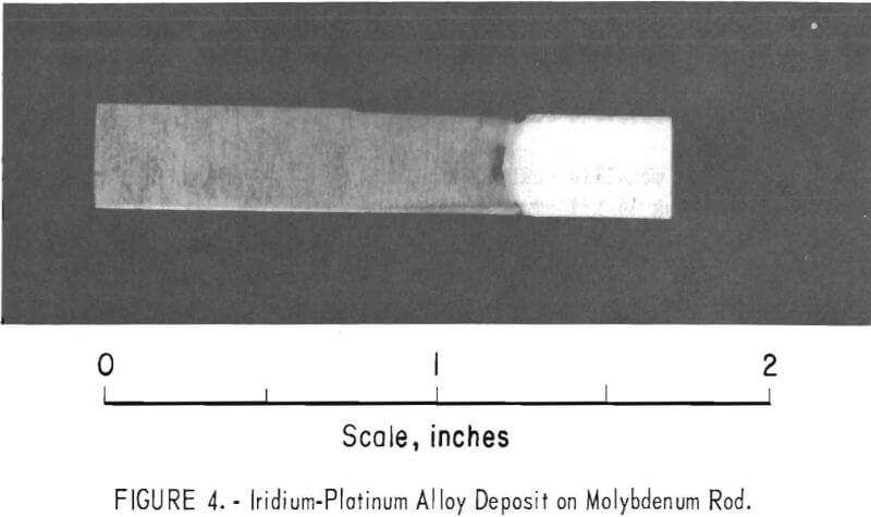
By substituting a different platinum metal for the iridium anode, it was possible to electrodeposit alloys from the iridium electrolyte. After building up approximately 4 weight-percent iridium in a sodium cyanide electrolyte in 18 hours, a platinum anode was substituted. Electrolysis was continued in argon for 1 hour at a cathode current density of 70 ma/cm² and resulted in a smooth, adherent, coherent deposit 2 mils in thickness on molybdenum substrate (fig. 4). The platinum concentration in the electrolyte at the end of the hour was approximately 0.2 percent.
X-ray analysis of the deposit indicates a surface composition of approximately 65 percent iridium and 35 percent platinum. Electron microprobe indicates a platinum content of 25 percent near the molybdenum substrate; this content increases to 35 percent at the surface.
Microhardness values for this coating ranged from 433 to 550 Khn100 – compared with 78 Khn100 for platinum electrodeposited from fused cyanides.
Repeated electrolyses from the same bath for an additional 8.5 hours yielded deposits containing platinum percentages at the surface of 30, 39, 26, 35, 52, 54, and 79. The platinum concentration at the end of the additional 8.5 hours was approximately 0.6 percent. No attempt was made to hold the platinum content in the alloy to a particular value.
Using 50 percent sodium cyanide and 50 percent potassium cyanide in a mixture which contained about 0.8 percent palladium, an alloy was deposited by substituting an iridium anode for palladium. An electrodeposit 2 mils in thickness, containing approximately equal amounts of iridium and palladium, was formed in argon atmosphere.
By a similar process, an 83 percent rhodium-17 percent iridium alloy 4 mils thick was deposited in 7.4 hours after an iridium anode was substituted for a rhodium anode in a rhodium electrolyte.
Electrolysis of Aqueous Electrolytes
Only dark, nonmetallic-looking films could be formed on copper substrates from an aqueous electrolyte described by Ignatova and Vasserman. Their bath contained 6.1 g/l ammonium chloriridate [(NH4)2IrCl6], 14 g/l ammonium fluoride (NH4F), 23 cu cm/l 98 percent sulfuric acid, and 20 cu cm of 20 percent sodium hydroxide. Deposits made at pH 2 were loose and flaky. Pieces of the deposit fell from the cathode. The composition of this material was not established. When the bath mentioned above was acidified to pH 1 with sulfuric acid, the deposits were dark but not loose. Variations in current density from 185 to 300 ma/cm² and in temperature of the electrolyte from 23° to 90° C did not improve the coatings.
A bright, thin metallic coating 4 mg in weight was formed on copper from a solution containing 14 g/l ammonium chloriridate [(NH4)2IrCl6] plus 10 g/l sulfamic acid (NH2SO3H), operated at a current density of 60 ma/cm² and a temperature of 90° C. The deposit was analyzed by X-ray spectroscopy and found to be elemental iridium. The other platinum-group elements were specifically looked for but not detected. The limit of detectability was 0.1 to 0.5 percent. Only thin coatings less than 0.1 mil in thickness could be formed. All attempts to increase thickness such as varying current density and temperature were unsuccessful. Similar results were obtained on platinum and iridium substrates. Repeated electrolyses on top of the previous coating did not appear to increase the thickness of the deposit.
Only dark films less than 0.1 mil thick were formed on copper and nickel cathodes in the MacNamara electrolyte containing 15 g/l chloriridic acid (HgIrCl6). The bath was operated at temperatures of 30° to 90° C and cathode current densities of 50 to 100 ma/cm².
The Conn electrolyte was prepared with 8 g/l iridium chloride (IrCl3·4H2O) and 32 g/l sulfamic acid. Because Conn’s electrolyte produced thick coats only with certain chemicals, he was contacted to find his source of supply. The iridium salt was purchased from the Varlacoid Chemical Co. The iridium anode wire was obtained from Engelhard Industries. Alternating current was applied to two auxiliary iridium electrodes 0.063 inch in diameter, immersed in the electrolyte at a current density of 350 ma/cm² at 75° C for 8 hours to observe the effect on the electrodes. At the end of that time the electrodes lost a total of 1.8 grams. The wires were covered with a dark, adherent film of unknown composition. According to Conn, increased metal concentration due to the dissolution of the iridium was not considered to be of major importance in operation of the bath. He holds that it is the high- current densities achieved by using auxiliary alternating current electrodes that are important for forming the complex.
Electrolysis was continued with the two iridium wire electrodes under alternating current electrolysis, a third iridium anode 0.025 inch in diameter under direct current of 150 ma/cm², and a copper cathode ¼ inch wide and 0.065 inch thick at a current density of 4 ma/cm². The cathode was rotated at 30 rpm. There was considerable gassing at all electrodes. Water was continuously added from a dripping burette to replenish that lost by evaporation and decomposition.
At the end of 23 hours of electrolysis, a bright deposit of iridium approximately ½ mil thick was formed at a cathode current efficiency of 7.8 percent, based on an iridium oxidation state of plus 3. A craze pattern at the surface of the deposit was observed with five-power magnification. Deposition was continued on top of this deposit for 29 more hours. At the end of that time the coating had increased to approximately 1.5 mils in thickness. The final deposit showed many small cracks, most severe in the low-current-density areas of the specimen. This coating would not be expected to offer any protection to the substrate.
Evaluation
A 1/8-inch-diameter molybdenum rod with a surface area of 3.5 cm was encapsulated with an electrodeposit of iridium 4 mils thick and tested for oxidation resistance in a thermobalance. The specimen lost 3 mg, or 0.2 weight-percent, when heated at 300° C per hour to 1,012° C in air flowing at 350 cu cm per minute. The specimen began to oxidize rapidly above 1,012° C and lost 30 mg more when heated to 1,270° C in an additional 185 minutes. X-ray analysis of condensed material on the walls of the furnace showed the presence of a substantial quantity of iridium dioxide. This indicates that 1,000° C may be a practical limit for extended use of iridium in air.
