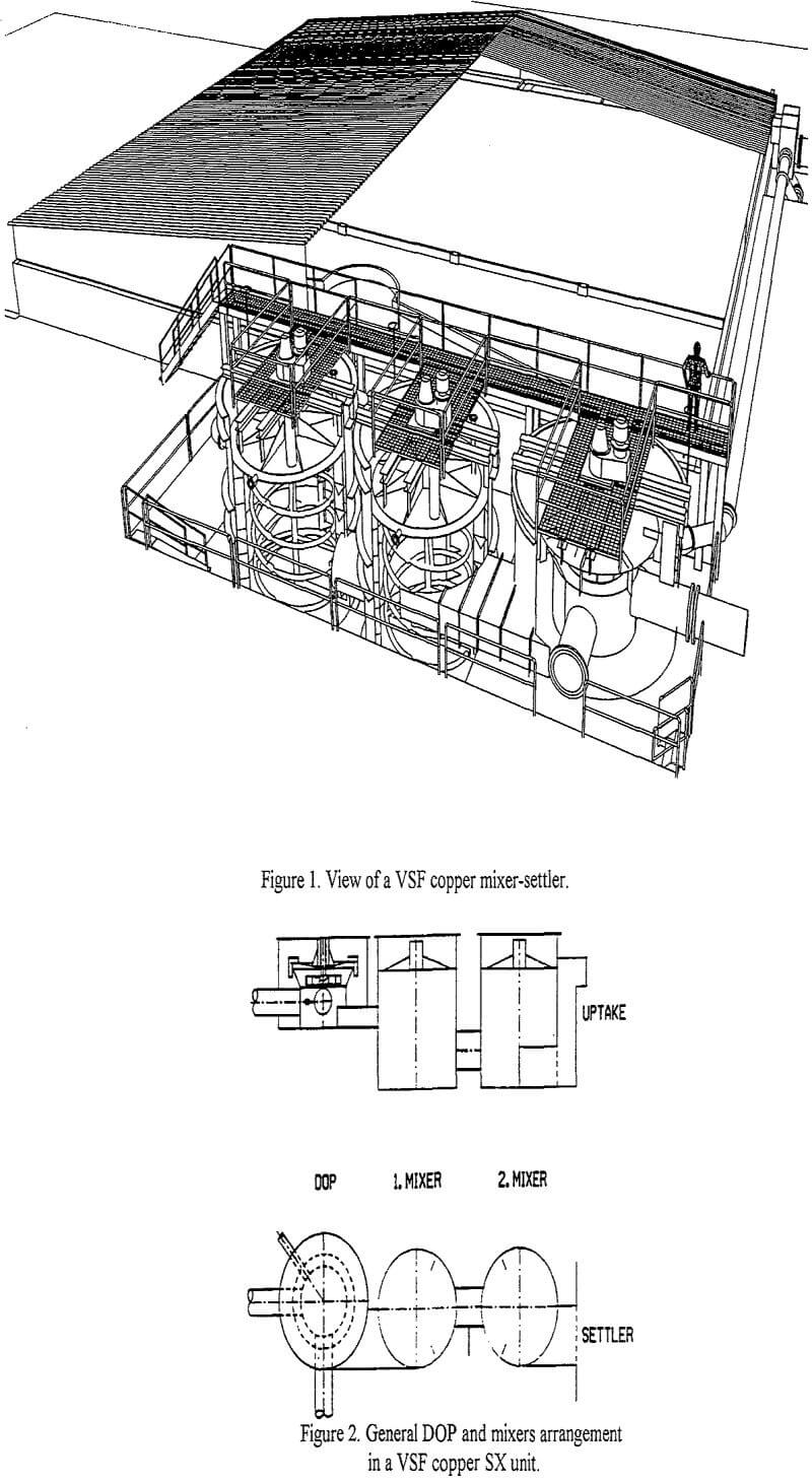
The design of the DOP ensures, that proper pumping with right head-flow characteristics can be combined with a mixing tuned according to the requirements of the liquid-liquid contact to be performed. As this is not easily realized the DOP design has been backed up by Flow laboratory tests to determine the influence of a variety of design details.
A right curvature of the vanes of a double shrouded radial turbine has been found important for a proper performance. The turbine is mounted close to the bottom of a conical casing. By increasing the inlet openings of this bottom and of the turbine itself, and by adding to the turbine an inlet cone profiled to guide the flow, a too intense swirling of the liquids in the turbine vane ducts has been prevented. By these means the flow generated by the DOP has been increased by close to 10 %.
All feed and inner circulation pipe lines are connected to the upper part of a cylindrical boot below the conical turbine casing. This promotes an easy access for all incoming liquids to the low pressure eye of the turbine and further into the turbine itself. The DOP is designed to perform appropriate overpumping to ensure an even flow of solutions in all processing situations.
The turbine rotates in a space close to the surface, and is equipped with an air shield, to which proper baffels are attached in order to ensure that air is not mixed into the dispersion. The shielding top cover extends slightly past the overflow lip of the conical casing, creating a passage for the dispersion flowing out from the turbine space into a surrounding tank cylinder. This is in a normal way equipped with vertical baffles, by which the rotation of the outflowing turbine thrust is suppressed and converted into vertical subflows.
Underlying key design factors
The explanation to the DOP pumping design approach is simple:
- The shearing rate of the liquid-liquid contacting in the mixing space of the turbine has been decreased as far as possible.
- The tip speed of the smoothly shaped turbine can be held reasonable, 3.5 – 4.7 m/s, also in cases, when the total flow has to exceed 2 000 m³/h per unit.
- The induced rotation of the dispersion is suppressed smoothly in a stepwise way using several small vertical baffles mounted both inside and outside the rotation space of the turbine.

A low shear contacting approach in the DOP has been possible thanks to the fact that organic feed lines to the collecting boot below the turbine have been drawn at as high an elevation level as possible. Thus, the counterpressure caused by the mixer or in this case the DOP dispersion, which is heavier than the incoming organic flow, can be decreased.
High feed line levels have been accomplished by installing the turbine closer to the dispersion surface. This design approach has been turned into an advantage by taking into use a carefully designed top cover above the turbine. This cover acts as an air shield preventing air to be sucked into the turbine space. Furthermore, the cover gives also a good support for the baffels mounted in connection to the turbine space.
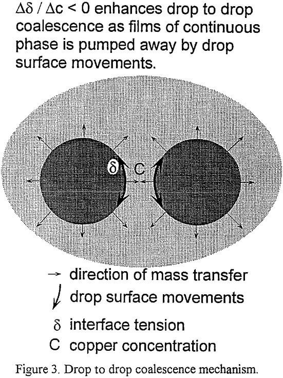
An advantage of a small turbine space, which is not so obvious, is that an intense mass transfer is obtained in that space. This is due to the fact that the residence time in the turbine space is only a couple of seconds, whereas it is close to half a minute in the rest of the DOP tank. Intense mass transfer in turn can be used to suppress the formation of small drops, as described in Figure 3. The so-called “Marangoni” effect (Sawistowski, 1971) keeps the drops relatively big, as the surface movements of the drops, caused by concentration gradients, promotes coalescence according to a drop to drop mechanism. It is also interesting to note that a stepwise premixing in the DOP, is beneficial for the mass transfer itself, as the driving force for the extraction or stripping reaction at hand is kept high.
Head and flow: The total head requirement for properly designed VSF mixer-settlers, based on a pregnant leach solution feed of 1 000 m³/h, is of an order of 400 mm water, as has been shown by hydrolic balance calculations. With this head requirement in mind a series of flow tests was made with three separate DOP units, one laboratory and two industrial units. The turbine diameter of the Flow laboratory unit was 126 mm, whereas the corresponding dimension for a unit meant for a new Harjavalta cobalt mixer-settler was 520 mm, and for a unit manufactured for a Zaldivar copper mixer- settler as large as 1 680 mm. Three flow equations, as can be seen in Figure 4, were generated from these experiments.
Later a complete set of head-flow pumping characteristic curves was generated both for the Zaldivar and the Harjavalta DOP units. As can be seen in Figure 5 for the Zaldivar case, the turbine tip speed is still astonishingly low, only 3.5 – 4.7 m/s in the operation region of such a large equipment. Figure 5 shows also that corresponding values are 2.9 – 3.8 m/s in the Harjavalta case.
The interest in building larger SX equipment, capable to treat an aqueous feed of up to 2 000 m³/h, is growing. With this in mind some additional DOP pumping tests were made using the Zaldivar DOP unit to investigate, how a proportional higher pressure drop on the underpressure side of the turbine will affect the pumping performance. This kind of information will be needed for an evaluation of proper pipe dimensions, especially for the organic flow required. Encouraging results were obtained, as shown in Figure 6. More than 50 % of the total pressure drop could be on the underpressure side, when the total pressure drop was of an order of 1 000 mm water. It can be considered important that this could be obtained using turbine tip speeds well below 5.5 m/s.
Finally some starting tests were made at extreme conditions, at such high underpressures, that those will not occur in any operating plant. As also can be seen in Figure 6, the solution levels stabilized themselves at values corresponding to a total pressure drop of 800 – 1350 mm water, of which 600 – 950 mm water were on the underpressure side.

