The object of the first classification done in cyaniding work was to produce a leachable sand and overflow as small an amount of sand as possible with the ‘slime, which was usually run to waste. In the early days various arrangements of adjustable tank gates were used, and sometimes direct overflow of tanks filled with a rotary distributor sufficed. Later, cone classification, of which the Merrill system, as introduced at Homestake, was probably the most perfect, was adopted. Crushing in cyanide solution, however, first used successfully in the United States by J. M. Henton, added materially to the difficulty of cone work, especially in small plants on soft and variable ores, and in the Black hills at least caused a search for other methods.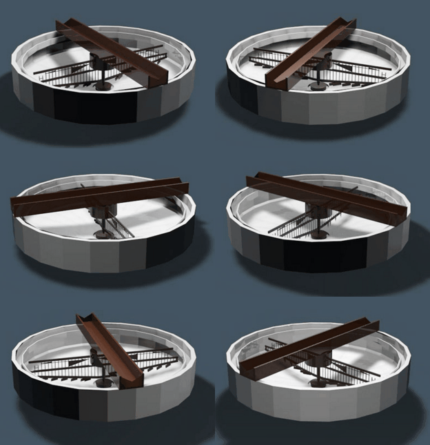
An early attempt to solve the problem that was considered very successful at the time consisted of a box about 3 ft. cube, situated over each leaching tank and equipped with a hinged bottom. The stream of pulp was fed into this box and the solution and slime overflowed until the box was full, when the mill man released the bottom and the sand fell with a splash into the vat below, while another charge was collected. I am told that this method was used in Rhodesia years ago and brought good profit to the inventor. It might be regarded as a poor apology for the double-treatment tanks in use in South Africa and in the United States.
A description of a small plant in the South Atlantic States, which appeared in one of the mining weeklies, shows that the problem was not considered satisfactorily solved at that date. The writer some what proudly told how he had overcome the difficulty of securing clean sand by flowing his pulp into mortar boxes alternately and shovelling the settled sand there from into his leaching vats. These boxes were later abandoned for double cone classification of the sand, which worked well on quartzite ore but gave great trouble on soft material, especially in small plants with irregular feed.
Thickener Design
The cone system was installed in the 100-ton Lundberg, Dorr & Wilson mill above mentioned, but on our ore, which varied from a soft, clayey shale to hard quartzite, it was impossible even with a man constantly watching the cones to get a good leachable sand and avoid overflowing sand with the slime. This resulted in heavy losses through bad leaching of the sands and great difficulties in operating the Moore, process on the slime.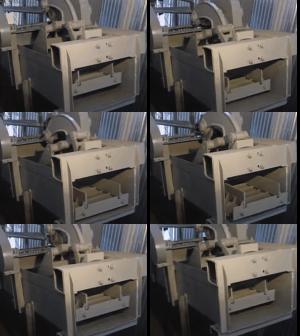
I had felt for some time that a mechanical method of separating sand, that would not require constant attention, was feasible, and realizing that the success of the property, which was operating on a close margin, depended on good classification, proceeded to attack the problem. I knew of the work of George Moore in washing slime from the roasted fine ores at Mercur with a spiral lined cylinder and later with a screw conveyor in an inclined trough, but both methods were somewhat discredited by the abandonment of the Moore process itself at the Mercur plant.
A description by J. E. Johnson, Jr. in the Transactions of the Institute, of a sand shovel he was using to remove sand from a tailings launder at an iron-concentrating mill gave me confidence that I was on the right track. My aim was a settling box with uniform cross-section for settling, from which the settled material could be removed with a minimum amount of slime-bearing solution without disturbance of the surface near the overflow point.
I also felt that, it was necessary to have no submerged parts moving on each other to cause undue wear.
A mechanical rake that would carry the sand up an inclined trough and discharge it above the water level occurred to me as able to fill these requirements and yet give ample space for quick settling at the surface while allowing the maintenance of an agitated zone at the bottom to prevent the slime settling with the sand.
After considerable investigation the motion desired was secured by means of suspending the rake: from cross Lars carrying rollers travelling on suitable tracks, with switches, as shown in Fig. 1. The rollers passed under the switches on the upstroke, but. were lifted on the down stroke and thus raised the rakes over the sand which had been moved forward
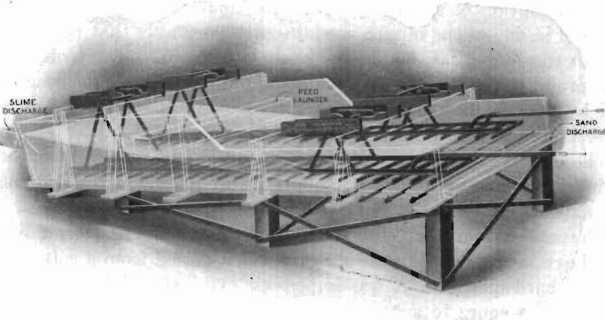
Fig. 1.-The Dorr Classifier (Patented). Original Design
The installation of the machine thus designed made such an improvement in both sand and slime products that our extraction was greatly increased and lost time on account of classification was eliminated. I may say, as a matter of personal interest, that it made the difference between the failure and success of a mill that had a subsequent useful life of nine years and treated profitably ore from which not over $2.50 per ton was recovered.
Mechanical sand separation is a common place thing to-day in cyaniding and may have been used then in concentration and other work. It is of interest, however, to note that one of the best-known engineers in this country told me, later, when he saw the machine working, on his return from South Africa, that if he had seen the blueprints of it he would not have believed it possible that it could give the products it was then making.
Description:
The Dorr classifier has been improved from time to time to meet new conditions and as now manufactured is shown in Fig. 2, which illustrates the standard duplex machine.
It consists of a settling box, in the form of an inclined trough with the upper end open, in which are placed mechanically operated rakes or scrapers for the purpose of removing the quick-settling material from the open end. Each rake is carried by two hangers, one at the sand-discharge end suspended from an arm attachment to a rocker arm or lever, which terminates in a roller. The other depends from a bell crank connected by a rod to the same rocker. The roller is pressed against a cam on the crank shaft.
The rakes are lifted and lowered at opposite ends of the stroke by the action of the cams transmitted through the rocker arms and bell cranks, and the horizontal motion is obtained directly from the crank
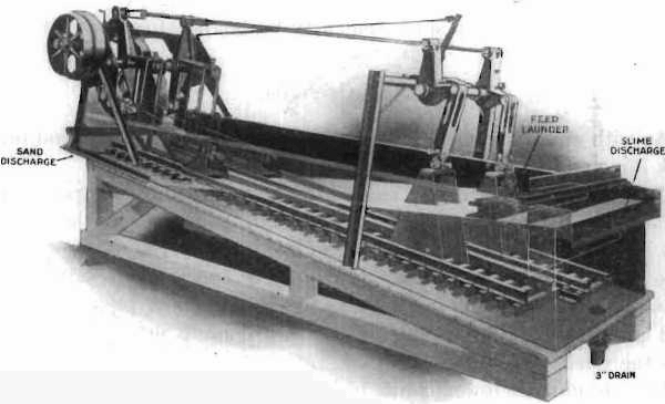
Fig. 2- The Dorr Classifier (Patented) Model “C”
The bell cranks at the slime end are carried by a second larger bell crank held in position by a chain attached to a spool on a worm gear at the head end of the classifier. By this means the rakes can be raised 10 in. at the lower end and operated in that position or any intermediate one. This allows the classifier to be started readily when nearly filled with sand after an unexpected shutdown, and the regulation of the depth of the settling box when in operation to vary the products being made.
The pulp is fed across the settling box as shown and a uniform flow to the lip at the end is maintained while the sand settles to the bottom and is advanced by the rakes until it emerges from the liquid and is discharged with from 20 to 30 per cent, moisture.
The agitation near the bottom of the tank, caused by the reciprocating motion of the rakes, assists in keeping the slime in suspension, but is not normally sufficient to cause fine sand to overflow.
Regulation of Products:
The machine is intended of course to make only two products, and the point of separation can be varied by the following means:
1. The use of the baffle shown, which allows a reduction of the cross section of flow so as to overflow more fine sand.
2. Raising the rakes and so operating them in a shallower tank.
3. Increasing the speed of the rakes until the agitation keeps fine sand in suspension.
4. The attachment of perforated spray pipes to the rakes at a point where they remove the sand from the liquid, allowing a rewashing of the sand and removal of any slime that may be carried down with it.
Cost of Operation:
As with any other machine the costs of operation will depend on the work done and care taken by the mill men.
The only place where wear caused by the sand would be expected is on the bottom edge of the scrapers, and careful measurements have shown that in more than one case four years’ constant service did not remove more than 1/8 in. at this point. This rather surprising result must be due to the scrapers being suspended and the lower edge pushing grains of sand ahead so as to prevent the bottom coming into actual contact with the sand bed.
It is not unusual for machines to run for a year or more without repairs ‘ of any sort being needed, and I know of one classifier which ran for nearly four years with’ repair costs under $5 and a careful examination at the end of the period showed it to be in good condition. I believe an allowance of 0.05c per ton treated for repairs will usually be ample.
Power:
The power required will depend on the load, but tests have shown that ¼ h.p. is generally sufficient.
Capacity:
The capacity of the machine depends, as would be expected, on the nature and dilution of the pulp fed to it and the point of separation desired. The table below showing results at different plants will give the best idea of it.
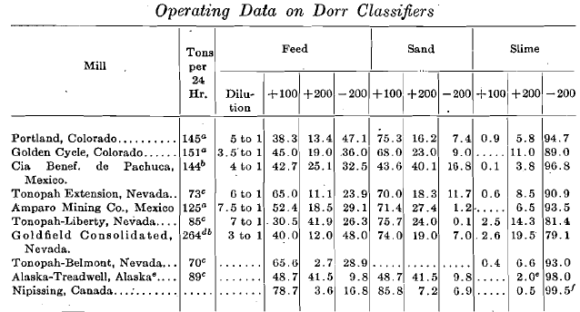
a New ore.
b Includes tube-mill return. Under normal conditions, with a tube mill in closed circuit with a Dorr Classifier, 35 to 50 per cent of original feed returned.
c New ore; tube-mill product returned, but amount not stated.
d 168 tons come from the stamps, the rest being returned from the tube mill.
e Classifiers used in connection with the regrinding of concentrates; rakes operated 24 strokes per minute; 100 per cent of concentrates pass 200 mesh; the 2 per cent is silica from tube-mill pebbles.
f Of this 200 mesh product 15 to 20 per cent is sand; crushing is done in two sets of tube mills; the sand from the first classifiers being reground in closed circuit with tube mills and other classifiers, the combined slime overflows giving the screen test shown.
Uses:
The Dorr classifier was originally designed for the separation of clear slime and a leachable sand, but with the adoption of so-called all-sliming.

Fig.3- Arrangement of Dorr Classifiers and Tube Mills Operating Closed Circuit in the Tonopah-Belmont Mill
treatment in cyaniding its value in connection with regrinding in tube mills was apparent, to all and it came rapidly into use for that purpose also. The advantage of operating a classifier and tube mill in closed circuit with no other means of elevation of the return is appreciated by all practical men. Fig. 3 shows the arrangement of tube mills and classifiers as installed at the Tonopah-Belmont mill.
The use of a Dorr classifier with two or more compartments for washing the sands was early suggested and a double-washing classifier for giving sands an acid bath’was put in use at the Morning mill with tube flotation several years ago.
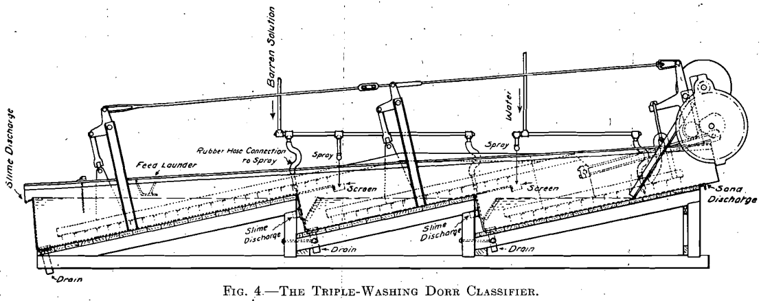
We have carried the idea further and made several triple-washing classifiers for use when sands are to be discharged from gold-bearing cyanide solutions without leaching and must be freed from cyanide and dissolved gold.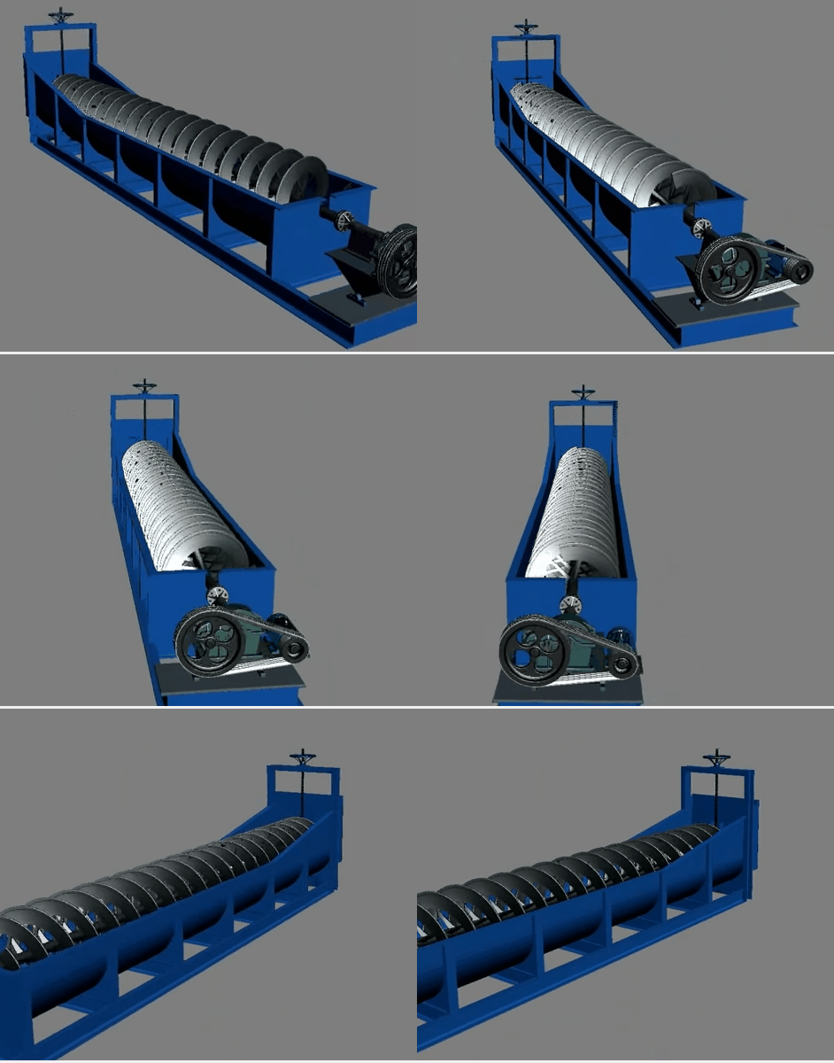
Fig. 4 shows the triple-washing Dorr classifier with pipe connections arranged so as to wash the sands as they come from the first two compartments with barren solution, and from the last with water.
One of these machines following a duplex Dorr classifier has been installed recently at the Hollinger mill to wash the concentrates after they have been reground and cyanided in a tube mill.
The high-grade solution overflowing from the first machine assays $65 in gold per ton and the concentrates are finally discharged with 20 per cent, moisture which assays 16c. per ton; thus giving a dissolved loss per ton of concentrate of only 4c. About 30 tons per day are thus treated.
Later we furnished a series of classifiers to a Pennsylvania company for the purpose of leaching and washing, by the counter-current method, cupreous pyritic residues that had been given a chloridizing roast, but I understand that other matters interfered and their use for that purpose was never thoroughly tested.
Captain Wolvin, of the Butte-Duluth Co., conceived the idea of acid leaching and washing oxidized copper ores in Dorr classifiers from watching them at the Butte Superior mill, and at his request we furnished him with five classifiers for trial and later two more for the same series with all parts subject to contact with the acid made of hard wood. These machines proved most successful, increasing the extraction over the former leaching in vats at coarser mesh at least 20 per cent., and as a result the Butte-Duluth Co has added to its equipment five heavy Dorr classifiers 8 ft. wide by 30 ft. long which I understand will be operated in series and have an estimated capacity of 400 tons.
I believe the results’ of the excellent work done by Captain Wolvin and Mr. Sherwood will be embodied in a paper to be presented to the Institute.
Dorr classifiers have been successful as dewaterers in handling magnetic iron and sulphide concentrates, and are discharging the former with only 12 per cent, moisture.
The Dorr Thickener History:
I was engaged by the Mogul Mining Co. to change the Kildonan mill at Pluma, S. D., from a 100-ton dry cyanide plant into a 300-ton wet-crushing mill following the practice at the Lundberg, Dorr & Wilson mill previously mentioned.
The settling of slime in cyanide work in the United States at that time was an intermittent process usually carried out in flat-bottom tanks, but a few engineers had followed the practice introduced, I believe, by John Randall, of building very large cones and operating with a continuous overflow and intermittent or continuous underflow. We had used’ a 22-ft. and a 20-ft. cone at the Lundberg, Dorr & Wilson mill and appreciated greatly the advantage of continuous thickening, so desired to use the same method at the other plant. The Kildonan had been started , as a chlorination mill, but the property had changed hands and as cyanide ‘was proving successful on Black Hills ores the chlorination barrels were scrapped and replaced’ by some leaching tanks to treat a 20-mesh product. A little later the company was induced to install an aerating leaching process in which the bottoms of the leaching tanks were covered with, perforated pipes and sand was to be leached and agitated at the same time. As might be expected, it was not a success, but added several 35 by. 5 ft. tanks to the equipment.
When I undertook to remodel the mill, as before mentioned, there was no room in it to place the number of large cones that would have been . required, and, as i had-experienced the difficulty of preventing the building up of solids on a 60° slope when making a thick underflow, I sought some other means of thickening continuously. I conceived the idea that it might be possible to operate a mechanism or scraper in a tank at such a speed that it would not disturb the upper part of the tank and interfere with settling and yet would prevent the slime from becoming solid and allow it to be discharged at one point. It was recognized that if the slime did-become-solid-no-mechanism could be-built strong-enough-to-move.it. The design of the machine presented a- problem, in the solution of which I was greatly assisted by L. B. Eames, now superintendent of the Goldfield Consolidated mill, who was an assistant on construction. We decided to utilize one of the 35 by 5 ft. tanks mentioned, after deepening it to 12 ft. Realizing the immense leverage of scraper arms on any shaft, we considered a track on the periphery with a rotating frame traveling, on it from which would depend the rake arms, but finally decided to try the central drive. It was recognized here as in the classifier that stuffing boxes and wearing parts in the pulp should be avoided, and the present arrangement, which seemed the simplest, was adopted.
The use of a 35-ft. tank for the first test was certainly experimenting on a large scale, especially as the first trial thickener represented the only equipment provided in the plant for that purpose. I was prepared, if it had not worked, to use the tank as a settler in another way, which I felt would give as good results as were obtained in practice elsewhere.
We had done considerable good work with diaphragm pumps at Terry, and had found them capable of pumping anything up to small monkey wrenches. I had planned, therefore, to place one or more above the tank and provide each with a number of suction pipes, reaching to the bottom and so spaced that the tank would become virtually a collection of small cones to be pumped from in rotation.
The thickener started off, however, with no trouble and we found that the first speed selected, 1 rev. in 20 minutes, was satisfactory.
Continuous thickening with Dorr thickeners is accepted nearly everywhere now, but its possibilities were not recognized at first. When the first thickener had been operating at the Mogul for several months, a Colorado engineer, manager of one of the best operated Companies in that State, happened to see it. After watching it for some time he was so confident it could not be used for continuous work on his extremely light colloidal slime that he waited nearly a year before trying it. When finally installed it showed an apparent saving in increased recovery and diminished costs.
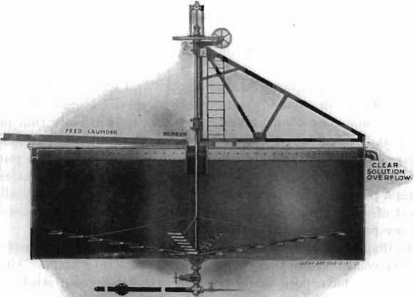
Fig.5- The Dorr Continuous Thickener
When we came to manufacture the machines commercially many improvements were made, the most important being the addition of an overload alarm to give warning when some part of the mechanism was in danger of being strained by the resistance offered by the accumulation of thickened material in the tank.
Description:
The Dorr continuous thickener consists of a slow-moving mechanism placed in a suitable tank, by means of which the operation of settling may be made continuous through the removal of the settled material to a point of discharge and the prevention of its accumulation as a solid in the tank.
As usually furnished, it consists of a central vertical shaft with radial arms equipped to bring the thickened material to a discharge opening at the center by the slow rotation of the mechanism. The thick material may be discharged by gravity at this point into a launder, or piped to the side of the tank and raised by air lift or pump to the level of the overflow or higher.
The machine is arranged for raising the shaft so that the arms will not be imbedded in the thick material if the power should be shut off for any length of time. The shaft can be lowered again gradually while running. Shaft and gear bracket are supported by a bridge over the tank or suspended from the roof trusses (Fig. 5).
In some cases, notably at the Liberty Bell mill, thickeners have been installed driven from below the tank through a mercury, bearing, and proved efficient, although they cannot be raised.
The thin pulp is delivered near the center of the tank in a suitable well with a float to cause minimum disturbance, and the overflow is taken off by a peripheral launder.
The thickened pulp can be accumulated and withdrawn at intervals or a continuous discharge maintained as desired. Nozzle discharge is in use in some concentrating mills where a comparatively thin pulp is desired, and also in one case where a product of only 30 per cent, moisture is being obtained. Many are using diaphragm pumps for this purpose. They have the advantage of ready regulation and require little attention .Having a positive displacement they tend to regulate automatically the amount of solids withdrawn for when the pulp becomes thicker, more solids are pumped with each stroke.
The diaphragms have a life of from two to eight weeks, depending on operating conditions, so that renewal expenses are very small. Although arrangements have been made to change the speed and stroke of the pumps, a pet cock to admit air into the suction has proved most satisfactory as a means of regulation.
Speed:
The thickener has been operated at speeds ranging from 1 rev. in 2 min. to 1 in 40 min. A quick-settling sandy material will offer great resistance unless a comparatively-high speed is maintained, while colloidal slime will give a slightly thicker underflow at a very, slow speed. It will be found when handling sandy material that if the sand accumulates so that it is being moved around the tank by the channel arms as well as being advanced toward the center by the plows the resistance increases rapidly and the speed should be increased.
Power:
This varies with the size of the tank and the nature of the feed. Of course, the motor input is much larger than the actual power consumed, owing to the low load factor commonly used, as it is essential to have power enough to meet an unusual strain. Spring measurements have shown approximately 1/20 h.p. being transmitted to the worm shaft of a 44-ft. thickener handling a classified slime. It would not be advisable, however, to install less than a 1-h.p. motor on a single machine, but 1/2 h.p. each can be allowed when several are driven from one lineshaft.
Repairs:
Normal operation of the Dorr thickener causes no wear except on the worm, and many machines are running to-day that have not cost a cent for several years. On the other hand, if started after a shutdown without
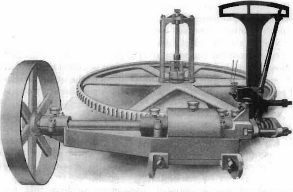
Fig. G.-Overload Alarm and Resistance Indicator on Dorr Thickener, with Arrangement for Raising Shaft while Operating.
raising, a strain of any amount may be given so that the “weakest point,” which I believe exists in everything but the “One Hoss Shay” of Oliver Wendell Holmes, will have to yield. We have attempted to avoid breakage by furnishing a pulley that cannot transmit enough belt pull to do any damage, but the average mill man is likely to use a crowbar to start something without realizing that he can thus apply more force than the belt.
The overload alarm, mentioned before and shown in Fig. 6, is arranged to indicate the resistance offered by the mechanism as shown by the thrust on the worm shaft and to ring an alarm when the load becomes excessive. A solenoid or other means can be used to correct automatically the condition causing the excessive load, by reducing the feed or increasing the underflow. The alarm has proved very valuable, especially on quick- settling pulp, when it is desired to obtain the thickest discharge.
Labor:
The attendance required varies with the regularity of conditions maintained and is usually confined to lubrication once a shift, so that the care of the thickeners, is included in the duties of some man employed principally on other work. At the Anaconda four men per shift are more than enough to care for 160 tanks thickening 26,000,000 gal. per day containing 2,500 tons of solids.
Capacity:
The capacity of Dorr thickeners has been found to be primarily a function of area, although the depth of the tank has an influence depending on the dilution of the feed and the dilution of the underflow desired. With a given area and depth and a very dilute feed and underflow, the capacity depends on the amount of liquid that, can be clarified; i.e. additional solids, but no additional liquid, can be added to a tank already fed to capacity without overflowing slime. On the other hand, with a feed perhaps 8 of liquid to 1 of solids and a’thick discharge of 2 to 1 or less, it will be found usually that additional liquid can be added to a thickener operating at capacity without overloading it, but any addition of solids will cause slime to overflow.
If a plant requires more settling capacity, raising the temperature of the solutions may prove an economical way to add 10 to 20 per cent. The capacity of any filter will also be increased and a higher extraction may pay for the cost of heating.
The table following represents data given me from time to time. It shows the settling area in use per ton in different mills which in many cases were not feeding their thickeners at capacity.
Density of – Underflow:
This depends on the nature of the pulp to be settled and the size of the particles. An argillaceous pulp, such as that at the Liberty Bell in Colorado, although containing a large percentage of reground siliceous material will not settle thicker than 60 per cent, moisture, while a finely ground quartz will give as low as 27 per cent moisture. At the Porcupine- Crown plant, handling a quartz product of 75 per cent. -200 mesh, the average final pulp discharged contained 30 per cent, moisture when the feed was at the rate of 1 ton of solids per day for each 4.7 sq. ft. of tank area.
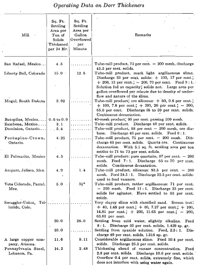
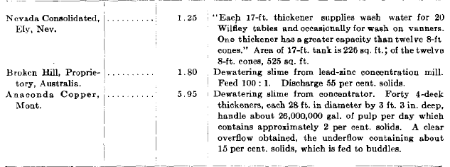
The data given here shown that when pulp is carried in cyanide solution a provision of 5 to 6 sq. ft. per ton for a siliceous tube mill product is ample and from 7 to 15 sq. ft. for a clayey material or classified slime product. When very dilute products are handled the area required is determined usually by the gallons per minute to be overflowed.
Reground pulp, when the original material is not homogeneous, such as an ore containing quartz and some argillaceous material, may be found to have what D. L. H. Forbes has well called a “critical density.” If we attempt to thicken it below this density a segregation may occur and the more siliceous portion of the pulp be discharged while an accumulation of fine slime takes place until it overflows, even though the feed is greatly reduced.
An increase of several per cent, in the moisture of the underflow will cause a return to normal conditions and the thickener will have again its usual capacity.
These conditions have been observed at the Hollinger mill at Porcupine, where a mixture of quartz and schist is milled, but they do not appear to exist at the Porcupine-Crown. I have seen some indications that the slow motion of the arms in the thickener may be of actual service in securing a thicker discharge than could be obtained by undisturbed settling.
Uses:
The Dorr thickener was originally introduced in cyaniding for thickening slime or reground pulp previous to agitation and filtration and came into general use for that purpose. The advantages of continuous thickening were enhanced when continuous agitation was shown to be profitable and the use of a continuous filter made a complete process where actual operating labor was reduced to a very small amount.
Continuous Counter-Current Decantation.-This method for the recovery of pregnant solutions was first operated in this country, I believe, by John Randall in the Black Hills with the large cones heretofore mentioned. Being familiar with his work and the difficulties met in maintaining continuous operation in cones, I recognized that the thickener would make the process feasible, and designed the first plant to use it. This plant has been in successful operation up to the time of writing.
Since then over 20 plants have been erected or are now being installed to operate by this method. Several of them are replacing filters of different types with results apparently satisfactory to their owners, although no detailed figures have yet been published.
The method is especially adapted to the treatment of quick-settling pulp requiring a weak solution for the dissolution of gold and silver. Where pulp cannot be thickened to 50 per cent, moisture or less, or where a strong solution of cyanide is required, it will usually pay to install a filter after the decantation system to reduce the mechanical loss in cyanide and at the same time the dissolved losses which will then be higher.
The subject of continuous decantation is too large to be discussed in detail in this paper, but I hope that a paper will shortly be presented to the Institute covering actual results obtained and discussing it in theory as well as in practice. The advantages of its use in the leaching of copper ores with acid solutions is apparent, as was demonstrated by Dr. Rudolph Gahl several years ago in a test plant at the Detroit Copper Co. I believe that considerable test work is now being done on the same line.
Concentration—The use of the thickener in concentration followed shortly after its wide adoption in cyaniding. The Nevada Consolidated Co. was the first of the large copper companies to use it in place of. cones and obtained good results, as is shown by the following quotation from a letter from the mill superintendent there:
One thickener, 17 by 9 ft. deep, has a greater capacity than 12 by 8 ft. cone tanks, for the reason that there is only 1 unit to watch instead of 12, without the constant result of feed to 12 cones becoming unbalanced. Also the one 8-in. spigot used on the Dorr requires no attention compared with the dozen 3/8-in. spigots on the cones.
It will be noted that the large difference in capacity per square foot is attributed to advantages in regular operation. Under test conditions no advantage has been found in a comparison of the thickener with 8-ft. cones on dilute pulps.
The recent installation of the Anaconda Copper Co. will be described, I understand, at this meeting.
The development of the flotation process has created a further demand for the machine and it has come into extensive use at Broken Hill, and in most of the plants in this country using that process.
The idea of many able concentrating men that the capacity of a settler is in proportion to its peripheral overflow rather than its area, appears, in fact, to have no good foundation where large-sized units are used for completely settling out all solids. One reason for this, I think, is that in such work it is common to have a varying amount of clear liquid always on the surface of the tank. When thickening pulp in an alkaline solution, as in cyanide work, where there is a sharp line between a coagulated slime of definitely heavier specific gravity and clear solution, it is often found that a thickener will have nearly the same capacity if the overflow is taken off by a pipe at one point, instead of by a peripheral launder carefully leveled. With the above conditions there will be a flow of liquid directly from the feed box in the center to the overflow pipe at one side. This will naturally tend to raise the slime level in that path above that in the remainder of the tank, and as a result, the slime-bearing liquid will sink as if it were a non-miscible liquid of greater specific gravity, and the clear liquid from all over the surface of the tank will flow toward the outlet pipe in its place. Samples taken at varying depths have shown almost equal density’ at equal depths at points in the path of such a flow and at the opposite side of the tank.
I do not wish to be understood as recommending the omission of the overflow launder; for when a tank is crowded to its limit it always allows more leeway before the slime overflows, and many operators have found considerable increase in capacity by its use, but cite this as bearing on the relations between capacity and area.
Recent work has shown the advantages of thickening both ahead of, and after flotation to the greatest density possible, using the warm overflow of the final thickeners to dilute the underflow of those ahead of flotation to the proper density for that process. This means conservation of a large percentage of the heat required and also a large saving in oil needed. One plant now following this procedure has found that, whereas laboratory tests indicated that over 1/2 lb. of oil was required per ton, the actual consumption does not exceed 1/8 lb.
Industrial Uses—The thickener has been used successfully in rubber reclamation to settle some finely divided residues and it would appear that there should be many opportunities for its use where operations are on a large enough scale to make the advantages of continuous over intermittent work apparent. At one plant its introduction saved the labor of 12 men.
Acid-proof Thickeners—The absence of submerged wearing parts has made the construction of acid-proof thickeners a comparatively simple matter and we have manufactured them for the Chiquicamata plant of the Chile Exploration Co., and for the Butte-Duluth Copper Co.
The Dorr Tray Thickener:
The tray thickener was designed by me for the purpose of securing large settling area in a comparatively small space. I have not wished to make the invention widely known until we have had ample experience with actual operation under various conditions. Its development has been slow, owing to my desire to determine by actual installations, its limitations, advantages, and the simplest methods of construction.
Description:
The basic principle lies in. the use of a plurality of superimposed shallow settling areas operating with a common mechanism either in
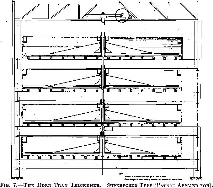
separate tanks, as in the installation at Anaconda, Fig. 7, or with submerged trays in a deep tank, as at the Homestake, Tomboy, and Liberty Bell. The former method presents the advantages of accessibility, but the latter requires less head for a given capacity and gives no loss of
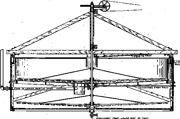
Fig. 8- The Dorr Tray Thickener Submerged Type
mill height for the overflow. It has the merit of offering a simple means of increasing the capacity of any thickener in operation without the need
of adding building, foundations, superstructures or-materially changing launders, etc. We have only gone as far as adding one tray at present in the case of the submerged trays, but have found no reason why two or three should not be used.
Fig. 8 shows our latest type of tray supported, as will be noted, both from the side and bottom of the tank. A cup attached to the rotating shaft carries a rubber gasket which makes contact with the small cone in the center of the tray and prevents passage of the slime to the space below. The thick-slime discharge is carried out at the side of the tank at present. Each settling space has an independent feed but the combined overflow of both is usually taken off at the rim of the tank. It has been found unnecessary to make the tray strong enough to support itself when full with the tank below empty, as an automatic float is provided to connect, the tanks in an emergency.
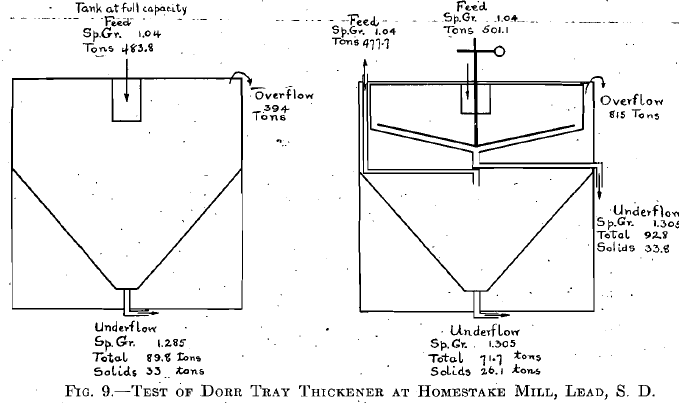
The first test made on this type was at one of the settling plants of the Homestake Mining Co. ,through the courtesy of A. J. Clark, metallurgist in charge, and gave the results shown in Fig. 9. As will be noted, the tray was added to a cone-bottomed tank and the depth is greater than usual. It showed an increase in capacity of approximately 90 per cent.
The first tray to be installed in a Dorr thickener, already in operation, was at the Tomboy last fall and since then they have been added at the Liberty Bell and Tonopah-Belmont. We have also furnished more to the Tomboy.
Capacity:
Careful tests at the Liberty Bell, where a very good form of automatic distributor of pulp is in use, indicate that under conditions there, the tray placed in a 33 by 10 ft. thickener has added 100 per cent, of its settling capacity. The tests mentioned and those made by the Anaconda Co. indicate that the additional capacity to be obtained by the addition of the tray will depend! upon the relative depth and discharge of the tank in which it is placed, the dilution of the feed and the underflow, and the nature of the material settled. It appears conservative to estimate that an addition of from 70 to 95 per cent, can thus be made. It must be recognized that a deep tank has a definite reserve capacity which is valuable when the feed and settling qualities of the pulp vary. If such variations occur during each day a thickener 12 ft. deep might need only the area required by the average feed, while one 3 or 4 ft. deep would have to be able to handle the maximum feed during a period and so might require considerably larger diameter. Mr. Waddell, manager of the Ohio. Copper Co., has told me that the variations in the slime at the Nevada Consolidated were so great that tanks 20 ft. deep were warranted as equalizers. This plant now has eight tanks 50 ft. in diameter by 20 ft. deep besides 13 smaller ones.
The greatest field for the tray thickener is where tanks have to be housed and space is valuable; or heated pulps have to be settled and a minimum of radiation is required.
The Dorr Agitator History:
The Dorr agitator was designed for a mill that I was then planning, but as it was decided to omit agitation at first, it reached the Patent Office before receiving an actual test. The first work done with it on a small scale was by Noel Cunningham, now superintendent of the Hollinger mill, who at that time was doing some test work for Mr. Jones of the Belmont
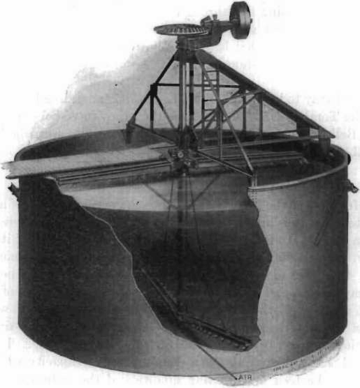
Fig. 10- The Dorr Agitator
and the results obtained showed an average of nearly 4 per cent, better extraction than was made by the Pachuca tank against which it was tested.
The first machine to operate on a commercial scale was installed at the mill of the Hollinger Mines, Ltd., to handle an extremely quick-settling siliceous product which would stall the agitators originally used in 36 hr. It proved entirely successful and was operated for four months when a change to partial continuous decantation made direct agitation unnecessary and it was replaced by a thickener. The second installation of machines proved able to handle a 30-mesh product successfully.
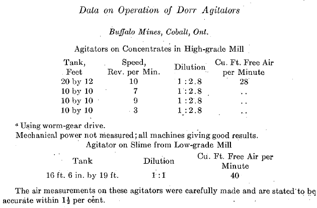
Early on agitators were installed to handle concentrates at the high-grade mill of the Buffalo mines, at Cobalt, and they have given continuously good results on this most difficult work.
Description:
The Dorr agitator as now made consists of a vertical pipe suspended in the center of a tank carrying at its lower end hinged sweeps with
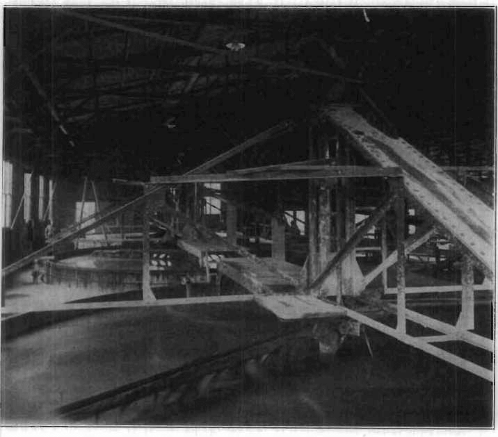
Fig. 11 Three Dorr Agitators, 32 ft. Diameter by 15 ft. Deep at buck-horn Mill Nevada
Scrapers adapted by their rotation to bring any settled material to the pipe. The upper end of the pipe terminates in a head casting carrying two distributing launders and supported by a short vertical shaft with driving mechanism carried by the roof trusses of the building or a special truss over the tank.
A worm and sheaves provide means for raising or lowering the hinged arms at will. Air is introduced into the lifting pipe either at the bottom or by means of a pipe through the shaft, which is then made hollow.
Fig. 10 shows the machine and the method of operation. The Dorr agitator may be briefly described as a Dorr thickener, with only two hinged arms, and a central air-lift pipe with distributing launders substituted, for the central shaft. Fig. 11 shows three of these machines operating in the Buckhorn mill, Nevada.
Speed:
The speed can be regulated to suit conditions. It is usually operated at from 1 to 3 rev. per minute, depending on the size of the tank and nature and density of the pulp being agitated.
Power:
The mechanical power taken varies from j to 2 or 3 h.p. according to the size of tank, speed, nature and dilution of the pulp handled. The air required is from 8 to 40 cu. ft. per minute at 10 to 20 lb. pressure.
Tables below show data as given us by some of the engineers using the agitators. It will be recognized that it is difficult to measure small quantities of low-pressure air and mechanical power and to secure satisfactory data on the operation of individual machines.
The following covers what we have been able to secure on the operation of our agitators:
Nevada Hills, Nevada:
Size of agitator, 30 by 14 ft.;speed, 6 rev. per minute; capacity, 80 tons solids at 1 : 2½;semi-siliceous silver ore, 70 per cent., 200 mesh; mechanical power, 1.4 h.p.; air, 50 cu. ft.
Remarks: “Agitation good; no dead areas; no cost for repairs in 1½ years; practically no attendance.”
Liberty Bell, Colorado:
Ore largely silver, 17 per cent. +100, 70 per cent. —200 mesh; dilution 1 :2 . 15.
Size of agitator, 33 by 11 ft. Air that passes a 3/8-in. hole in 1/16-in. lead gasket at about 19 lb. pressure.
Size of agitator, 17 by 17 ft. Cone bottom (formerly used for Hendryx agitator). Air passing through 3/16-in. hole in gasket; mechanical power about 0.4 to 0.5 h.p. at 8 rev. per minute.
Remarks: Results of five tests showed practically no difference in extraction as compared with the Hendryx.
Tonopah Mining Co., Nevada:
Ore silver, 75 per cent. —200 mesh; dilution 1 :1.
Size of agitator, 36 by 20 ft. Total power for air and mechanical operation estimated at 5 h.p.; speed, 3 rev. per minute; power estimated for paddle-agitator, with four air lifts previously used, 17 h.p.
Remarks: “Results satisfactory in every way.”
Mogul Mining Co., South Dakota:
Siliceous gold ore, 60-mesh product, 7 per cent. +100 mesh; 64 per cent. —200 mesh. ‘Dilution 1 :1½
Size of agitators, 16 by 16 ft. Air that passes 3/16-in. diaphragm at 15 lb. pressure; power at 2 rev. per minute, measured by spring transmission’ to bevel-gear shaft, 1/20 h.p.
Buckhorn Mines Co., Nevada:
Ore, gold, very clayey.
Motor input on three 32 by 15 ft. agitators and lineshaft, 2.82 h.p.; actual output (allowing for power factor) 2.13 h.p. Agitation satisfactory; extraction reported to be better than tests indicated.
Ophir Mines, Colorado:
Ore, gold; 75 per cent. —200 mesh, somewhat clayey; dilution, 1 :1.
Size of agitators, 16 by 16 ft. Air, 8 to 10 cu. ft.; about 20 lb. pressure; speed, 1 rev. per minute; mechanical power under 1/6 h.p. These agitators ran satisfactorily on 30-mesh stamp product.
Renewals:
Any machine of this type can be broken when started with the pulp packed if the arms have not been raised. It has, however; stood up under very hard usage and demonstrated that with very ordinary care there should be no breakage even with quick-settling material. All parts subject to a normal wear will last several years.
Efficiency:
The value of an agitator depends on the cost of making the maximum economic extraction by its use. This will be determined by its cost of agitation per ton per hour and the time required to obtain dissolution.
All the data I have been able to obtain indicate that the cost of agitation per hour is extremely low. Extraction tests that have been made indicate that the rate of dissolution on both gold and silver ores in Dorr agitators, with a uniform although less violent agitation, is at least as rapid as in any other agitators with which it has been compared.
The most favorable conditions for the dissolution of’gold and silver in cyanide solution vary with each ore treated. The maintenance of an excess of dissolved oxygen throughout the whole mass of pulp and the free movement of all particles of solids in the liquid immediately adjacent seem to be the only conditions that can be generally specified.
Definite work both in milling and the laboratory indicate that many ores will give a more rapid extraction and allow the use of a weaker solution when agitated as a dilute pulp of 3 to 1 or 4 to 1, and also cause less chemical consumption of cyanide.
The Dorr agitator with its combination of air and mechanical agitation gives a flexibility that is apparent and it insures keeping‘all the solids in suspension all the time whether the pulp is subjected to a gentle or a violent movement. This is essential especially in continuous agitation.
It will thus be seen that the intensity of agitation can be regulated to suit the chemical needs of the ore being treated, rather than the mechanical necessity of keeping it in suspension in all parts of the tank.
Selective Agitation:
The question of-selective agitation was discussed by Mark R. Lamb1 in the Transactions of the Institute. As used here the expression is taken to mean continuous agitation under conditions which cause the coarser particles of the ore to remain in the agitator longer than the average time of treatment and thus give them the longer exposure they may require to obtain the best extraction.
This can be accomplished readily with the Dorr agitator by agitating at a dilution which allows the coarser material to classify out and discharging the raised pulp near the center while the outflow is taken from near the periphery. It will be seen that if a segregation takes place and the agitator is fed a pulp carrying 10 per cent, plus 100 mesh, the discharge may be only 5 per cent, plus 100 mesh at first. With twice as much inflow as outflow of 100-mesh material it will concentrate in the agitator while gradually increasing in the outflow until an equilibrium may be reached in which the feed and discharge will both be 10 per cent, and the average pulp in the tank 20 per cent., so that the exposure of coarse sand would be approximately double the average.. While this is theoretical, enough work has been done to indicate that the idea can be put to practical use.
Conclusion:
In closing this description of Dorr equipment I wish to express my indebtedness to many friends in charge of the operation of plants using it, who by their constructive criticism and willingness to suggest and try out new ideas have greatly assisted me in making the many improvements that have been added from time to time and overcoming weak points as they have developed.
The classifier, for example, was designed originally to handle 100 tons of ore per day; but more work has been thrust upon it until at the Gold- field Consolidated it has taken care of 260 tons daily, including tube-mill returns. The demand of A. H. Jones, of the Tonopah-Belmont mill, that it be made capable of acting as a sump to take the drainage of the tube mill led to the designing of the present type, Model C, with rakes that can be readily raised 10 in. at the lower end.
It is 10 years this summer since the first of the contributions which it has been my privilege to make to the working tools of the hydro metallurgist was set at work, but a full description of what has come to be known as “Dorr Machinery” has never been published in the Transactions of the Institute, and it has been suggested to me that an account of the same would prove of interest to members, although most of those engaged in cyaniding and concentration are probably familiar with it. The account which I shall give of the development of the machines must be recognized as being written from the viewpoint mainly of my own local experience and not from that of one who was familiar with the general metallurgical practice throughout the world. Most advances in any art are conceived before the time is ripe for their development and any invention which comes into general use will usually be found to have been tried out in a crude way and abandoned more than once. If the early experimenter went as far as the Patent Office, his work may serve no other purpose than to prevent the issuance of the broadest patent to those who later may develop a commercial process.
The cyanide process in the United States early in 1904 was mainly confined to the leaching of dry-crushed ores, both coarse and fine, and sand treatment of tailings from concentration and amalgamation. In the Black’ hills some plants were crushing in cyanide solution, leaching sands and handling the slime by the well-known decantation process.
Filter pressing, in “use for some years in Australia, had been’ tried in several places in this country and the Moore process had been abandoned at Mercur after’ a short run, but was doing good work at the mill of Lundberg, Dorr & Wilson, at Terry, and being installed, at Bodie and the Liberty Bell.
A general feeling, however, still existed that slimes were to be avoided when possible, on account of the losses in treatment and the difficulty of making a good leaching product when they were present in large amounts, especially when the crushing was done in cyanide solution.
The Dorr Hydrometallurgical Apparatus.

