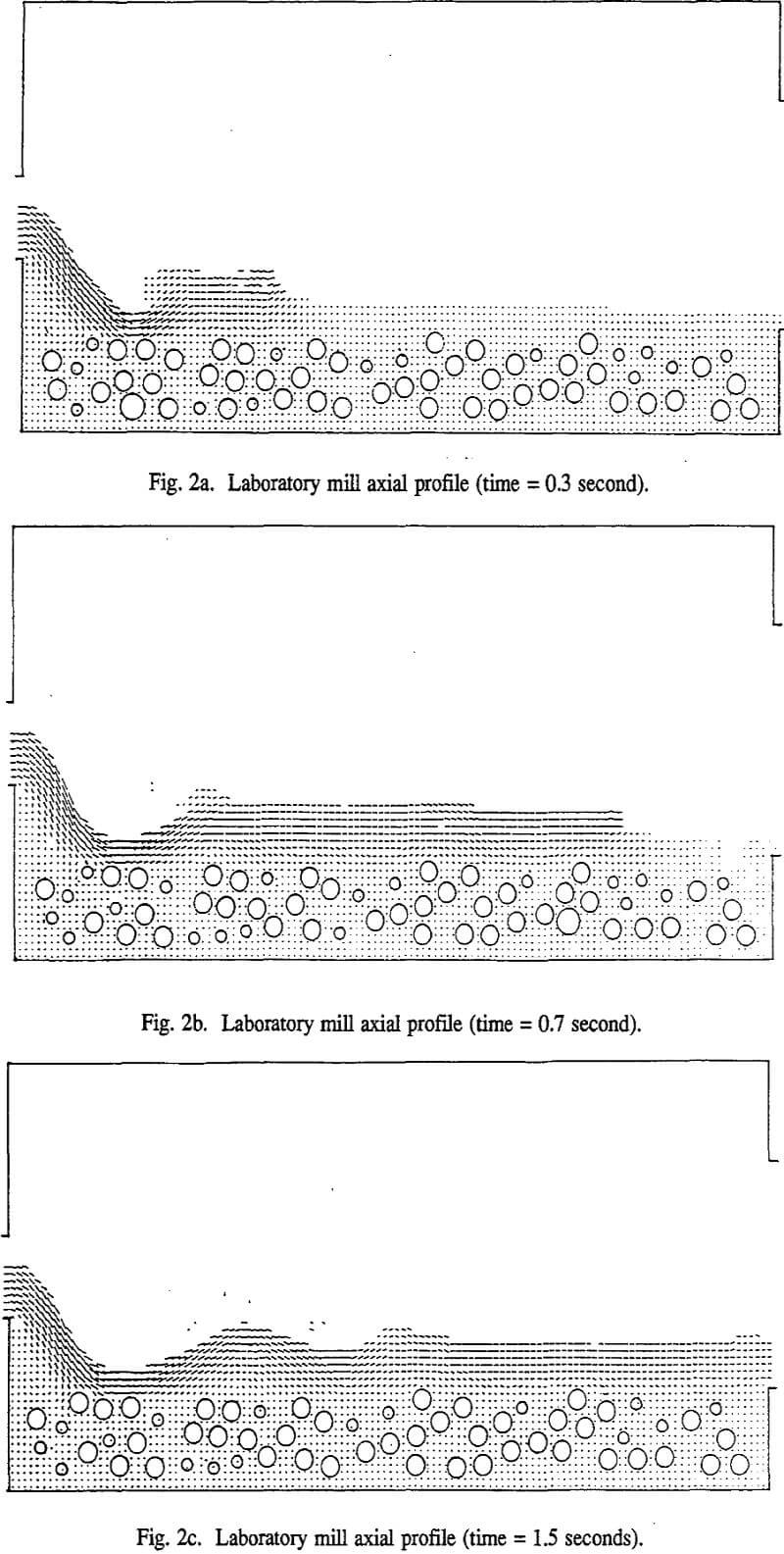
In this work, the slurry flow in the ball mill is solved with Navier-Stokes’ equations and the marker and cell technique (MAC), which tracks the fluid-free surface. Considering different planes in the radial and axial directions, this numerical approach leads to the direct calculation of the slurry velocity profile, mill holdup, and volumetric flow in the ball charge and pool.
Characteristics of Slurry Flow Through Ball Mills
The slurry flow through the ball mill shares some analogies with many of the main classes of fluid flow that have been extensively studied in the field of chemical, mechanical and civil engineering. In fact, one can look at it as a flow through a fixed bed of grinding balls because the slurry has to find its way through the porosity of the ball charge. At the same time, it does share some properties with fluidized bed in the sense that its porous structure is dynamic.
The fact that the slurry flow through ball mills has its properties spread across different types of flow makes it a very complex problem. It is not possible to take advantage of the relations that have been developed for other types of flow. It is not even simple to attempt a combination of these relations in a certain manner that can lead to realistic, if not useful, results. The solution of the slurry flow problem in the ball mill can only evolve from a very novel approach, which takes into account all of the above characteristics. The MAC technique is such an approach.
The Marker and Cell Method
The MAC method was as a tool for numerical solution of problems in the dynamics of incompressible fluid with a free surface. This technique was previously applied to a variety of time-dependent flow problems in several spatial dimensions, with results that agree well with experiments, whenever comparison data were available. The algorithm has been modified to take into account the presence of large numbers of balls whose trajectories are generated by the discrete element method.
The solution technique makes use of finite difference approximations applied to the full Navier-Stokes’ equations:

The x and y coordinate axes are horizontal and vertical, respectively, with the origin located at the lower left of the computing region. The corresponding components of the velocity are u, and v, while Ψ is the ratio of the pressure to the density. The kinematic viscosity coefficient is designated by v. The body force is designated by the constant acceleration components gx and gy.
The occurrence of a dynamic free surface obliges us to consider one important step at each new time cycle, which is the calculation of the new free surface position. This is done by supplying a set of mass-less marker particles whose trajectories follow the motion of elements through the fluid. Marker particles are simply a numerical trick; they do not have any physical meaning, contrary to the ore particles whose trajectories can be calculated separately.
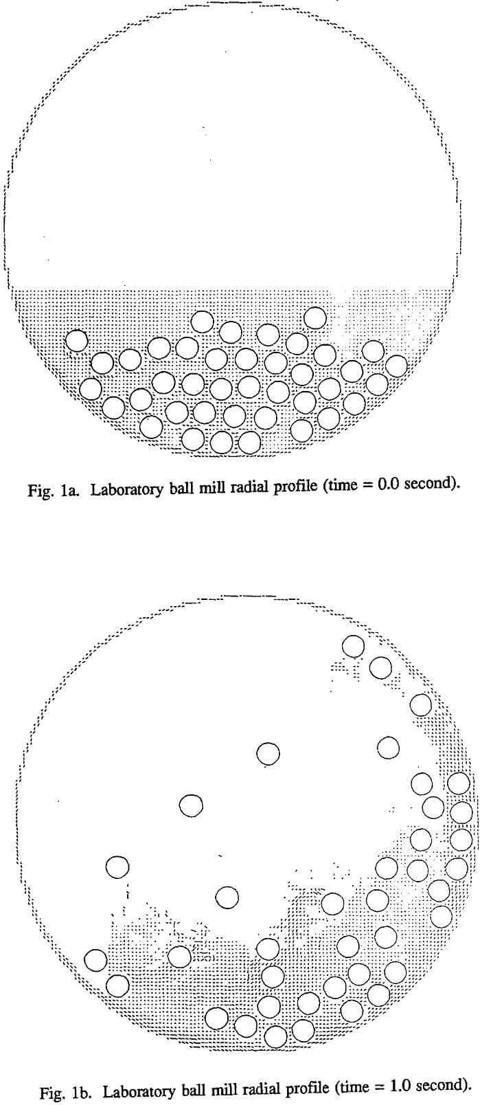
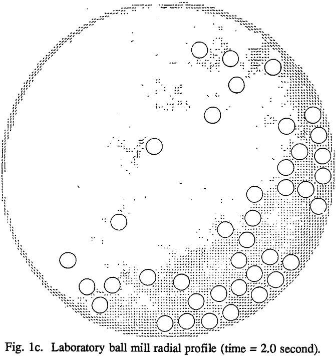
The FLOW computer code that implements the marker and cell technique is still at the early stage of its development. It has been used to simulate a 0.306-m diameter by 0.612-m long laboratory ball mill with 20% ball filling. Steel balls of 19-mm diameter were used in the DEM simulation of ball trajectories. The mill shell is rotating counterclockwise at 73% critical speed. The volume of slurry is 2.7 times the volume of the void in the ball charge at rest. The slurry viscosity is 100 times the viscosity of water.
It can be seen that this code is capable of handling the splashing of cataracting balls in the slurry as well as the effect of the mill shell, which causes the fluid to climb, as can be seen on the right side of the picture. In the beginning, the fluid tends to climb along with the ball charge, but as the simulation continues, it develops its own trajectory. As one can easily imagine, the slurry flow in the ball mill is not a stable laminar flow.


