Table of Contents
 Determine what diameter piping is necessary to obtain sufficient water flow to spray nozzles used for dust suppression. A simplified, diagrammatic method of calculating the flow of water through a proposed system consisting of a supply line and two banks of spray nozzles is outlined.
How it Works
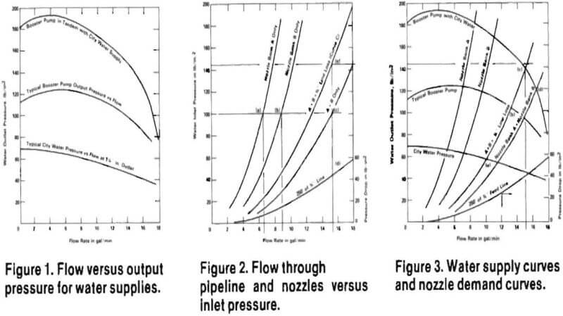
The pressure versus flowrate of the supply at the tapping point must be known or measured. The supply curve of typical city water at a 1¼-inch pipe outlet is shown by the lowest curve in Figure 1. A supply curve for a typical pump fed from an open sump is shown by the middle curve. The combination of these, the supply curve of a pump fed by the city water supply is shown by adding the lower two curves to get the upper curve.
A pump supply curve showing flowrate versus pressure is usually supplied by the manufacturer. The water supply line flow curve can be determined by measuring the time required to fill a 55 gallon barrel at various valve settings to determine flow, and by measuring corresponding pressures at the valve with a gauge.
To see how the curves are used, consider two typical spray bank systems each containing 10 nozzles. Their flow curves are each plotted as a function of inlet pressure in Figure 2. These curves are a function of the number of nozzles and the individual nozzle diameter and type, and are available from the nozzle manufacturer. Using the curves of Figure 2 for example, Bank A delivers 6.3 gallons per minute at 100 psi inlet pressure (Point a), and Bank B delivers 8.8 gpm (Point b). The combined output from A and B would be 15.1 gpm at 100 psi (Point c).
The pipe connecting the supply (booster pump or city water line) to the spray banks usually causes measureable pressure losses. For example, a ¾-inch diameter pipe, 250 feet long, will cause a pressure drop of 20 psi when supplying 10 gpm. The pressure drop can be calculated by using the nomograph that is enclosed with this issue of Technology News. For the example pipe several pressure loss points are calculated using various flows. These are plotted on Figure 2 also.
The loss in the pipe from the supply source to the nozzle bank can be included on the curve for the nozzles. Continuing with the examples from above, with 100 psi at the nozzle inlets we get 6.3 + 8.8 or 15.1 gpm. In order to get the 15.1 gpm and 100 psi, however, we have to account for the 43 psi at 15.1 gpm for the supply pipe (point d). When added to the 100 psi needed for the nozzles, we see that 143 psi at the supply pipe inlet will give the needed flow (point e).
When curves from Figures 1 and 2 are plotted on the same diagram (Figure 3), each of the points where the supply curves and nozzle curves intercept show conditions that satisfy both supply and nozzle requirements.
In other words, the flow and pressure are at the combination at which the pump and nozzles will operate.
For our example, we need 143 psi to get 15.1 gpm through the nozzles. The city water supply alone gives only 57 psi and 10 gpm (point a), the booster pump only gives 105 psi and 13 gpm (point b). The combination will give 140 psi and a little less than 15 gpm (point c). This is very close to the required 143 psi, and would result In a slight flow reduction at the nozzles. If the desired flow is the minimum acceptable, the diameter of the feed line can be increased. For our example, if the pipe diameter is increased to one inch, the nomograph can be used to determine a pressure drop of 15.5 psi for 250 feet of pipe at 15.1 gpm. This is now added to the nozzle inlet pressure drop of 100 psi for a total of 115.5 psi.
Going now to Figure 3, we see this is well below the 140 psi pressure available from the booster pump-water supply combination. Thus the nozzles will deliver somewhat more than the required 15.1 gpm. (The flow delivered will be less than 16.6 gpm, the flow which could be pushed through, the Nozzle Bank A and Nozzle Bank B, with no line loss [point d].) This method is summarized in the following eight steps.
- Lay out a pipe plan such as given in standard textbooks of technical drawings.
- Obtain a water supply curve.
- Obtain a nozzle curve or curves.
- Select pipe diameter for the feed line to the nozzles.
- Add pipe loss to the nozzle curve.
- Plot all the information to produce a curve similar to Figure 3.
- Adjust pipe diameter to achieve desired flow.
- If oversupply or shortage persists, change the pipe plan and repeat the above steps.

