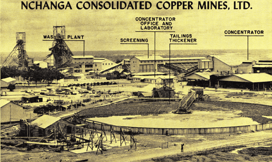
In 1948 Trefoil was privileged to publish an Engineering Notebook Bulletin on Development and Pilot Plant Operations at the Nchanga Consolidated Copper Mines Ltd., Chingola, Northern Rhodesia. This article was authored by Mr. H. L. Talbot, then Consulting Metallurgist to the Anglo-American Group of Companies in Northern Rhodesia.
It is now our privilege to bring our readers up-to-date with a 1962 description of the Concentrator Plant operations.
Since the first article appeared in Trefoil a new concept in the treatment of the copper minerals, oxides and sulphides has been brought about through the progressive research of the Metallurgical Staff of the Concentrator Department.
History
Much of the history of the development of Nchanga Consolidated Copper Mines Ltd. has been published in the Mining and Metallurgical technical press and it is sufficient, therefore, only to mention the fact that this mine is located on the Northern Rhodesian Copperbelt and is the largest single producer of copper in the British Commonwealth and second only to the Chu- quicamata Mine of Chile Exploration Co., which is the world’s biggest single producer.
Geology
The orebodies occur within certain stratigraphic horizons of the Lower Bwana Mkubwa series of sedimentary rocks which rest unconformably on older rocks, believed to be of Pre Cambrian age.
The orebodies occur within the so-called Nchanga West horizon and the Nchanga horizon. The Nchanga West horizon includes the arkoses, transition beds of quartzite and lower banded shales, the Chingola and the River Lode orebodies being in this horizon as well.
The Nchanga horizon includes the whole series of rocks from the chert up to the base of the dolomites, and the Nchanga payable orebody occurs in the felspathic quartzites and upper banded shales of the Nchanga horizon at the base of the banded sandstone quartzites.
Between the Nchanga West and Nchanga orebodies the remainder of the Nchanga horizon consists of upper and lower banded sandstones separated by the shale marker and pink quartzites.
Generally speaking, the shale marker and pink quartzites are a narrow series of beds of good grade ore amenable to metallurgical treatment; the upper banded sandstone is of mineable grade but is difficult to treat metallurgically, while the lower banded sandstone carries low values.
All the ores are of a complex nature, with almost 45 per cent occurring as oxides and carbonates which are, for the most part, acid soluble. The ore contains chalcocite, chalcopyrite, bornite and covellite as sulphides and cuprite, tenorite, malachite, azurite and chrysosolla as oxides, carbonates and silicates and native copper. The sulphides chalcocite, covellite and bornite are products of secondary sulphide enrichment, while chalcopyrite and pyrite are primary minerals.
Concentrator Operations
The ores received into the plant, after conventional washing, crushing and grinding, are subjected to differential flotation for the recovery of sulphide copper mineral for smelting and oxide (or non-sulphide) copper minerals for leaching.
Sources of feed materials to the concentrator are:
(a) Nchanga West orebody
(b) the Nchanga open pit, and
(c) the Chingola open pit.
The first two ores are hoisted to the primary crushing and washing plants via the main shafts, while the third is delivered to a separate circuit.
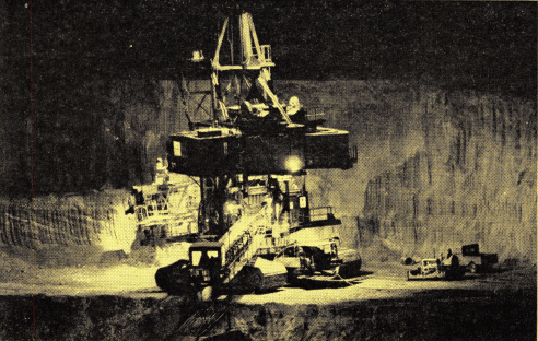
The Chingola open pit mining operation showing the bucket wheel excavator operating at night.
PRIMARY CRUSHING—The ore is hoisted from the two shafts in nominal 10-ton capacity skips and discharged into 1000-ton capacity surge bins at the head-frame, from which it is withdrawn by Amsco feeders fitted with variable speed drives and chain feeders to even out the flow. These feeders discharge on to fixed bar grizzlies with 6″ spacings for removal of fines and the oversize passes to one 20″ and two 30″ gyratory crushers for reduction to 6″ size. The combined product from crushers and grizzlies is conveyed to the washing plant.
WASHING PLANT—The presence of fine slime in the underground and Nchanga open pit ores necessitates the use of a washing plant for its removal to ensure satisfactory operation in the secondary and tertiary crushing and screening sections. Ore is fed to cataract grizzlies adjusted to a 2″ opening and fitted with high-pressure water sprays. The washed oversize passes to coarse ore storage and the undersize to 6′ x 12′ double-deck vibrating screens, fitted with 1″ scalping screens and 5/16″ finishing screens. Additional high-pressure water sprays are fitted above these screens.
The +5/16″ material goes to coarse ore storage and the undersize to 54″ duplex spiral classifiers in parallel. Classifier sands are sent direct to the fine-ore bins over the grinding section, while the classifier overflow is pumped to hydrocyclones for finer separation of the coarser fractions from the slime.
The cyclone underflow is dewatered in a separate simplex spiral classifier and joins the primary classifier sands to the grinding plant bins, while the cyclone overflow is thickened and stored in Goldfields tanks ahead of the flotation plant.
COARSE ORE STORAGE—The washed ore is distributed by means of a conveyor and tripper to an uncovered ground bin having a live capacity of 18,000 tons. Ore is withdrawn through ball and chain control gates to a hopper feeding the conveyor system to the crushing plant.
SECONDARY AND TERTIARY CRUSHING AND SCREENING SECTIONS—The crushing plant consists of four 5½’ standard gyratory crushers and six 5½’ shorthead gyratory crushers in conventional closed circuit with four 4′ x 9′ secondary vibrating screens and eight 5′ x 9′ tertiary vibrating screens. The crushers and screens are housed in separate buildings connected by conveyor belts. All screens are fitted with 5/16″ square mesh screen cloths. Screen undersize is conveyed to the 6,600 ton capacity fine ore bins ahead of the grinding plant.
CHINGOLA OPEN-PIT ORE RECEPTION AND CRUSHING—Ore from the pit, delivered by rail, is dumped into a ground storage bin of 1,800 ton live capacity. A D4 Caterpillar reclaims this ore through two centrally situated grizzlies in the bin floor on to two vibrator feeders which discharge on to a conveyor feeding to a vibrating bar grizzly. The oversize discharges into a 30″ x 18″ jaw crusher, while the undersize is screened to ¾-inch on a 6′ x 12′ vibrating screen. The jaw crusher product and the screen oversize are fed to a 5½’ standard gyratory crusher fitted with a fine bowl and in closed circuit with the screen. Screen undersize is conveyed to a separate mill bin in the grinding plant.
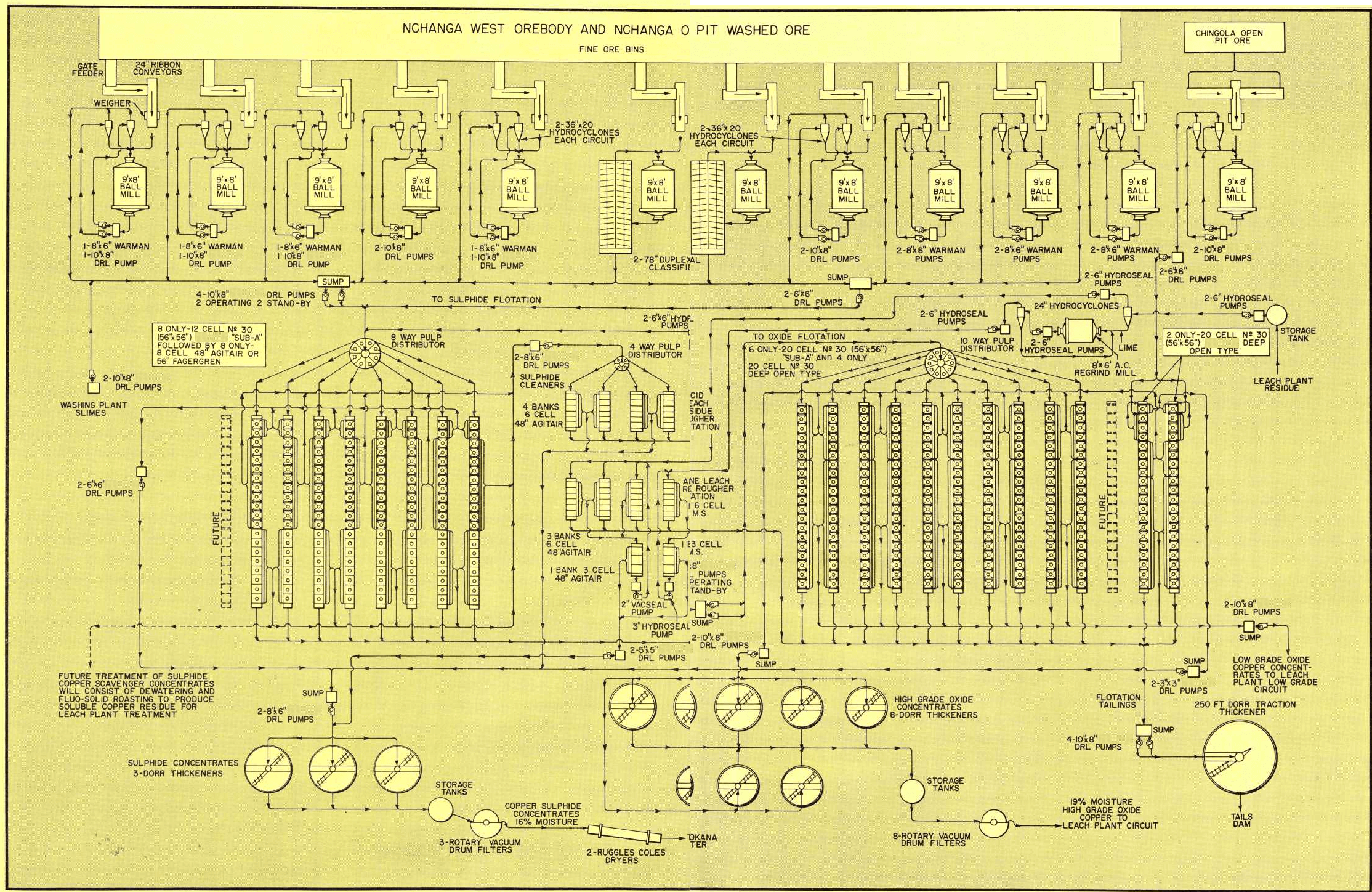
GRINDING—The grinding circuit consists of twelve 9′ x 8′ open end ball mills in closed circuit with twenty-two hydrocyclone classifiers and two 78″ duplex spiral classifiers. One ball mill is in closed circuit with two hydrocyclone classifiers for grinding Chingola open pit ore only. The other ball mills grind washed ore from the Nchanga West underground mine and the Nchanga open pit.
Eleven of the 9′ x 8′ ball mills are Head Wrightson and one is an Allis Chalmers. Each mill is fed with ore at the rate of 42 T.P.H. from a 24″ conveyor ribbon feeder with Foxboro Pneumatic Ore rate controller, to which is coupled, either an Industrial Physics and Electronic Co. or “Adequate” weigher.
Two 36″ x 20° Hydrocyclones with 10″ vortex finder and 4¾” spigot are in closed circuit with each ball mill, except for Nos. 7 and 8 ball mills which are in closed circuit with 78″ Akins Duplex Spiral Classifiers respectively.
The ball mills discharge at approximately 79% solids and this is diluted by water addition to about 65% solids for feed to the hydrocyclones.
The hydroclone underflow product is maintained at 78% solids and the overflow product at from 38-40% solids. The circulating load in the grinding circuit varies from 500-700% depending on nature of the ore being ground.
The ball mills discharge is pumped to the hydrocyclones by means of 10″ x 8″ DRL-C pumps and Warman pumps.
The hydrocyclones overflow is maintained at from 50-55% —200 mesh on the washed ore and at 70-75% — 200 mesh on the Chingola open pit ore.
Flotation
The overflow from the hydrocyclones and spiral classifiers of ball mills Nos. 1 to 11 inclusive, flows to the West and East Side sumps from where it is pumped by 10″ x 8″ DRL Sand Pumps to an 8-way splitter box discharging the feed to the sulphide copper flotation circuit of eight banks of flotation machines at the rate of approximately 70 tons per hour/bank.

The Nchanga grinding circuit consists of twelve 9′ x 8′ Ball Mills in closed circuit with classifiers.
FLOTATION CIRCUITS—The flotation circuits are divided into three sections; two of the sections operate for the recovery of copper sulphides and copper oxides from Nchanga washed ore and washing plant slimes and the third section for the recovery of copper sulphides and copper oxides from the Chingola open pit ore.
Nchanga Washed Ore and Washing Plant Slimes Sulphide Copper Recovery
The sulphide copper recovery is effected through eight banks of 20-cell flotation units. Each bank consisting of twelve No. 30 (56×56) “Sub-A”

Rubber-lined Pumps are used to pump ball mill overflow to cyclone classifiers. Ball Mill discharge is approximately 79% solids which is diluted to about 65% for feed to the cyclones.
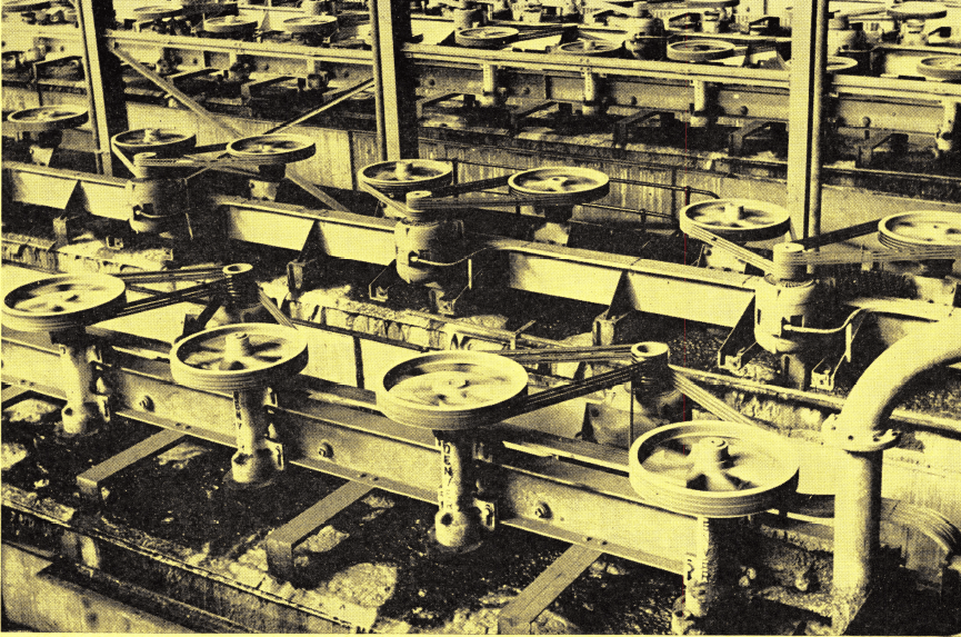
Nchanga, the largest copper concentrator in Southern Rhodesia, uses Flotation—over 335 cells. This photo shows part of the 84 Type “M” Rougher Flotation Machines and 30 “Sub-A” Flotation Cleaner Cells.
Flotation Cells and eight cells of either Fagergren or 48″ Agitair flotation machines.
Each bank operates as follows:
The first No. 30 (56×56) “Sub-A” Flotation Cells produce an acceptable grade of sulphide concentrate, which does not require further treatment, and is pumped by 6″x6″ DRL Pumps to the sulphide cleaner concentrates pump box and thence to the thickeners.
The next 10 cells, No. 30 (56×56) “Sub- A’s” produce a rougher sulphide concentrate, which with the scavenger concentrates from the remaining eight Fagergren or Agitair cells from each bank, are transferred by 6″x 6″ DRL Pumps to the sulphide cleaner circuit.
SULPHIDE COPPER CLEANING CIRCUIT—This section consists of four banks of 6-cell 48″ Agitair type flotation machines. A cleaner concentrate of acceptable grade is transferred by 8″ x 6″ DRL Pumps to the sulphide copper thickeners and the cleaner tailings returned through 6″ x 6″ Hydroseal pumps to the splitter box at head of sulphide copper rougher flotation circuit.
FUTURE METALLURGY—SULPHIDE COPPER RECOVERY CIRCUIT—Metallurgical tests have been made on this circuit and it has been proposed that the rougher sulphide concentrates should be upgraded in the cleaner circuit, and the scavenger sulphide concentrates should be treated by roasting, after prior thickening, to produce an acid soluble concentrate suitable for treatment in the low grade leach plant circuit.
OXIDE COPPER CIRCUIT— The tailings from the sulphide copper flotation circuit are pumped through 10″ x 8″ DRL Pumps to a 10-way splitter box where it is fed to the copper oxides flotation circuit.
This circuit consists of ten banks of 20-cell flotation machines. Six banks are composed of No. 30 (56×56) “Sub-A” Flotation Machines and four banks of No. 30 (56×56) Deep Open Type Flotation Machines (with suspended mechanisms).
This circuit produces a high grade concentrate assaying approximately 16% copper, and a low grade concentrate assaying approximately 2.5% copper.
The high grade concentrate is thickened and filtered in the high grade oxide copper thickeners at the concentrator plant prior to transfer to the leach plant for electrowinning of copper in the leach plant high grade circuit.
The low grade concentrate is pumped to the leach plant where it is thickened and filtered prior to electrowinning of copper in the leach plant low grade circuit.
Chingola Open Pit Ore
This ore is ground and classified in the No. 12 ball mill grinding circuit and the classified pulp for flotation treatment is pumped by 6″ x 6″ DRL Pumps to two banks of 20-cell No. 30 (56×56) Deep Open Type Flotation Machines.
The pulp is fed into the second cell of each bank and a sulphide rougher concentrate is produced from cells, 2, 3 and 4 and returned to the first cell for cleaning. This cleaned sulphide copper concentrate is pumped by 3″ x 3″ DRL Pumps to the main sulphide cleaner concentrate pump box and thence to thickeners. The sulphide copper tailings are treated for oxide copper recovery in the remaining 16 cells of each bank. The high grade oxide copper concentrate produced joins the high grade oxide copper concentrates from the other flotation circuit and is thickened and filtered prior to further treatment in the leach plant. The low grade oxide concentrate joins the low grade concentrate from the other circuit for similar treatment.

Part of the No. 30 (56×56) Flotation Cells in service at Nchanga. This important copper producer has consistently re-ordered Flotation Machines to meet production expansions.
LEACH PLANT RESIDUE—The leach plant residues containing recoverable sulphide copper are pumped from the leach plant holding tanks to the concentrator, where they receive further treatment.
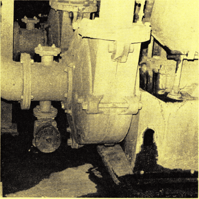
Rubber Lined Pumps, such as this 8″x 6″ pump are used to pump the sulphide tails to the oxide flotation circuit.
The residues as received in the concentrator are classified in a 24″ hydrocyclone, the overflow is pumped to the acid leach residue flotation circuit and the underflow is neutralized with lime, reground and reclassified, prior to further treatment in the alkaline leach residue flotation circuit.
ACID LEACH RESIDUE FLOTATION CIRCUIT — This circuit consists of three banks of 6-cell Agitair flotation machines for rougher flotation and one bank of 3-cell Agitair flotation machines for cleaning flotation. The cleaner concentrate is pumped to the main sulphide concentrate sump box for transfer to the sulphide copper concentrate thickeners and the cleaner tails returned to the head of the acid leach residue rougher flotation machines.
ALKALINE LEACH RESIDUE CIRCUIT—The underflow from the 24″ hydrocyclone which classifies the residues as received from the leach plant is neutralized with lime reground in a ball mill and classified in a 24″ hydrocyclone. The underflow of this cyclone returns to the ball mill for further regrinding and the overflow is pumped to the alkaline leach residue flotation circuit.
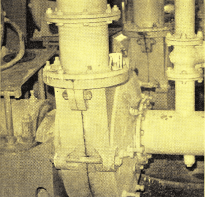
This 10″x 8″ Rubber Lined Pump is used to pump slimes to the mill from the washing plant.
This circuit consists of a 6-cell 48″ mineral separation flotation cell for rougher flotation and a 3-cell 48″ mineral separation flotation machine for cleaner flotation. The cleaner concentrate is transferred to the main sulphide concentrate pump sump for further transfer to the sulphide concentrate thickeners. The cleaner tails are returned to the head of alkaline leach residue flotation cells.
Rougher flotation tails from both the acid and alkaline leach residue flotation circuits are pumped to the final tailings sump for tailings disposal.
Thickening and Filtration
SULPHIDE COPPER CONCENTRATES— These concentrates are, after automatic sampling, dewatered in three thickeners, two 40′ Dorr Tray Thickeners and one 50′ Dorr Thickener. The thickened underflow is stored in two 20′ diameter Goldfields type tanks and filtered on three rotary vacuum drum type filters, (two 12′ x 10′ Fraser and Chalmers and one 12′ x 11′-6″ Oliver). The filtered concentrate (16% moisture) is then dried in two 90″ x 60′ Ruggles Cole dryers with prior underfeed coal stokers. From these it passes to a 900-ton nominal capacity storage bin from whence it is shipped to either the Rhokana Mine or Roan Antelope Mine smelters.
OXIDE COPPER CONCENTRATES— The high grade concentrates are, after automatic sampling, fed to Dorr Type thickeners (40′ and 50′ dia.). The thickened underflow pulp from these thickeners is stored in four Goldfields type (20′-6″ dia.) tanks from where it is sent to eight rotary vacuum drum filters (six 12′ x 11′-6″ Oliver and two 12’x 10′ Fraser & Chalmers). The filter cake, containing 19% moisture, is then sent to leach plant high grade circuit for electro-winning.
Metallurgical Summary
The following is a typical monthly metallurgical report:

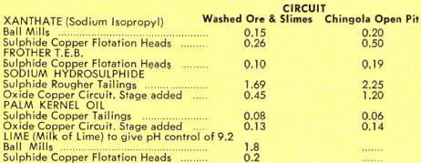
Reagent Consumption
A modern reagent handling and mixing section is maintained. The reagents used and points of addition are as follows. All rates are in pounds per ton (solids).
Lime Plant
The burnt lime and air separated slaked (emergency only) lime in bags arrives in rail trucks.
The air separated slaked lime is mixed in a No. 30 Type M Flotation Machine and the burnt lime is ground in a ball mill. The resultant lime slurry (milk of lime) is pumped to storage tanks from whence it is pumped through a reticulation pipe to points of take-off in the concentrator plant. Pumps used in this circuit are 5″ x 5″ Rubber Lined Pumps.
GRINDING
NCHANGA WASHED ORE
Ball mills—9’x8′ diameter.
Liners—manganese steel grid type.
LINER LIFE IN MONTHS:
End liners with hydrocyclones—5 months.
End liners with spiral duplex classifiers—5 months.
Barrel liners with hydrocyclones—10.5 months.
Barrel liners with duplex classifiers—9 months.
MEDIA: 3″ sand cast manganese steel balls and Raine cast balls. Consumption—2.00 lbs. per ton of ore.
CHINGOLA OPEN PIT ORE
Ball mill—9’x8′ diameter.
Moisture in ball mill feed—8%.
Liners—manganese steel grid type.
End liner—5 months. Barrel liner—8 months.
Grinding media and consumption are the same as for Nchanga washed ore.
CLASSIFICATION
Hydrocyclones—Size 36’x20°
—Vortex finder—10″ diameter
— Inlet area—48 sq. ins. (8″x6″)
—Spigot diameter—4¾” wearing to 5¼”
—Spigot liner—silicone carbide
—Spigot liner life—1100 hours

Rubber Lined Pumps are used extensively through out the Nchanga mill. These 5×5 DRL’s are at the lime plant.

https://www.911metallurgist.com/copper-miningextraction-process-flow-chart
