Table of Contents
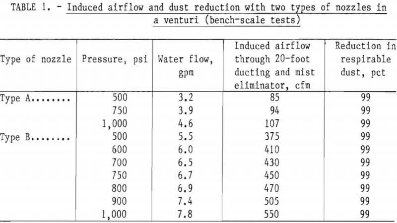
High-pressure shrouded sprays were first tested on a bench to determine air-moving capability and dust collection efficiency. The bench-scale tests indicated that at 500 psi and above, the dust collection efficiency, when sampled downstream of a water eliminator, was about 99 pct for two types of nozzles. However, for the same water flow, the induced airflow was about three times greater in one type than in another. Since the only difference in the nozzles was the spray angle, this factor was important in air movement through a shrouded spray.
Full-scale model mine tests were then conducted to determine the reduction in dust concentration behind the line curtain and at the operator position produced by high-pressure sprays in a shroud. The shroud was mounted on top of the boom of a model continuous miner, and high-pressure (greater than 500 psi) sprays were installed inside the shroud. The inlet of dusty air to the shroud was open toward the face and the outlet toward the exhaust line curtain. The high-pressure sprays were compared with conventional sprays mounted at the head of the continuous miner and directing water toward the face. The difference at the operator position (opposite side of brattice) was significant in that, under certain conditions, with conventional sprays an increase in respirable dust concentration of 471 pct was noticed compared with dry operation due to rollback from face. High-pressure shrouded sprays, on the other hand, decreased the dust concentrations at the operator position (opposite side of brattice) by 28.2 pct.
In response to the Federal Coal Mine Health and Safety Acts of 1969 and 1977, the Bureau of Mines conducted a series of investigations to develop new and improved methods of dust suppression, including the more effective use of water sprays. Initially, the approach was to provide machine-mounted secondary ventilation systems, and one such system was designed for a Jeffrey 100L auger mining machine (appendix A). In use, the dust was reduced by 45 pct; however, this system dragged the exhaust tubing along the mine floor, causing rapid tubing deterioration and production delay while the tube was repositioned for advance. Moreover, the use of machine-mounted fans increased the noise level, making compliance with the noise standards difficult.
Other studies focused on water sprays. An early study of water sprays on continuous-mining machines showed that at a 90-pct confidence level, water sprays on the top of the boom had little effect in suppressing respirable dust. In still another approach, water-powered venturis were designed and used to dilute methane at the coal face. However, their effect on respirable dust suppression under actual mining conditions has not been quantified.
Recent research conducted principally in Great Britain has shown that two high-pressure water sprays mounted on the sides of a short 3- by 10-inch cross section rectangular device will induce an airflow through the device, as well as capturing most of the dust in that airflow. For example, two sprays using a total of 5.5 gpm at 580 psig will produce an airflow of 1,000 cfm.
The objective of the present research is to develop a high-pressure “shrouded spray” system for continuous-mining machines which would produce an airflow capable of drawing in the dusty air from the cutting zone, and have a high capture efficiency for respirable dust. The terra “high-pressure shrouded spray” as used in this paper refers to a spray nozzle operating at or above 500 psi and bounded by an enclosure that could be a circular tube, a venturi, or a rectangular-shaped device. In principle, when such a spray system is mounted on a mining machine at an optimum configuration, a fan-scrubber effect is produced. The simplicity of the approach makes it a viable proposition for use in continuous mining. The absence of a fan, dust collection equipment, water eliminators, etc., reduces the required maintenance. If a closed circuit is established to collect the dirty water and clarify it, small amounts of water can suppress large quantities of dust. The present work, therefore, was aimed at determining the air-moving capacity and dust-suppression capability of shrouded sprays, first individually on a bench and second in combinations of two or three on a simulated mining machine.
Bench-Scale Testing
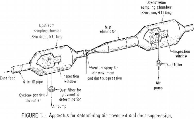
The objective of the bench-scale tests was to obtain guidelines for nozzle selection, air-moving capabilities, and dust suppression efficiencies. Testing of individual sprays was conducted with a dust feeder capable of discharging minus 200-mesh pulverized coal dust (fig. 1). A 4-inch-diam pipe conducted the dust upstream to an 18-inch-diam sampling chamber; 10-mm nylon cyclones were used to draw in respirable dust samples from the upstream and downstream dust clouds.
Two types of spray nozzles were tested in conjunction with a 9-inch-long, 4-inch-diameter venturi (fig. 2). The spray nozzle was mounted upstream of the narrowest section of the throat. The air was moved by the spray as it passed through the venturi throat, creating a low-pressure area within the venturi, and thereby drawing air from behind the nozzle. A mist eliminator removed water droplets that would have affected downstream dust sampling. The respirable dust was collected on preweighed MSA cassettes and then post-weighed to a hundredth of a milligram. The airflow rate was measured by a hot-wire anemometer. Table 1 shows the results when the two types of nozzles
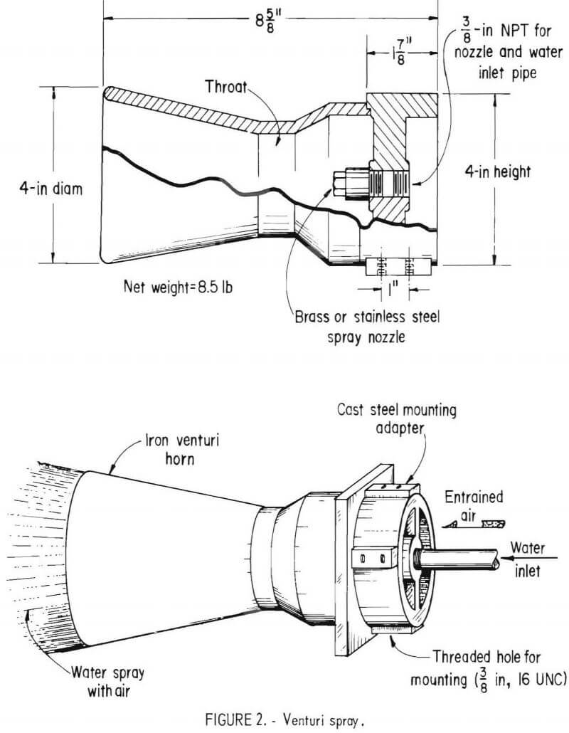
were used. The type A nozzle is a full-cone injector nozzle and has a spray angle of 30°. The type B nozzle has a 45° spray angle and also has full distribution of droplets throughout the full-cone pattern. The airflow through the nozzle would be about one-third with type A when compared with the other at 4.6 gpm (extrapolated for type B nozzle). The difference in airflows would depend on interaction between spray angle and the angle of the venturi horn (fig. 2). These results are similar to those reported by Ralman and Miles.
The dust collection efficiency, however, was about the same (99 pct) at and above 500 psi. The high dust collection efficiencies may be attributable to the water eliminator in addition to the venturi itself since sampling was done downstream of the water eliminator. However, no attempt was made to isolate the effects of either the venturi or the eliminator.
Full-Scale Model-Mine Testing
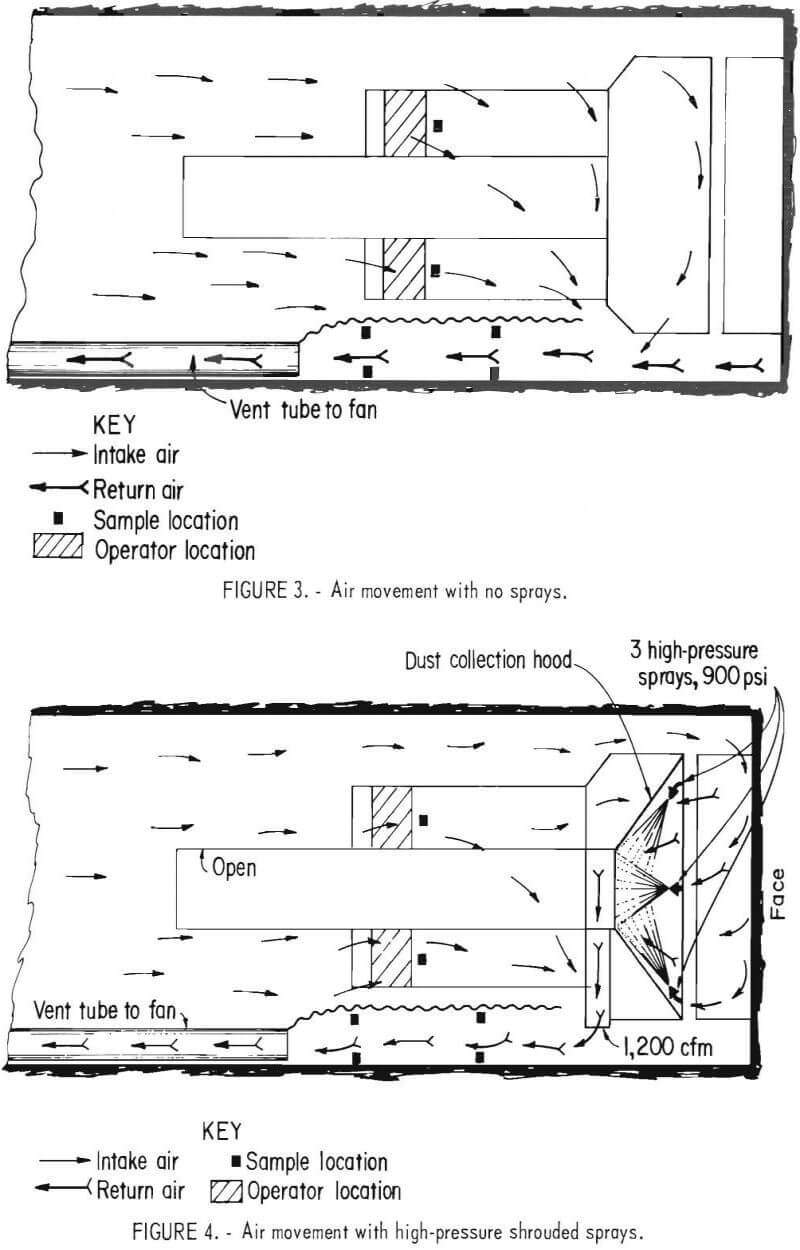
The equipment for dust feed consisted of a vibrator feeder for fine (minus 1/8-inch) Pittsburgh seam coal and a commercial pulverizer. The very fine dust coming out of the pulverizer had a size distribution similar to that of airborne coal mine dust. The dust was pulled in by a 600-cfm blower fan discharged at the front end of the model entry. The main ventilation for the entry was activated by a Joy 10 hp axial-flow fan. The full-scale Joy 12 CM model was located in the 14-foot-wide by 6-foot-high entry. Figure 3 shows the arrangement and the air movement when no sprays were used. Figure 4 shows the arrangement for the high-pressure shrouded spray system. The ducting formed a triangle, with three spray nozzles located at the face side of the triangle and directed toward the apex where the auger support frame joins the main frame. Most of the water was discharged at the throat where the conveyor would carry coal and water to help wet the coal. A 14-inch-diam fiberglass ducting was used to convey the cleansed air to the curtain side. In an actual mining situation, this ducting can be so installed as to discharge the air in either direction. High-pressure shrouded sprays (900 psi) changed the air movement as shown in figure 4, moving the dust-laden air from the vicinity of the face and bringing down respirable and float dust contained in the air. The cleansed air was discharged near the line curtain.
The test procedure was to measure the total amount of respirable dust conducted to the face return. Eight personal samplers were used with
10-mm nylon cyclones. Two rectangular arrays of four cyclones each were hung 4 feet apart. Two cyclones from each array were sampling respirable dust for the dry run; the other two cyclones in the array were used for the wet run. The total mass of respirable dust in the return was collected on the four filters for the dry runs and wet runs. The dry and wet runs were alternated to even out any variations in dust feed rate. Since airflow was constant for the duration of the runs, the percentage dust reduction R of a spray system relative to a dry system is given by
R = (1 – w/d) x 100,
where w and d represent the total respirable dust measured in the return during wet and dry runs, respectively.
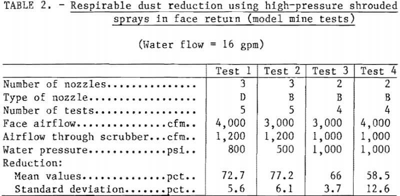
Table 2 shows the dust reduction efficiency behind the line curtain of the face return for two types of nozzles and two airflows. The air movement induced by the sprays varied, depending on the pressure and type of nozzle. Also, the differences in the rates of air movement caused by spray nozzles is not a simple multiple of the quantities obtained in the bench-scale tests.
The reason for the discrepancy is because of the differences in the configuration of the shroud. Also, the dust collection efficiency will necessarily vary. Tests run with two nozzles and at 16 gpm at a higher pressure gave a lower percentage of dust reduction than three nozzles and 16 gpm at a lower pressure for the face airflow. Reduction tends to decrease as the face air-flow increases (tests 3 and 4). This may be due to less efficient capture at the inlet to the sprays.
Another series of tests was run to compare the effects of 20 conventional sprays (type C nozzles) with those of 3 high-pressure sprays (type D nozzles), both of which were mounted at the front of a continuous miner. Type C nozzles provide distribution in a hollow-cone pattern (0.95 gpm at 100 psi); type D nozzles provide distribution in a full-cone pattern (1.9 gpm at 100 psi). The tests (table 3) were run for 20 min for each type of spray.
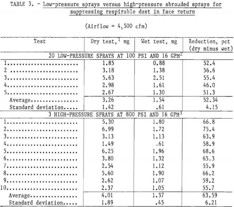
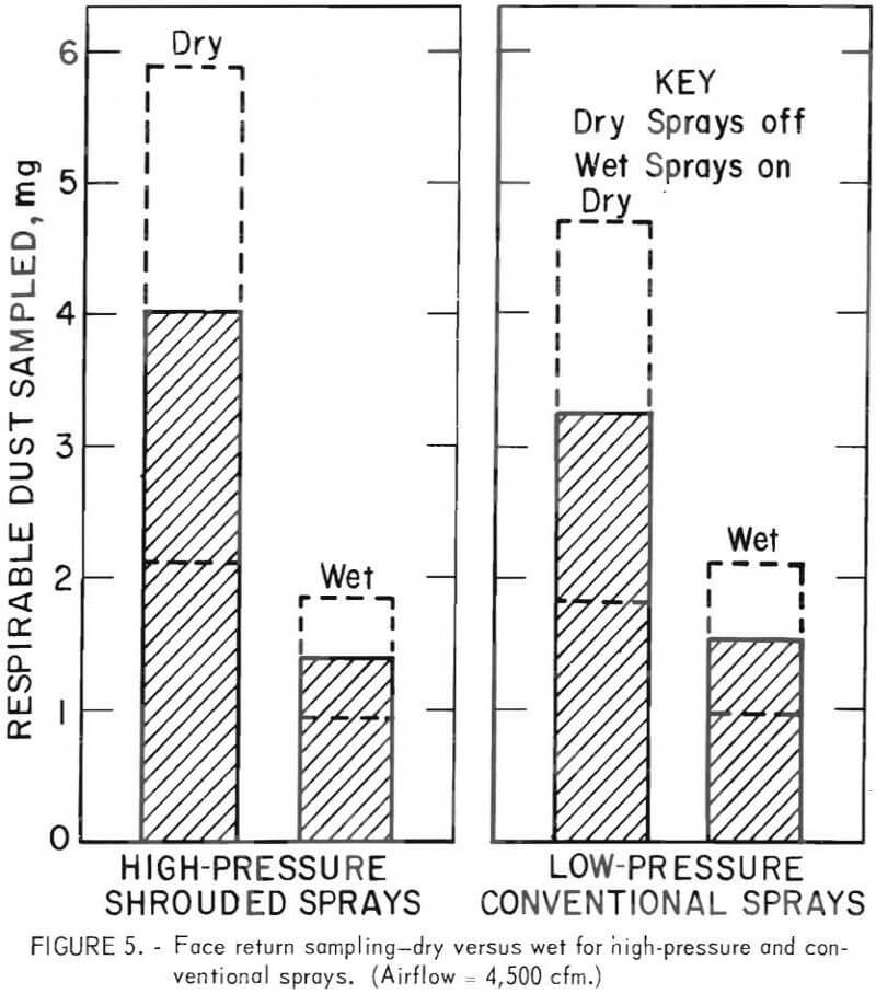
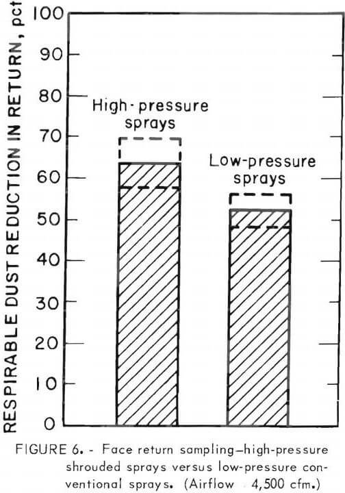
Figure 5 gives the dust weights in the face return for the high-pressure and conventional spray tests. (The broken lines represent 1 standard deviation from the mean.) A reduction from 4.01±1.89 mg to 1.37±0.45 mg was obtained for high-pressure sprays when compared with dry tests. A reduction from 3.26±1.42 mg to 1.54±0.61 mg was obtained for conventional sprays. Figure 6 expresses the reduction as a percentage, when comparing the high pressure with the conventional spray (65.59+6.21 to 52.34±4.15 pct).
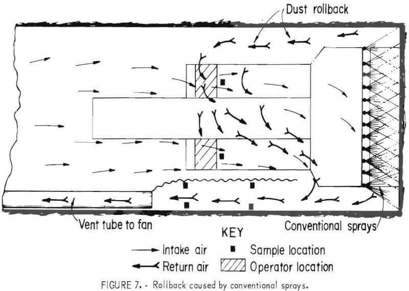
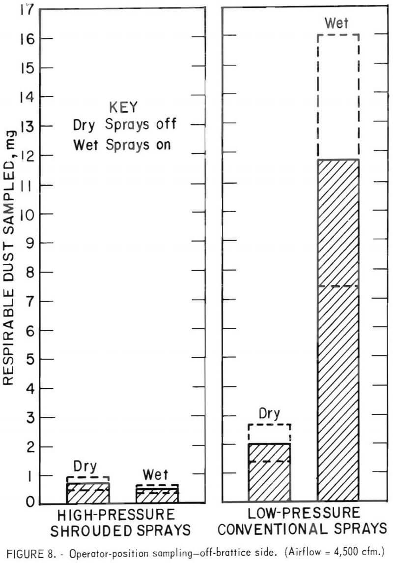
Dust concentrations were also measured at the miner operator position to determine the effect of rollback due to conventional sprays (fig. 7). Figure 8 shows that with high-pressure sprays dust weight at the operator position
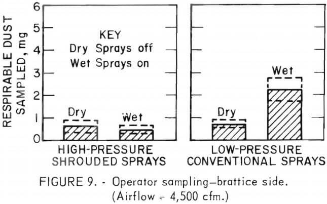
 on the off-brattice side was reduced from 0.69±0.30 to 0.4710.19 mg, a decrease of 28.2 pct. However, when the conventional sprays were tested, the rollback caused by sprays increased the dust levels from 2.5±0.63 to 11.714.31 mg, an increase of 470.7 pct. Similarly, at the operator position near the brattice (fig. 9), high-pressure sprays reduced the dust weights from 0.71+0.21 mg to 0.51±0.15 mg, a decrease of 31.9 pct. For conventional sprays, there was an increase from 0.7210.14 mg to 2.2010.54 mg, an increase of 205.6 pct. Since it is the operator position that is important for a compliance, it is significant that the turbulence and rollback of dusty air caused by open sprays are avoided with high-pressure shrouded sprays.
The 600-cfm blower fan feeding the dust-laden air added that amount of air into the system and, therefore, the pattern of air movement would be different from that of actual coal mine face of similar
 dimensions. However, work conducted by FMA Inc. with methane, indicated similar airflow movement, even at higher water pressures of 200 psi for conventional sprays.
Conclusions
A shrouded high-pressure spray system was machine-mounted in a fullscale model mine. The spray system sucked the dust away from the face and knocked it down into the shroud. Dust suppression at the operator position was much better than with conventional sprays mounted at the head of the miner. The avoidance of rollback caused by such conventional sprays reduced the respirable dust exposure at the miner operator position.
In addition, the absence of fans, mist eliminators, and dust collection media makes the system very simple to operate and maintain. The spray units are small enough to be located close to the face. Retrofit arrangements can be made for any operating continuous miner.
However, if larger exhaust face ventilation quantities than the 4,500 cfm used here, are encountered in real raining situations, the capture efficiency will be lower. Also, capture efficiency will be considerably lower if blowing ventilation is practiced at the face.
Machine Mounted Ventilation System
to reduce dust on a Jeffrey 100L Auger Miner
The study was conducted in Southern Appalachian Coal Co.’s Lens Creek Mine, Marmet, W. Va. Mining was going on at 4 South section where the seam height was 36 inches and the rooms were 30 feet wide. The coal was very dry and the wetting arrangements for the auger miner consisted of 15 spray nozzles mounted on a probe that could be extended between the augers. The machine-mounted ventilation system was designed by the Bureau and the dust collection hood was mounted on top of the auger miner. The hood was shaped like a “Y” to gather dust from the front of the machine and from around the augers. An expanded metal screen (not shown in figure) prevented the large pieces of coal from entering the hood (figs. A-1 and A-2).
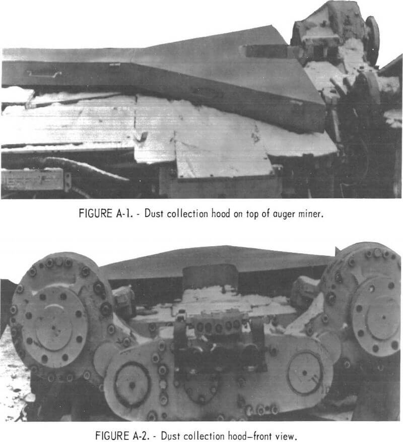
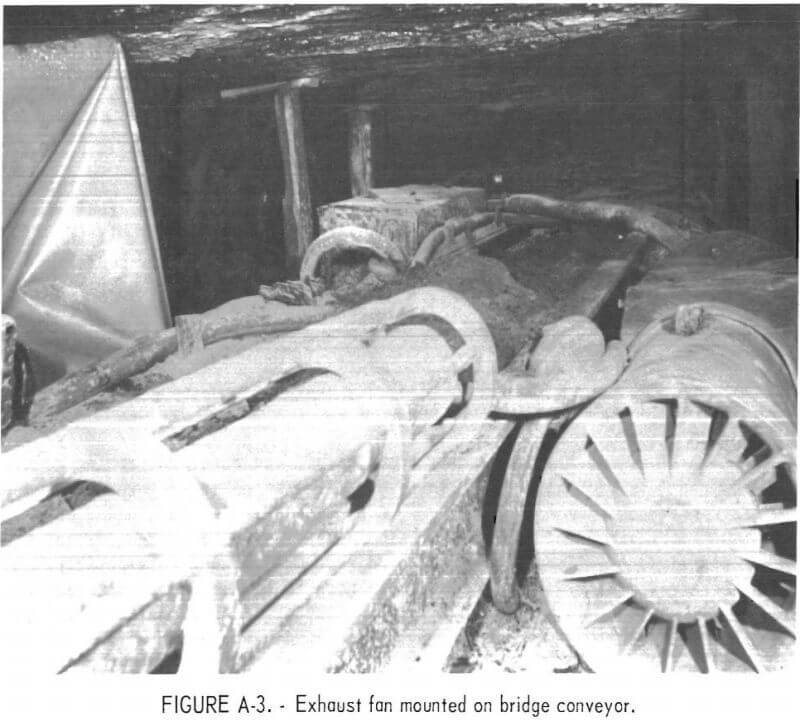
The cross-sectional area of the hood was such that a velocity of 2,000 fpm or less was maintained. Initially the rear end of the hood was connected to one Joy Model 5112 fan by wire-wound 12-inch-diam tubing. When very little resistance was included in the system, this fan had a capacity of 2,000 cfm. However, the high resistance created by the hood in the front and spiral-wound tubing in the back reduced the airflow to 1,500 cfm. By mounting two fans in parallel, about 3,000 cfm of airflow was circulated from the augers to the face return. The total face airflow was about 6,500 cfm. Therefore, the fan handled about 45 pct of the face airflow. Since the use of a flooded-bed scrubber reduced the airflow through the Joy fans even further, it was decided early in the program to eliminate the scrubber and discharge the effluent in the return. Figure A-3 shows one Joy 5112 fan as it was mounted on the side of the bridge conveyor. The second Joy fan was located next to it and to the side. Flexible 12-inch-diam tubing was used on both sides of the two fans, with the suction end going to the hood and the discharge end to the face return behind line curtain.
The test procedure was to measure the respirable dust in the return behind line curtain when the auger was raining at the face. The curtains were set up as in figure A-4. Simultaneously, respirable dust was also measured in the air coming out of the fans. A light-scattering dust monitor capable of
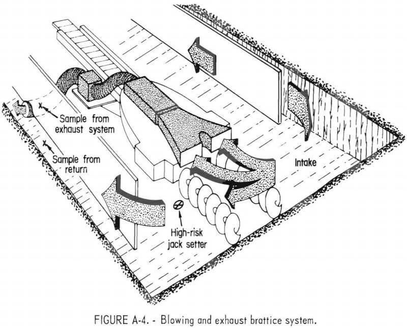
indicating dust concentrations in real time was used. A cyclone classifier removed the nonrespirable fraction of the dust. The total mass of respirable dust in the face return was calculated by multiplying the average concentration in the face return by the airflow by the time of sampling. Similarly, for the fan return, the total mass of respirable dust was calculated. The time of sampling depended on the activity going on at the face. If the machine was idle, then no readings were taken. Readings were taken simultaneously in the two returns for the same time interval. Capture efficiency is the ratio of total respirable dust passing through the fan return to the sum of that passing through the face return and the fan return.
Results and Conclusions
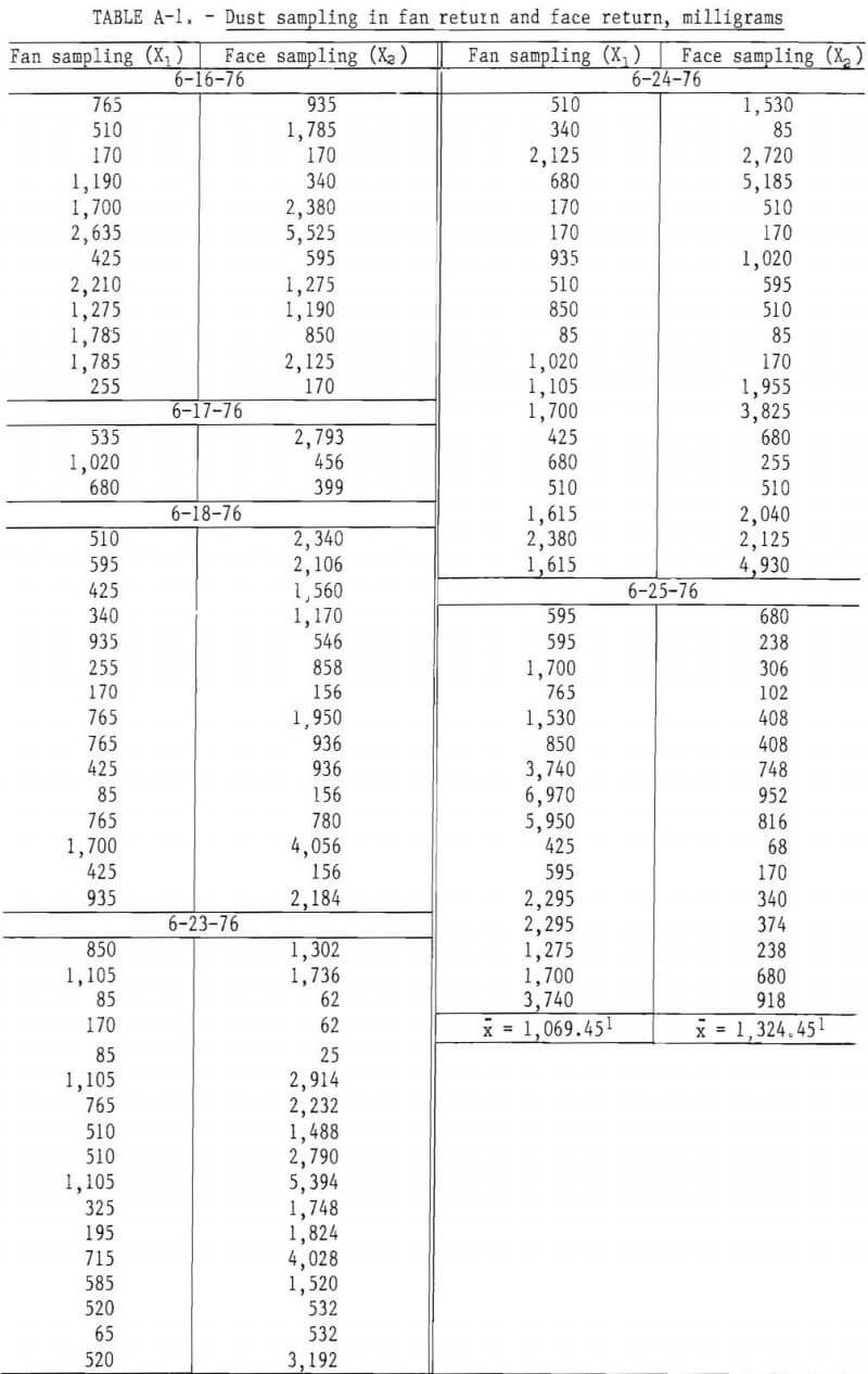
Table A-1 shows the results under production mode with water sprays working. An average capture efficiency of 44.65 pct was obtained for the 6 days but the range is from 23 pct to 82 pct. The variation in efficiency was due to the variations in the distance of the blowing curtain and exhaust curtain from the face. When the blowing curtain lagged behind by 20 feet or so, the capture efficiency of the machine-mounted system increased considerably. A zone of near-stagnant air was highly conducive to high capture efficiencies. However, the system is not practical because of the operational constraints. Significant delays were caused by moving up the discharge tubing as the mining advanced and dragging the tubing along the mine floor resulted in severe abuse and rapid deterioration. Increase in noise due to additional fans was not welcomed. It was concluded that a wet-head retrofit system would be more suitable.
