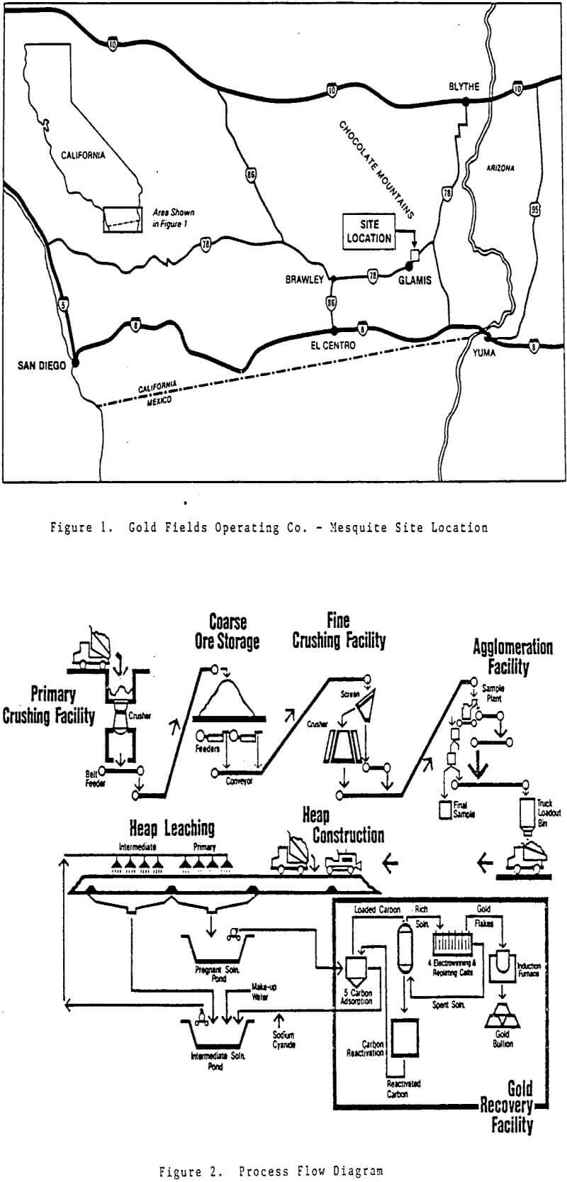
Gold Fields’ Mesquite mine, located in southeastern California, heap leaches low grade gold ore at an annual rate of 2.7 Mt (3 million st). Ore is crushed in a two stage open circuit and belt agglomerated prior to loading on the leach pads. Since initial heap construction in October of 1985, a number of operating practices have been modified and several agglomeration techniques have been tested in an effort to improve percolation and reduce leaching time. Findings to date are discussed.
Mineralization
The host rock for gold mineralization at Mesquite consists primarily of biotite gneiss and hornblende biotite gneiss, interspersed with layers of schistose material. Gold mineralization is controlled by a series of high angle faults that acted as channels for hydro-thermal fluids which provided precious metal values to the host rock or remobilized existing mineralization.
The combination of hydrothermal alteration and extensive faulting in the orebody has resulted in material that is extremely friable. Ore mined to date is characterized by a significant percentage of natural clay-like fines that tend to increase as ore grade increases. While the altered nature of the ore is critical for exposing gold values and yielding excellent leach recoveries, the resultant fines produced also hinder leaching by limiting solution percolation in the heaps.
Ore Processing
Run of mine ore is crushed in a 1.1 x 1.8 m (42 x 70 in) Nordberg gyratory crusher to -150 mm (6 in). The crushed ore is conveyed 890 m (2920 ft; across Highway 78 to a 109,000 tonne (120,000 st) stockpile that is topped by a large fabric covered dust cap. The stockpile provides approximately 13 600 tonnes (15,000 st) of live ore storage.
The ore stockpile feeds the secondary crushing circuit consisting of a 2.4 x 7.3 m (8 x 24 ft) Allis Chalmers vibrating double deck screen and a 2.1 m (7 ft) Symons shorthead cone crusher. Oversize from both screen decks reports to the cone crusher while the bottom deck undersize reports to the crusher product belt. Although the crushed ore top size can be as coarse as 102 mm (4 in), the crusher product is generally controlled at 90% -51 mm (2 in).
The agglomeration facility consists of two short conveyors with spray systems in the discharge chutes, and one longer conveyor that feeds the agglomerated ore to a truck load out bin. Ore entering agglomeration discharges from the secondary crusher product belt onto the first of the three conveyors. Barren solution pumped from the gold recovery plant is sprayed onto the ore immediately after it falls onto the belt.
The leach pads at Mesquite lie directly south of the crushing/agglomeration facilities. To date, three pads have been installed with plans for as many as 17 more over the life of the mine. Pads are constructed by grading and compacting the existing soils followed by placement of a 1.0 mm (40 mil) PVC (polyvinyl chloride) membrane on the compacted surface.
Leach Pads 1 and 2 were initially constructed and lined in 1985 prior to the startup of plant crushing facilities. The two pads are constructed as one large lined area with dimensions of 1280 x 230 m (4200 x 760 ft). A lined berm runs lengthwise between the two pads with Pad 1 sloping to the west of center, while Pad 2 slopes to the east. The entire pad slopes lengthwise towards the south at 1.25%, while the slope from, the center berm to the edge of either pad is 1.63%. A series of raised berms perpendicular to the centerline are spaced at 64 m (210 ft) intervals, separating each pad into 20 individual sections. Each section is equipped with V-notch weir gates at the edge adjacent to the collection ditches.
Solution pumped from the pregnant solution pond flows through five carbon columns in series, each containing 2.3 tonnes (2.5 st) of activated charcoal. The gold is adsorbed by the carbon particles as the solution flows through the tanks resulting in essentially complete gold recovery before exiting the final carbon column. This barren solution then flows to the intermediate pond where it is pumped to the ore heaps to continue the leaching cycle.
Leach Pad Performance
As of October, 1986, over 2.3 Mt (2.5 Mst) of ore had been placed on the leach pads and put under spray. This represents 38 leach pad sections from the first 4.6 m (15 ft/ lift of Pads 1 and 2, each containing 55,000 tonnes (60,000 st) of ore, and four sections from the second lift each averaging approximately 50,000 tonnes (55,000 st). By monitoring the performance and observing the problems with these individual sections, a number of modifications and improvements to heap leaching practices have evolved at Mesquite. Leach performance has improved substantially since spraying of the first sections began in late January of 1986.
Initial ore placement on the leach pads began in late October of 1985, three months prior to the first application of leach sprays. With the onset of leaching in late January of 1986, 330,000 tonnes (360,000 st) were already in place on Sections 1 through 3 on Pads 1 and 2.
Heap construction remained split between dozer float and truck dump methods through the first 8 sections on Pad 1 and 2 respectively. As more sections were put on line and began producing, evidence began to mount in favor of the truck dump method for yielding better leach performance. Average leach recovery curves on the truck dump side were significantly steeper during early stages of leaching, suggesting overall leach times could be minimized by eliminating dozer float as a method of heap construction.
Original design parameters called for solution application rates on the leach pads of 0.003 L/sec/m² (0.004 gal/min/ft²), equivalent to about 20 L/sec (320 gpm; on each pad section. Leach solution was applied initially with Senninger Wobblers equipped with 8 nozzles, equivalent to a 3.2 mm (1/8 in) orifice. Design solution application on the heaps quickly resulted in surface runoff and ponding in low areas, forcing a reduction in flow to the sprays.
Ore placed on the first six sections of Pads 1 and 2 was crushed to -32 mm (1¼ in) utilizing a secondary crusher closed side setting of 16 mm (5/8 in). Beginning with ore placement on Section 7, the closed side setting was opened to 51 mm (2 in), producing a cone crusher top size of -102 mm (4 in). Two factors prompted the decision to coarsen the ore particle size: 1) the disappointing and unpredictable performance of the first several sections, and 2) pilot test heap results that indicated -102 mm ore could be leached at improved percolation rates without compromising recovery.
Recovery Curves / Summary
Recoveries are calculated based on sampled head grades of ore to the pad, and from the daily gold production off the heap based on weir flows and solution assays. Comparisons to actual gold production indicate overall recovery figures are within five percent accuracy. For the composite curves, Section 6 was grouped with unagglomerated sections due to the interruptions in agglomeration experienced during the initial startup of sprays. In addition, the bulk of the gold leached from Section 6 reported to Section 5, making separation of those sections difficult.
The curves shown summarize the agglomeration and heap leaching practices which have evolved at Mesquite over the first nine months of leach operation. The unagglomerated sections represent the worst case in terms of leach performance with gradual and occasionally drastic improvements resulting from initial attempts at agglomeration with water and lime, heap leveling, coarser ore size, cement agglomeration, sprinkler modifications, and finally agglomeration with cyanide solution and pebble lime.


