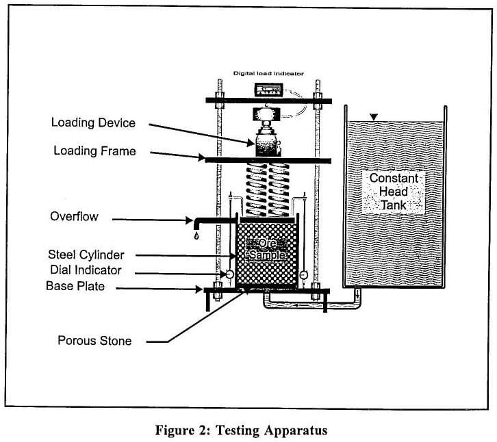
The test method developed to determine the permeability of ore under increased confining pressure was modified from the Bureau of Reclamation test standard, Designation E-14 (Bureau of Reclamation, 1974). The test apparatus consists of a 12 inch diameter steel cylinder, bottom porous stone, base plate with a drain, porous top plate, reaction frame, and a loading device. A sketch of the test apparatus is presented in Figure 2. An ore sample is first weighed out and then poured into the steel cylinder. The poured density is then recorded along with the initial moisture content. A constant head permeability test can then be performed, under no load, in general accordance with the test method. The axial load is then increased to a pressure which simulates a certain heap height. During the consolidation period the axial deformation of the specimen is measured using a dial gage until the change in specimen height is negligible. The permeability test is repeated under this load. This process is then repeated for several additional simulated heap height pressures. The head used during the test must be carefully controlled. If too high a head is used during the test, fines will be washed out of the sample and the test will not be valid. Once the specimen has been subjected to several load-permeability testing stages, the results can be plotted to show how the ore permeability varied during the test under increasing axial loading.

For the solution to one dimensional unconfined flow between parallel drains with vertical infiltration (McWhorter and Sunada, 1977), the equation takes the following form:
h² = QL²/4k……………………………………………………………………..(1)
where:
h = maximum head on the liner
Q = application rate
L = pipe spacing
k = permeability of the ore
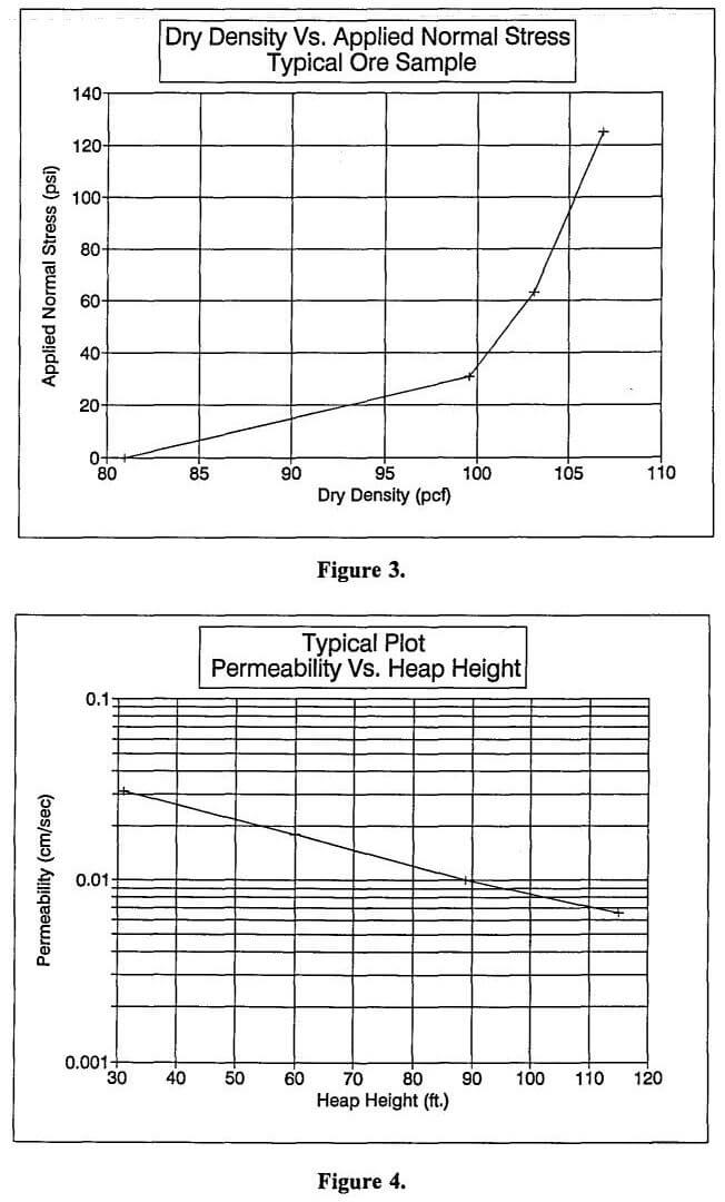
As the load is applied the ore particles re-arrange and break down to form a denser material than what was originally dumped into the mold. A typical plot of applied normal stress versus dry density is presented in Figure 3. As shown in Figure 3, the dry density for this sample increased by approximately 30% as the sample went from a no load situation to a simulated heap height of about 170 feet. The greatest change occurred during the loading from 0 to 30 pounds per square inch (psi).
As the ore densifies, all of the geotechnical properties of the ore are changing. The same ore under zero load will not behave the same as the ore under several lifts.
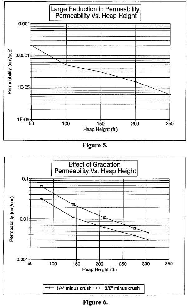
A graph of permeability versus simulated heap height for as typical gold ore is presented in Figure 4. For this sample, the permeability of the ore went from 0.03 cm/sec to 0.0065 cm/sec under a simulated heap height of approximately 115 feet. Based on the equation presented previously, for a pipe spacing of 50 feet and an application rate of 0.005 gallons per minute per square foot (gpm/ft²), the maximum head on the liner would have increased from about 2.7 feet to approximately 5.7 feet. While this may not have a catastrophic effect on stability, leakage losses through the liner will increase along with the time for solution recovery.


