The phenomenon of “surging” in a mill is a subject upon which very little has been written; presumably because it is a condition which cannot be tolerated in mill operation and which must be eliminated by variation of some or many of the physical dimensions or characteristics of the mill or mill charge. The phenomenon known as “surging” consists of a pendulum-like oscillation of the whole charge of the mill, within the mill shell. Thus for one part of the cyclical motion the charge is moving around the centre of the mill in the same direction as the mill shell, and during the second part of the motion, in the opposite direction. As a consequence of this oscillatory motion of the charge, the torque necessary to maintain the mill shell in steady motion fluctuates widely and, in certain circumstances, can make such demands upon the driving motor that the circuit breakers are thrown out. This throwing out of the circuit breakers is, however, a lesser evil since the danger is, in such a case, apparent and must be remedied. A more subtle danger is hidden in fluctuations of torque which are insufficient to bring the circuit protective devices into operation. In this case the existence of such fluctuations is not apparent, and the maintenance of fluctuations may lend to the destruction of the driving gearing through fatigue failure. Although, for obvious reasons, but little is made public concerning such failures, it is fairly well known that failure of the gearing of large mills is encountered with a frequency such as to suggest that factors other than mere wear and tear are operative.
The oscillatory motion of the charge, which has been described above, is complicated by the collapse of the leading toe of the charge when the charge comes to rest at the end of the forward motion. This collapse imposes fluctuations of small amplitude but higher frequency upon the fluctuations arising from the main motion; this, in turn, gives rise to a complex motion which involves a great number of harmonics in the frequency spectrum.
Consider now the motion of the charge in some detail and, since, in Chapter 2, it has been shown that the equilibrium surface of the charge approximates to a straight line, the charge may be considered to be a mass of the shape shown in Fig. 7.1. The following mathematical treatment, which has been suggested by Hinsley, is then applicable.
The charge in the mill is assumed to be a coherent mass with the centre of gravity at G. The gravitational force mg and the centripetal force mrω² have a resultant R which meets the shell at P. This resultant can, in turn, be resolved into tangential and normal components at P.
Then,
FR = mμR (rθ² cos ε+ g sin ψ )
~ mμR cos ε( rθ² + g sin θ ) ……………..(7.1)
since ε is small.
Also, from the equations of motion
or, mk²θ = mgr cos θ – FR
θ = gr/k² cos θ – FR/mk² ………………….(7.2)

Combining (7.1 ) and (7.2)
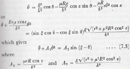
Let ∅=ξ-θ, so θ = -∅ and θ = -∅, so that
∅ -Α1∅² = -Α2 sin ∅ …………………….(7.4)
This equation can be integrated once by use of the integrating factor 2e-2Α1∅, whence

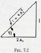
where η and 2Α1 are related as shown in Fig. (7.2).
If now the angle θ, at which the charge just slips, is observed by experiment and since, for this condition, ∅ = 0 the value of C1 the constant of integration, c, may be obtained from equation (7.5). Since equation (7.5) is a quadratic there are two solutions, ∅1 and ∅2, to the equation ∅² = 0 which, in practice, are one negative and the other positive.
The expression (7.5) is the equation for the velocity of motion of the charge and the solution can be taken no further by formal methods. For practical purposes, however, it is desirable to know the time for a complete oscillation, since the frequency of the oscillation may then be calculated thus.
The time, t, of the descent of the charge is given by

This equation may be solved by graphical and numerical integration.
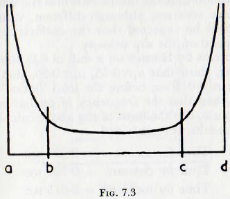
When the function on the right-hand side of equation (7.6) is plotted, a curve of the form shown in Fig. (7.3) is obtained. The portion of the curve between b and c may be integrated by Weddles’ rule, or any similar method, but owing to the infinite values, the strips above ab and cd cannot be so treated.
An inverse sine function is therefore fitted to these end strips so that

and by the correct choice of α, β, a and x a very close fit may be obtained. Thus the time of descent of the load may be computed.
After the load has gripped the shell, the ascent is made at the same speed as the shell. Thus the time of ascent is given by (∅1 – ∅2)/ω; where ω is the angular velocity of the mill shell.
By the above treatment the frequency of oscillation of the charge may be calculated, provided that certain information, which must be obtained by observation on the mill, is available. Furthermore, the treatment is based on the assumption that the coefficients of static and dynamite friction have constant, although different, values; but in fact it would be expected that the coefficient of friction would depend on the slip velocity.
Experiments by Hinsley on a mill of 6 ft diameter with 40% filling, show that μs~0.35, μd ∼ 0.25, that there is a lag of about 0.015 sec before the load “locks” on to the mill shell, and that the frequency of oscillation is about 58 per minute. On the basis of the above calculations the following results were obtained.
Time for ascent = 0.233 sec
Time for descent = 0.787 sec
Time for locking = 0.015 sec
Time for cycle = 1.035 sec
This gives a frequency of 1/1.035 x 60 = 58 c/min, which is in close agreement with the observed value.
The above treatment is of great interest in that it gives the frequency of surge with considerable accuracy, but it is not of such a nature as to decide, whilst the machine is still on the drawing board, the question of whether a mill of proposed design will surge or not.
In a theoretical study of the problem, one of the present writers, Rose, attempted to analyse the motion of the mill charge by use of the mathematical method of topology; variations of the coefficient of friction with rubbing velocity being included in this treatment. On the basis of the topological diagram relating to a mill of about 8 ft diameter, together with an assumed but probably reasonable relationship between the coefficient of friction and the rubbing speed, the curve relating the torque to rotate the mill shell at constant speed, on a base of time, was computed and this curve is shown in Fig. 7.4. From this curve it is seen that violent surges in the torque occur; a maximum of about 2.5 times the mean torque being attained at a frequency of about 30 c/min. This ratio of maximum
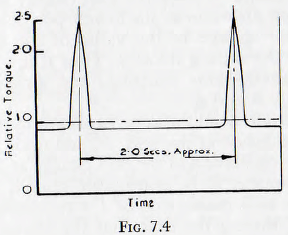
torque to mean torque is in fair accord with an observation by Hinsley, working on the mill mentioned previously, that during surging the current to the motor varied between about 300 and 700 amperes.
Having regard to the theoretical nature of the treatment of Rose, which involved a number of assumptions as to the values of important parameters, the agreement between the observed and calculated magnitude of the current surge is as close as can be expected. It appears reasonable to conclude that peak values of the torque of at least two or three times the mean value may be encountered during surging.
The topological method is, however, not of a nature such as to be readily used in the design office. In an effort to obtain a simple criterion for the existence, or non existence, of surging, an experimental investigation was carried out by one of the present authors with a co-worker, Rose and Blunt; use being made of the small-scale models and the test apparatus already illustrated in Fig. 3.1.
The basis of this work is that the angle 2α through which the centre of gravity of the mill charge oscillates is dependent on the “fluidity” of the charge and this quantity, for reasons already discussed, depends upon the mill diameter, D, the ball diameter, d, upon the coefficient of friction μ, of the mill charge (if μ = 0 the mill charge would always be in stable equilibrium at the lowest position of the mill) and upon the change of the value of the coefficient of friction with the sliding velocity. Thus if μv = μ0 (1 + ∅Bv), where ∅ denotes some function, the amplitude would depend on μ0, B and ∅.
The amplitude would also be expected to depend upon the speed of rotation of the mill, N, and upon the periodic time, t, of the oscillation of the mill charge as a pendulum This would appear to be reasonable since if N and t are such that the mill makes one or 1/n revolutions, where n is an integer, during the time that the charge makes one complete cycle, then any roughness of the mill, such as a filling hatch, would produce forces which are synchronized with the oscillation of the charge and the oscillations would build up. If, however, synchronization is not present, then oscillations would be unlikely to build up.
Finally, the amplitude would be expected to depend upon the mill filling, J, since both the restoring force acting on the mill charge and the frictional forces, which depend on the number of contact points, depend upon this quantity.
Thus
α = ∅(D, d, μ, t, Ν, Β, J) ……………………..(7.8)
where again ∅ denotes “some function of”.
If now the methods of dimensional analysis are applied to these variables it is found that
α = ∅{(D/d), (Nt), (μ), (J), (BDN)} …………………..(7.9)
The analysis may be carried further thus:
Let N be some fraction of the critical speed Nc of the mill so that N=kNc. Now it is easily shown that, for a given mill filling, the periodic time of oscillation of the ball charge varies directly as √D and also that the critical speed Nc varies as √(1/D) and so the value of (Nt) is imlcpcndent of the size of the mill, thus it follows that, as far as this group is concerned, the results of the model tests are directly applicable to the full-size mill.
Turning attention now to the group (BDN) it follows that, as before N ∝ √(1/D) so this group becomes (B√D). Thus, it follows that there is some “scale effect”, the value of this group increasing as the root of the mill diameter. But on the other hand, the value of B is usually small and so the variations in the value of the group would be expected to be small. Furthermore, the effects rising from the velocity dependence of the coefficient of friction can be, to some extent at least, absorbed by the use of the average between the coefficients of static and dynamic friction.
Thus, it would be expected that, in any practical mill, the effect of this group will not be large.
Thus, the basic equation for surging in a mill reduced to at least for a first approximation,
α = ∅{(D/d) , (μ), (J)} ……………….(7.10)
In accordance with this equation, tests were carried out to establish how the existence, or otherwise, of surging depends on the dimensionless quantities on the right-hand side of the equation.
It has already been shown, in Chapters 2 and 3, that the fluidity of the charge decreases with an increasing number of contact points and with increasing coefficient of friction. Thus, the mill filling, J, and the coefficient of friction, μ, are, as far as the fluidity of the charge is concerned, interchangeable, and it would be expected that these quantities would occur in the form of the product Jμ. Then, from analysis of the experimental results, it was found that a line could be drawn across the field of a graph, Fig. 7.5, on which (Jμ) is the ordinate and (D/d.) the abscissa, and according into which part of the field of the graph the operating points fell, either surging does or does not occur. Thus, in order to establish whether
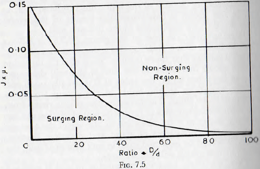
surging is likely to occur or not it is only necessary to establish the product of J, the proposed filling of the mill, and μ, the effective coefficient of friction of the ball charge and material undergoing milling, and to plot this value against the proposed value of the ratio D/d. If the operating point so obtained is well inside the “non-surging” zone then it is improbable that the mill will surge but if the point is inside the “surging” zone, or dangerously near the boundary line, then surging is likely to occur and the size of the balls or the magnitude of the mill filling, or both, should be varied in order to bring the operating point within the “non-surging” zone.
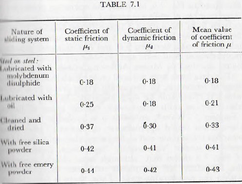
The foregoing treatment involves a knowledge of the mean of the static and dynamic coefficients of friction of the ball charge and material being processed, and hence of the static and dynamic coefficients individually. Examination of the literature does not reveal values of the coefficients of static and dynamic friction applicable to masses of balls loaded with various types of powder. However he authors have made rough determinations of these values under conditions which are likely to be applicable to ball mills; that is, balls and powder were placed in an open-bottomed box on a smooth steel surface and the tractive force necessary to move the box measured by means of a spring balance. This method is believed to give results of sufficient accuracy for the present purpose and a number of such results are shown, for purposes of illustration, in Table 7.1.
It might be of interest to note in passing that the dependence of surging upon the coefficient of friction, as revealed by model tests, is as shown in Table 7.2, and that
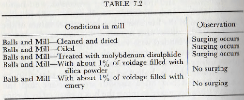
this observation is in accord with experience, since it is unusual, though not impossible, for surging to arise in mills grinding cement clinker, limestone or such similar materials which give rise to a high coefficient of friction. Confirmation of the general accuracy of this criterion is contained in Fig. 7.6, in which the operating points for a large number of mills are plotted; these points being calculated from the data of Taggart and relating to mills between about 4 ft and 10½ ft diameter. Additional data relating to mills between 2 ft and 8 ft diameter grinding molybdenum disulphide and graphite are included; these being supplied by Messrs. Acheson Colloids Ltd.
The data have been reduced on the basis that the coefficient of friction is, for the metalliferous ore, 0.4; a figure which is reasonable for such materials. In fact, the data also refer to mills fitted with various types of liners, “Shiplap”, “Wave”, etc., but it is probable that all of these liners would approximate to “smooth” after some wear has taken place and so, for safety, these mills should be operated under “non-surging” conditions. Examination of Fig. 7.6 shows that, although some closely approach the boundary, all the points, with one exception, fall within the non-surging zone. Thus, there is fair, though
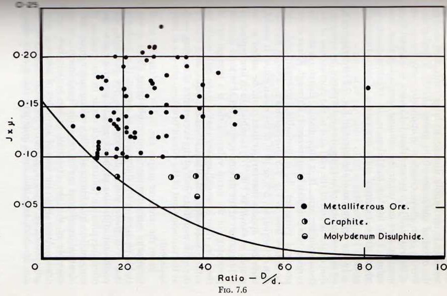
not absolutely conclusive, evidence that the results of the small-scale tests apply directly to large mills, and so that the effect of variations of the group (BDN) is negligible Strictly, the above criterion is applicable only for values of the ratio (N/Nc) greater than 0.15 since it is found that surging does not occur for running speeds less than this value. This further condition is, in practice however, trivial since industrial mills are rarely, if ever, operated at such low speeds.
In the derivation of the curve of Fig. 7.5, the existence , or non-existence, of surging was determined by observation of the sound of the mill and of the fluctuations of the dynamometer arm. It is improbable, therefore, that the surging was completely suppressed; although it was so for practical purposes. It is probable, however, that the boundary line on Fig. 7.5 corresponds to a small fluctuation of torque; say 5% or 10% of the mean value. It would, therefore, appear that further lines could be added to the graph, as shown in Fig. 7.7, in which each line represents a fluctuation in the driving torque, equal to some definite percentage of the mean value. If this is a true picture of the case, then it would appear that a given mill might be subject to considerable fluctuations of torque, even though the gross manifestations of the occurrence of surging, such as the throwing-out of the circuit breakers, are not at once apparent.
From the tentative graph, Fig. 7.7, it is clear that small changes of operating conditions could bring about appreciable changes in the fluctuation of torque. It is probable that it is these minor differences in, for example, the coefficient of friction of the charge, which give rise to the often inexplicable failures which occur in the gearing of some mills, whilst identical mills working under apparently identical conditions suffer no such breakdowns. As an example of this the attention of the writers has been drawn, Anon to the case of a number of identical tube mills, working under apparently identical conditions, in one of which mills the main gear pair failed after about 10,000 hours’ service; whereas the other mills have given completely satisfactory performance over a number of years. The reduction gearing of these mills, which were designed and constructed by makers experienced in the construction of gear trains such as those used in rolling mills and in ship turbine installations, were generously proportioned and apparently adequate for the heaviest duty. If now it is assumed that the fundamental fluctuation of torque is of the order of 30 c/min, which the tests of Hinsley and the calculations of Rose indicate as being probably reasonable, and that the reduction ratio of the slow speed pair is 5 to 1, then 10,000 hours of service would correspond to about 3,000,000 cycles of stress on the gearing. It is significant that it is at this order of numbers of stress cycles that fatigue failure would be expected to occur.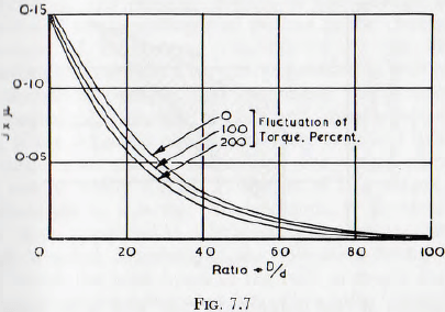
If, in the absence of an exact knowledge of the composition of the gear material and the heat treatment employed, it is assumed that the fatigue characteristics of the gear material are approximately the same as those for which the diagram Fig. 7.8, quoted by Morley, was derived, then this diagram may be used for the further analysis of the present problem. The diagram of Fig. 7.8 is such that, for an indefinite number of reversals before failure, the working stresses must fall within the shaded area.
Now suppose that the minimum stress, corresponding to the mean driving torque, is 20 tons/in². It follows that, if failure is not to occur within a limited number of applications of the stress, the maximum stress must not exceed about 25 tons/in²; that is, the allowable fluctuation of torque must not exceed about 25 % of the mean value. However, it has already been suggested by Fig. 7.7, that fluctuations of this magnitude may well arise from quite moderate changes in mill conditions, possibly by, say, 10% variation in the value of the coefficient of friction of the charge, and that such changes could well be brought about by differences in pulp density, particle size, surface finish of the balls and mill, etc., which are so small as to be normally regarded as unimportant. Thus, it would appear that the unexplained gear failures encountered in practice might arise from differences in the physical conditions of the mill liner, ball charge and powder characteristics. These are so small as to be regarded as unimportant but do in fact, have a profound effect on the torque fluctuations transmitted to the gearing. The problem is still further complicated by the fact that the stresses involved will depend upon such factors as the rigidity of the drive, the torque-speed characteristics of the motor, etc. Thus, for example, if the motor characteristics are such that the mill is allowed to lose speed as the torque increases, the load on the gearing will be lower than if the motor maintains the speed of rotation more or less constant. For these reasons exact calculations as to the torque fluctuations are impracticable, but there remains no reasonable doubt that a mill should be operated as far within the “non-surging” zone of Fig. 7.5 as is possible.
Grinding Mill Vibration Cause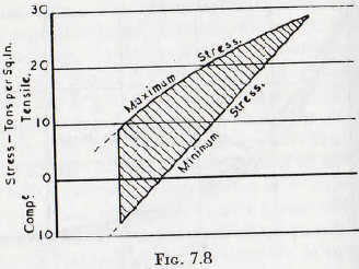
It has already been pointed out that, owing to the periodicity of any surging motion of the charge within the shell and to the collapse of the toe of the charge, the fluctuations of the torque transmitted by the driving mechanism will contain a very large number of harmonics. It is therefore, possible that resonance might occur at some frequency, between a mill and nearby apparatus which, if the adjacent equipment were sensitive to vibration, could give rise to difficulties, the origin of which might not be easily traced. Problems of this nature have been discussed in a recent article, Anon., in which it is
shown that appreciable vibration may be transmitted through a piled foundation; the vibration being transmitted down the piles beneath the mill, through the bedrock and then emerging through other piles beneath the neighboring equipment. This effect would not be expected to be so marked with friction piles, since there would then be no underlying rock to transmit the vibrations and the clay itself would introduce considerable dumping. Nevertheless, it would appear that the correct design of foundations from the viewpoint of the transmission of vibration, is essential.
In the same article, it is mentioned that some vibration emanated from the mill gearing and it was suggested that this condition could be alleviated by the use of fibre or spiral toothed driving pinions in the gear train. In view of the discussion in the earlier part of this chapter, however, it appears that attention to the conditions within the mill shell might be more effective than such modifications to the gear train itself. A further type of vibration which might well be mentioned is the vibration of the mill shell, as a beam, under the influence of the falling charge. Probably the greater part of this vibration is absorbed by damping in the metal of the shell, the joints between the liner plates, etc., and, in a ball or tube mill there appears to be no need to introduce any special measures for its suppression. In a rod mill, however, the individual rods give a more violent impact when they make contact with the liner or the toe of the charge. It appears to be common practice to insert billets of wood between the liners and shell of such mills in order to attenuate the shock and to introduce some damping.
The particularly destructive action of heavy rods falling, on the mill liners emphasizes, however, the importance of running rod mills at a speed such that the rods impinge on the toe of the charge and not upon the liners.
