Table of Contents
Regardless of subsequent treatment, it is considered best to recover free gold as early and as completely as possible in the flow of pulp. Gravity concentration in various forms is made use of for this purpose and amalgamation used for recovering the gold from the gravity concentrate.
Concentration is also extensively practised where a large part or all the gold or silver is intimately associated with base-metal sulphides, and the technical and economic considerations involved indicate that such a step in the flow sheet shows advantages over direct cyanidation. Flotation methods, with or without some gravity concentration, are usually employed for this purpose.
The concentration of gold and silver ores has two principal objects in view:
- The recovery of free gold.
- The collecting of gold or silver values which are associated with sulphide minerals into a relatively small product for subsequent treatment. The latter may involve (a) shipping to a smelter, (b) selective grinding for cyaniding in the mill circuit, (c) cyaniding in a separate circuit with or without roasting.
Recovery of Free Gold
Methods for the recovery of free and relatively coarse gold can be classified as:
A. Direct amalgamation, using
- Mercury added to mortar boxes or ball mills.
- Amalgamated copper plates.
- Tray-type amalgamators.
B. Gravity concentration, (followed by amalgamation) using
- Riffles or sluices.
- Hydraulic traps.
- Unit cells and hydraulic cones.
- Jigs.
- Corduroy blankets.
In the case of method A, the gold forms an amalgam, from which it is extracted by the following steps:
- amalgam collection,
- cleaning of amalgam,
- pressing or filtration,
- distillation or retorting,
- melting.
In the case of processes B, the concentrate must be amalgamated by special methods which usually include a combination of light grinding and contact with mercury in a grinding “pan” or amalgam barrel. Extraction of the gold then follows along the general lines of the steps outlined above. Because the details of these steps are generally known or can be found described in Taggart’s “Handbook of Mineral Dressing,” Sec. 14-10, and other textbooks, brief descriptions only of a few typical amalgamation plants are given in Chap. XI.
Metallurgical engineers are generally agreed that free gold should preferably be recovered as soon as it is released by grinding. There are several good reasons for this: Coarse gold tends readily to segregate in various undesirable parts of the milling circuit, where it is subject to possible loss or theft; it dissolves more slowly in cyanide and may require prohibitively long periods of agitation; the gold may exist in a highly refractory or “rusty” condition and fail to dissolve completely in cyanide solution; if allowed to accumulate in classifier beds, sumps, or launders, its recovery entails considerable work in cleaning up a large bulk of sands at regular intervals.
The methods used for recovering free gold are discussed more fully in the chapter on “Bullion Recovery.” Gravity methods include hydraulic traps and riffles, corduroys, and jigs.
Recover Gold in Sulphides
In the case of gold associated with heavy minerals such as sulphides of the metals, the methods usually employed include gravity concentration or flotation. To determine the most suitable treatment scheme in any particular instance requires weighing the advantages and disadvantages of a number of possible flow sheets. The problem is complicated by the fact that frequently both free gold and gold associated with sulphides occur together in the ore and also that cyanidation either before or after concentration may be a necessary step in the treatment scheme for optimum extraction.
While flotation offers the cheaper and more efficient method of concentrating sulphides, it requires supplementary gravity equipment for recovering coarse gold, if present. Where cyanidation is also used, it involves either two separate circuits (since cyanide is a depressant for sulphides) or special methods of reactivation, as at Lake Shore, following cyanidation.
Tabling, on the other hand, has the advantage that it can be incorporated into the cyanide circuit itself and, as used at Hollinger, for instance, accomplishes the double purpose of classifying and concentrating the sulphides, so that only the coarser and more refractory sulphides are removed from the circuit for separate finer regrind and cyanidation, while the finer sulphides are already sufficiently ground for direct cyanide treatment.
If, as in many plants today, a final tailing for discard can be made by flotation, there is no question but that this flow sheet, which may include jigs or other gravity equipment for recovering free gold, is the one to use. There are obviously many advantages to be gained in having a small bulk of concentrate to grind and cyanide compared with treating the whole tonnage of ore mined.
Recover Gold by Gravity
Riffle or Sluice
This somewhat primitive device which has been in use since earliest times still finds application as a gold saver for small prospect or placer mining operations and on gold dredges. The sluice is essentially an inclined trough or launder, the bottom of which is provided with transverse strips, or riffles, with variable spacing. There are endless variations of riffling. The mixture of sand and gravel is washed through by means of a stream of water, and the heavy minerals, “black sands” etc., along with free gold tend to collect in the spaces between the riffles, while the lighter and coarser material is displaced over the top of the riffles. Periodically the feed is deflected and the heavy concentrate dug out by hand to be cleaned up by any one of the various methods later described.
Hydraulic Gold Trap
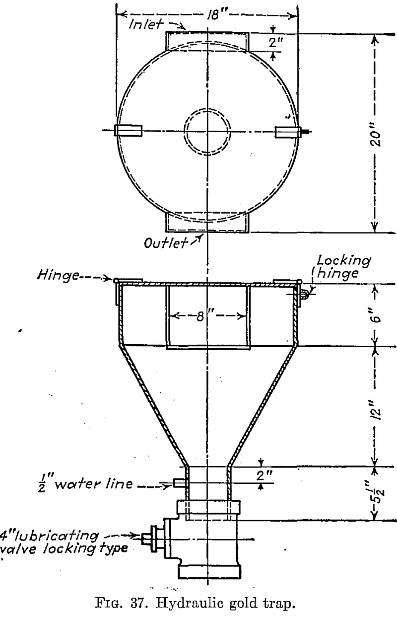
The hydraulic trap, another method of catching gold, is described by Ernest Gayford in Trans. 112, A.I.M.E., 1934, and is shown in Fig. 37. It is a simple device inserted in the mill-classifier circuit; sometimes two or more are used in series. At the Montezuma-Apex plant, Nashville, Calif., the 65-mesh discharge from each of two Marcy mills passed through five hydraulic traps, followed by corduroy tables, Dorr classifiers, and flotation. The traps were bled daily and thoroughly cleaned out twice a month. The product was concentrated periodically on a small Wilfley table. The concentrate was then ground and amalgamated in a barrel, and the tailing returned to the mill circuit.
Cones
At the cyanide plant of the Pickle Crow gold mine in northern Ontario three cones are built into the launder between the ball mill and classifier. Each cone is 18 in. in diameter with a slope of 60 deg. and fitted at the apex with a 4-in. nipple and discharge valve. A solution supply is connected into this nipple, and a regulated flow keeps the contents of the cone free of slime. The cones are dumped every 8 hr. under normal operating conditions, and the concentrate obtained varies from a few ounces to as high as 200 oz. of gold per ton.
The Unit Flotation Cell and Hydraulic Cone
To save coarse gold and recover free minerals at an early stage in milling, some plants installed the Denver Equipment Sub-A flotation cell and hydraulic cone. Figure 38 shows its place in the circuit at the Mclntyre-Porcupine mine, Ontario. The flotation machine and its use in the circuit have been patented in several countries.
The unit flotation cell prevents the accumulation of free gold in a ball- mill classifier circuit by removing coarse gold as soon as possible. Otherwise, because of its high specific gravity, the gold remains in this circuit until finely ground. Also, periodic surges of the classifier may allow this accumulation of gold to get into the mill circuit with resulting loss because coarse free gold is not readily floated and is often slowly extracted by cyanide. Moreover, the gold sufficiently fine to overflow the classifier lip is likely to become coated with sulphide slime during the grinding operation, reducing the recovery by flotation.
Jigs
During the last twenty years the use of a jig in the mill-classifier circuit to remove coarse gold has become a very general practice. In addition, jigs are widely used in placer operations to replace sluice treatment in the recovery of fine gold. Modern jig design has much improved the metallurgical and mechanical efficiency of these machines.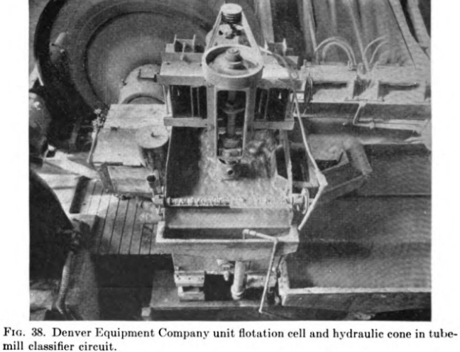
In the mill circuit, the jig offers the advantages of very small floor space requirements and very little loss of head. The mill jig installation is usually a compromise between gold recovery and available space limitations. Although it is depended upon primarily for the removal of only the relatively coarse values, a 60 to 70 per cent recovery of the total free gold values at the usual mill grind is not at all unusual. A good example of jig operation is to be found in the Preston East Dome practice, a complete description of which will be found in C.M.J., Vol. 62, page 535.
In placer treatment, the replacement of coco-matting-bottomed sluices by modem mechanical or placer-type jigs has resulted in marked improvement in recovery and lowered operating costs. The use of a hydraulically pulsated cleaner jig circuit in conjunction with continuous amalgamation has eliminated dredge shutdown time for cleanup and practically eliminated cleanup labor. Pilot sluices on jig tailings show almost complete saving of recoverable values by the jigs. Of interest is the comment of one South American operator that a proportion of the gold recovered by the jigs on his dredge is finer than can be recovered by native hand panners.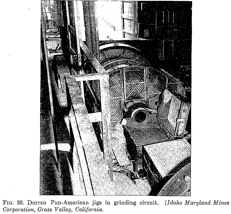
The high ratio of concentration (200-1000:1) made possible by proper jig adjustment enables the jig operator to strip off his values into a theft-proof, locked hutch or a screened and locked area in which a cleaner- amalgamation circuit can be operated.
Jig Capacity
The capacity of a jig is a function of the bed area. The ratio of length of bed to width is an important factor in determining the recovery into the concentrate. In placer work a length to width ratio of from 2-4:1 is used, being obtained by end flow grouping of a series of square cross-section cells. In mill circuit work space limitations usually restrict the length-width ratio to 1:1 or 2:1.
Dilution of the jig feed has a bearing on effective capacity; an adequate retention time through the machine must be obtained, and flooding with high-feed dilutions reduces overall capacity.
Mechanically pulsated types of jigs such as the Dorrco Pan-American, the Bendelari, and the Denver Mineral Jig have an average capacity of 2 to 2.5 tons per square foot of bed area per hour, expressed in terms of new feed. In mill circuits with high circulating loads the actual duty on the jig may be 10 tons per square foot per hour or more; it is noted that the correspondingly lower recovery of gold is accepted in such circuits.
Water requirements for mechanically pulsated jigs vary widely from as low as 2 to as high as 10 gallons per minute per square foot of jig bed area. These variations depend on the dilution of the feed, the particular design of the jig, the size distribution of the feed, the grade of concentrate desired, and the speed and the stroke of the jig. These last factors are interdependent with the volume of hutch water added; it is usual to establish the stroke and speed and then to use the volume of hutch water as an operating variable.

Mechanical Condition of the Jig
The average California practice for stroke and speed is shown in Table 17. The screen and shot sizes depend on the size of the concentrate desired. The size of the voids determines the effectiveness of sifting. A coarse bed (e.g., ¼-in. shot) recovers a coarse concentrate and has a larger capacity but may not exclude sand efficiently. A fine bed (e.g., 3/32-in. shot) recovers small grains effectively and produces a cleaner concentrate. The choice involves a knowledge of the size distribution of the ore minerals.
Using CORDUROY Sluice Mat GOLD SAVER
The use of blankets, canvas, coco matting, and corduroy—in fact, any material with nap—to save gold not held by copper plates, also to catch some heavy materials, has persisted from the time of Agricola to the present. From this practice has come the present use of corduroy alone to entrap the gold. It has replaced amalgamation on the Rand, is satisfactorily used in Australia and in Canada, and is slowly being introduced into the United States.
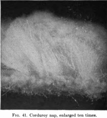
Corduroy is a thick and durable cotton stuff or cloth, corded or ribbed— a pile or nap on a base. Corduroy for wearing apparel differs from that used in gold recovery in having narrower and closer cords or ribs. Also, in industrial corduroy, the nap has been cut as in the pile on certain high- grade floor rugs, thereby offering innumerable spaces for entrapping gold.
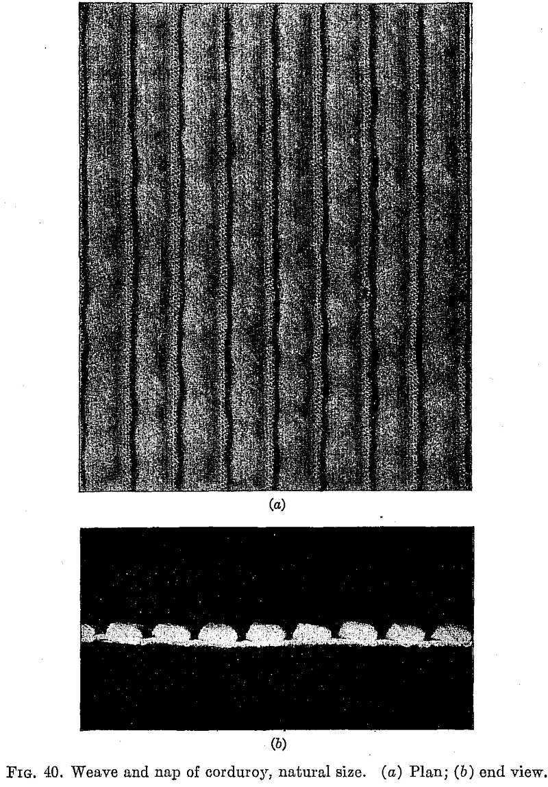
The material is known as a “pulp-sifting corduroy cloth.” It is woven from special material, and after being put through a serrating machine, it has a deep pile or nap with strong backing. Then the cloth is shrunk. It is made up into bales of about 80 yd. in two widths—28 and 36 in. Figures 40a and 40b show the weave and nap of corduroy.
Compared with the use of copper amalgamation plates, which they have almost completely replaced, corduroys show advantages in regard to lower initial cost, less skill required to operate and maintain, no danger from mercurial poisoning, less possibility of theft of amalgam, smaller loss of time, fewer effects of bad water and scouring by coarse pulp, and necessary general supervision. Corduroy is not expensive, it does not require skilled labor, theft is not so simple, and a remarkably large flow of pulp can be passed over it. Even if an ore is ground fine, it may pay to use corduroy in the flow sheet and catch the larger particles of gold which might prolong cyanidation.
What is known as “rusty” gold is amalgamable with difficulty, if at all. The metal may be coated with iron, occasionally with manganese or other elements. Copper plates will not catch this sort of gold, but corduroy will.
CONCENTRATION
Method of Applying Corduroy on Sluice
In laying corduroy, the,cords or ribs are placed across the table and flow of pulp, with the high side of the nap facing the stream. Each length overlaps the succeeding length a few inches.
In general, the slope of the corduroy table must be determined by actual trial-the size and specific gravity of the solids and the liquid-solid ratio being the principal factors that influence the slope. An unclassified pulp with up to 20-mesh sand at 4 or 5 to 1 dilution will flow down 1¾ in. per ft.; more dilute and finer pulp needs less slope. Roughly, 3 tons of ore passing over the tables should have 1 sq. ft. of corduroy.
Cloths are rinsed as often as may be necessary to keep the riffles from packing with heavy minerals. They are kept in use until the pile or backing gives way.
The final handling of worn-out corduroy is to burn it and treat the ash separately. It should not be fed to the mill circuit for fear that the carbon may precipitate the gold from the cyanide solutions. At the Dome mill the corduroy is dumped loosely into a tank in which cyanide solution is circulated for several days. This dissolves any fine gold enmeshed in the fabric. Then the cloths are discarded.
