Table of Contents
- Why Roast?
- CRUSHING
- Crushing
- ROCK PICK
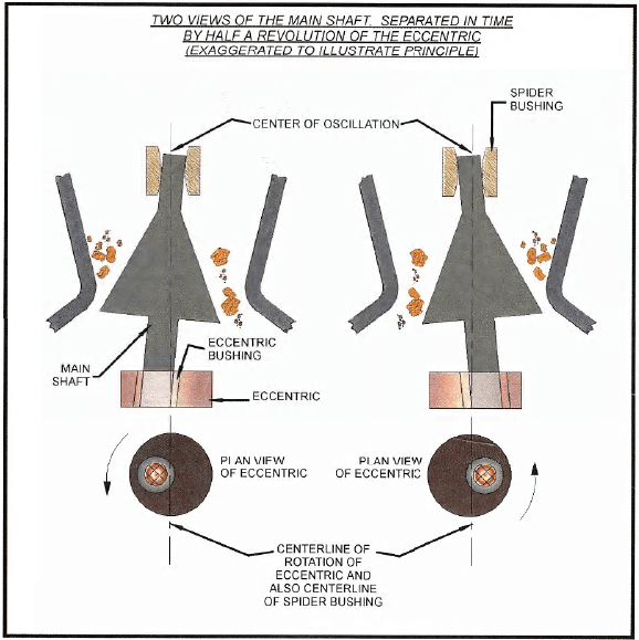
- GYRATORY CRUSHER
- CRUSHING ACTION OF A GYRATORY CRUSHER
- APRON FEEDER
- DOUBLE-DECK VIBRATING SCREEN
- CONE CRUSHER
- BAGHOUSE
- Dry Grinding for Roasting
- ROASTING
- Roaster Feed
- Roaster Operation
- ROASTER
- FLUIDIZATION CURVE
- Mist Eliminator and Booster Fan
- Wet Electrostatic Precipitator
- Mercury Removal
- SO2 Scrubbing
- Mist Eliminator and Exhaust Fan
- VENTURI SCRUBBER
- SHELL-AND-TUBE HEAT EXCHANGER
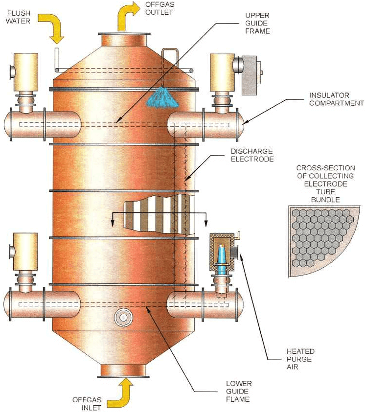
- WET ELECTROSTATIC PRECIPITATOR
- Mercury Scrubber
- CIL & NEUTRALIZATION
- Roaster Flow Sheet – Neutralization and C.I.L.
- TYPICAL VERTICAL LIME SLAKING MILL
- PRINCIPLE OF OPERATION TYPICAL VERTICAL LIME SLAKING MILL
- HIGH-CAPACITY THICKENER
- VERTICAL TURBINE PUMP
- INDUCED DRAFT CROSS FLOW COOLING TOWER
- GOLD LEACHING
- DERRICK VIBRATING SCREEN
- CIL Tanks
- The goals of the roasting process
To achieve optimum gold recovery from the certain sulfide ore body, the ore must be finely ground to achieve proper oxidation and mineral separation. The ore is separated into stockpiles after it has been mined. These stockpiles are based on gold content, sulfide content, and carbonate content. The ore is blended prior to being fed into the crushing circuit. The ore passes through crushing and grinding circuits to the Roaster circuit then to the Carbon and Leach circuit at a designed rate of 12,000 tpd. (13,000 /2002)
Crushing starts with the primary 42” x 65” gyratory crusher and fed to the Nordberg MP800 secondary crusher where it is crushed to 80% passing 3/4 inches. After the material is crushed it is stockpiled for feed into either grinding train. The material is ground from 1½ inches to 80% passing 200 mesh (74 micron) in a double rotator-grinding mill, run by a 10,000 hp motor. Material is split with a static classifier and a dynamic classifier with the underflow reporting back to the mill and the overflow going to the Roaster circuit.
The Roaster is also a duel train with 2 – 22’ diameter x 80’ high, two-stage stationary bed Dorr Oliver Roasters.
The gold ore is double-refractory. First, the gold is locked in sulfide mineral particles that must be oxidized to expose the gold for leaching. Second, the ore also contains preg-robbing carbon that will collect solubilized gold from the subsequent leaching circuit if the gold is not first removed. Both problems are addressed by roasting the finely ground ore in two roasters to produce a calcine with very low sulfur and carbon contents that is amenable to gold recovery in a conventional CIL (carbon and Leach) plant.
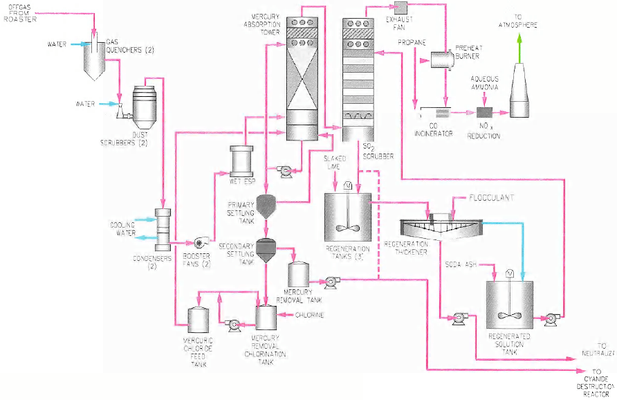
Offgas created from roasting is cleaned with a series of scrubbers and Mercury is separated and collected in tanks. Clean air is sent to the atmosphere. The roasted ore is sent to the neutralization tanks and then on to the CIL circuit.
The CIL circuit consists of 6 tanks, ranging from 50’ high to 60’ high with a 24” drop between tanks. The purpose of the CIL is to dissolve gold contained in the neutralized ore slurry by sodium cyanide leaching, and to adsorb the dissolved gold on to the surface of activated carbon.
From the splitter box, slurry flows to the C.I.L. tanks sized to provide a total of 16 hours of retention time. Each C.I.L. tank has an agitator and two Kemix wedge wire self-cleaning screens for carbon retention. Slurry discharging from the last C.I.L. tank passes vibrating carbon safety screens and is then treated with Ammonium Bisulfite (A.B.S.) for cyanide destruction. Detoxified tailings are pumped to the tailings pond. Reclaimed water from the settled tailings is pumped back to the process for reuse.
Carbon is advanced through the C.I.L. tanks on a shift basis. Loaded carbon (carbon loaded with gold up to 175 o.p.t.) from the first C.I.L. tank is sent to the existing carbon treatment plant for gold removal, electrowinning, refining, and carbon regeneration.
Why Roast?
Some gold ore at the Roaster is double refractory. First, the gold is locked in sulfide mineral particles that must be oxidized to expose the gold for cyanide leaching (Autoclaves do this function effectively). Second, the ore also contains preg- robbing carbon that will collect solubilized gold in the leaching circuit if it is not removed (oxidized) first. Both of these problems are solved by roasting the ore at high temperature.
CRUSHING
- Reserves 50 million tons at. 17 troy ounce per ton (cut off is .065 opt)
- ROM (run of mine) gold ore is delivered in large haul trucks (190- and 300- ton capacity) to a series of stockpiles where it is segregated based on ore grade, fuel value, and carbonate content. A loader reclaims ore from the different stockpiles and loads it into smaller haul trucks (85-ton capacity) to create a uniform blend. The blended ore is crushed in an open circuit – two-stage crushing plant (primary and secondary crushing) to produce coarse ore (80% passing ¾ inches and 97% passing 2 inches) to feed the dry grinding plant.
- Blending is critical for smooth operation of the plant.
PRIMARY
- 42 x 65 gyratory (500 hp)
- 120 ton dump pocket
- Oversize rocks broken with a rock breaker (50 hp)
- Crushed product is withdrawn from the surge pocket (rock-box) by an apron feeder (live operating Capacity of 60 to 100 tons)
- 1000 dstph feed rate
- 8″ OSS, 6” CSS
- Crushed ore is 98% passing 8 inches – 80% passing 6 inches
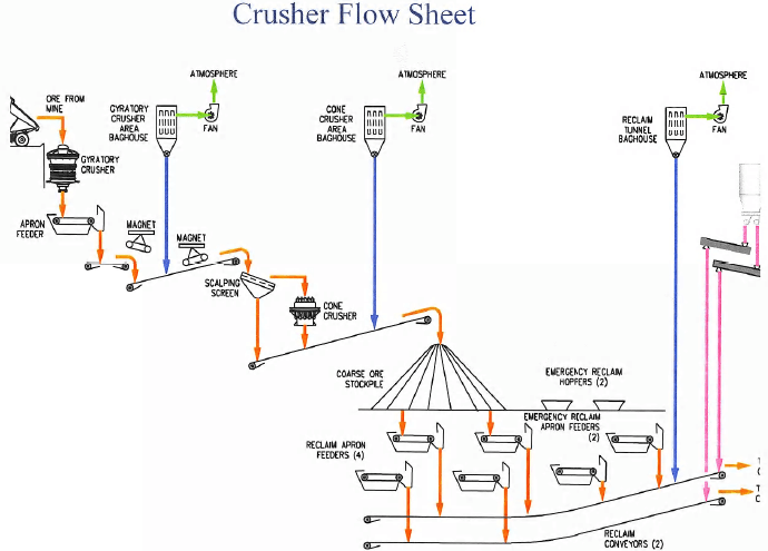
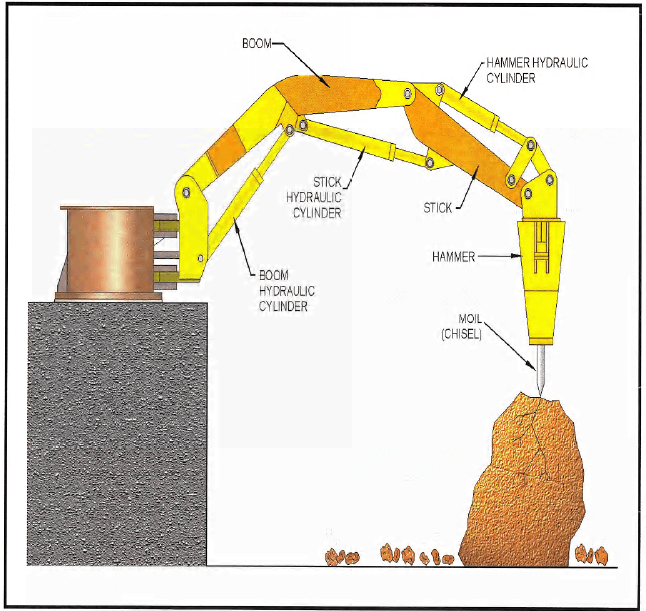
Coarse run of mine ore is supplied to the gyratory crusher by 85-ton haul trucks. These trucks unload the gold ore into the 120-ton capacity dump hopper above the gyratory crusher. A hydraulic rock breaker (rock-pick) breaks oversize ore within the dump pocket. Crushed product is withdrawn from the surge pocket (rock-box) below the gyratory crusher by an apron feeder discharging onto the gyratory product conveyor (501). The surge pocket variable live operating capacity ranges between 60 and 100 tons. The gyratory crusher product conveyor discharges onto the cone crusher feed conveyor (502). Primary crushed ore should be 98% passing 8 inches and 80% passing 6 inches.
Tramp metal is removed from the crushed ore using two magnets. The first magnet is located above the transfer point. The second magnet is located above the cone crusher feed conveyor immediately downstream of the baghouse dust recycle transfer point.
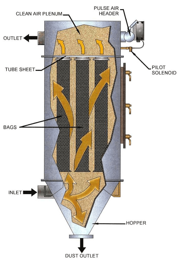
Dust from the primary crushing circuit is collected in the primary crushing bag house. Clean air discharged from the bag house is emitted to the atmosphere through the primary crushing baghouse stack. Collected material is returned to the cone crusher feed conveyor ahead of the second magnet for transfer to the secondary crusher system.
SECONDARY
- Single Nordberg mp800 crusher
Crush up to 1,000 tons hour
Closed side setting is ¾ inch - Double deck screen
3.0” x 4.0” screen on top deck
¾” x ¾” screen on bottom deck
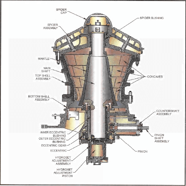
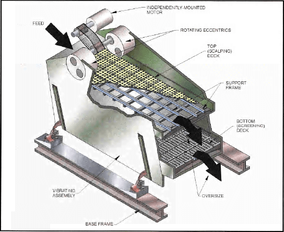
Ore discharge from the primary crusher circuit is fed to the double deck vibrating scalping screen of the secondary crusher circuit. Screen oversize (plus ¾ inch) is discharged to the cone crusher for secondary crushing. Conveyor transfers screen undersize and cone crusher discharge to the coarse ore stockpile.
- The secondary crushing baghouse collects dust in the secondary circuit. Clean air is discharged to the atmosphere and the collected material after it passes through the baghouse and the rotary airlock is directed to the stockpile-stacking conveyor (#503 belt) (83’ above grade).
- Ore Storage
• 8,000 ton live capacity stockpile
• 14 hrs feed for grinding
• 2 bunkers under the stockpile (reclaim tunnels), contain 4 apron feeders and 2 reclaim conveyors
• Ore is transferred from the stockpile by gravity to the apron feeders through 4 discharge hoppers located at the base of the ore stockpile.
• Two emergency reclaim feeders are located under two emergency hoppers. These are used when the stockpile apron feeders are not available. A front-end loader feeds ore to the emergency feeder hoppers.
• Inside the tunnels, dust is collected from the apron feeders and the reclaim conveyors by a baghouse. Clean air is discharged to the atmosphere and collected material is returned to the mill #2 reclaim conveyor (if the line is down it goes to a tote bin).
• A mobile vacuum truck collects spills of crushed ore in the primary and secondary areas and the tunnels. The collected ore is discharged to the stockpile.
Crushing
Primary Crushing-
Single Svedala 42 x 65 gyratory Crusher with a 100 ton dump hopper and a 150-ton surge pocket.
Hydraulic rock-breaker
Secondary Crushing-
8′ X 24′ double deck screen to pass 3/4″ product
Nordberg MP 800 standard cone set 3/4″ CSS
Reclaim-
Two 36″ conveyors each with two 4′ x 8′ Apron feeders and one 4′ X 8′ emergency
8,000 tons live capacity
PROCESS
ROCK PICK
GYRATORY CRUSHER
CRUSHING ACTION OF A GYRATORY CRUSHER
APRON FEEDER

DOUBLE-DECK VIBRATING SCREEN
CONE CRUSHER

BAGHOUSE
Dry Grinding for Roasting
ROASTING
The purpose of the roasting plant is to reduce the sulfur and organic content of the ore to increase gold recovery in downstream processes!
Roasting technology is based on two stage oxygen roasting as developed by Freeport Research
(2 trains) 2,000 dst silo (per roaster) 22’ diameter X 80′ high brick lined (170,000 bricks total)
2 Stages per roaster:
First Stage
1,025°F bed temperature
2 primary cyclones
2 secondary cyclones
Second Stage
1,050°F bed temperature
2 primary cyclones
2 secondary cyclones
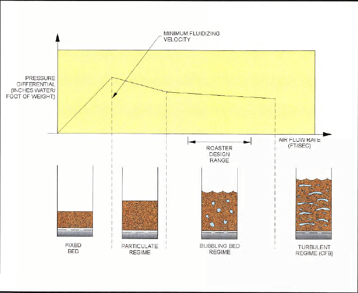
In its simplest form, a fluidized bed is a suspension of material in a gas stream, which behaves like a liquid. Fluidized bed roasting was selected because it efficiently destroys the sulfide minerals and organic carbon components of the ore while maintaining excellent control of the process temperatures. Temperature control in the roaster is critical because there is a substantial decrease in gold extraction at temperatures above 1050°F, and also coal combustion becomes unstable at temperatures below 1000 °F. Pure oxygen was selected as the combustion gas because it: 1) promotes rapid combustion at minimum temperatures; 2) reduces the amount of roaster exhaust gas minimizing the size and cost of the gas scrubbing equipment; and 3) allows the roaster to process a higher tonnage per unit area. The two stage design is preferred because; 1) the single stage design results in significant levels of unoxidized carbon exiting the roaster, reducing gold recoveries and 2) the two stage design allows the most efficient utilization of oxygen. The roaster is operated with the gas flow countercurrent to the solids flow. The countercurrent technique maintains the maximum combustion efficiency throughout the roaster by contacting the highest oxygen concentration with the lowest solid fuel content at any point in the roaster.
Roaster Feed
The roaster feed ore is 80% passing 74 microns. It is estimated that 10 to 25% of the ground ore will be smaller than 10 microns with the actual amount depending on the extent of the particle agglomeration.
Ground ore is discharged from the grinding mill product recovery baghouse and collected in the roaster feed silos. One silo is provided for each dry grinding circuit. Each silo has a 2,000-ton live capacity providing a normal 6 hours of roaster feed. The silo is designed as a mass-flow silo. The hopper section of the silo is sufficiently steep and has a coefficient of friction that is sufficiently low to ensure that all the material is discharged. This design ensures that there are no dead areas in the silo, i.e. areas in which the ore is stagnant and won’t discharge, and provides a first-in first-out operation.
Each silo discharges from a fluidized hopper at its base through a shutoff side gate capable of sealing against fluidized material, two control valves in parallel to provide volumetric flow control and an air slide to a common roaster feed distribution feed box. The fluidizing hopper design aerates the ore and helps to provide the required design discharge rate of 559 tons per hour per silo: each silo discharge can provide the full flow to both roasters.
The common roaster feed distribution box is fluidized with air. It discharges feed material to each of the two roasters feed systems. Each system includes a control valve, an air slide, a deaerator, and a feed weigh belt with drag conveyor, which discharges to the roaster feed bucket elevator. If required, a screw feeder adds coal to the weigh feed belt. From the bucket elevator, the ore is transferred to the roaster-fluidized feeder via an air slide.
Roaster Operation
Two parallel roaster circuits are provided to heat the refractory gold ore and oxidize the contained organic carbon and sulfide sulfur. Each roaster is comprised of two bubbling, fluidized-bed reactors in a single vessel, plus a fluidized feed system, first and second stage cyclone systems, and ancillary systems. The description below refers to one of the two parallel circuits.
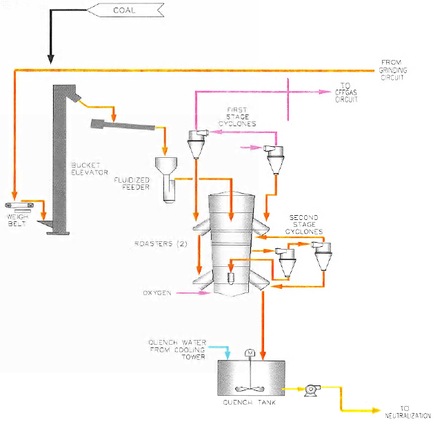
The fluidized feeder distributes ore continuously from its hopper to the first-stage (upper) bed of the roaster. The feeder is fluidized with air and overflows into the roaster through standpipes extending into the first-stage bed.
The upper bed is maintained at a constant, uniform temperature of about 1,025°F. The heat source for the first stage is provided by the ores net heat of reaction. Coal may be added to the ground ore to provide additional heating for low fuel-value ores, or fresh water may injected to cool the first stage bed for high fuel-value ores. Water may also be sprayed into the first stage freeboard to cool the roaster off-gas if excessive freeboard combustion occurs. The ore is oxidized predominantly in the first-stage.
Solids discharge continuously from the first-stage through the inner-stage solids transfer system to the second-stage (lower) bed, which is maintained at a constant, uniform temperature of 1,050°F. Diesel oil, pumped through oil guns, is used for heating, as required. The oxidation of ores is essentially completed in the second stage.
Low pressure, high-purity oxygen is introduced as the fluidizing medium through the cold windbox to the second-stage bed and to the solids transfer boxes. Hot exhaust gas from the second-stage reactor is conveyed through the inter-stage gas transfer system and the hot windbox to fluidize the first-stage bed. The hot, oxygen-rich gas from the second stage promotes rapid oxidation of the organic carbon, sulfur, and fuel in the first stage bed. The first-stage exhaust gas is de-dusted in the gas discharge system before passing to the gas quench and cleaning train.
Medium-pressure, high purity oxygen is injected through aspirators into the second stage hot windbox to purge solids. These solids may enter the hot windbox with the inner-stage gas or by sifting through the first-stage gas distributor.
Air is injected at various locations to fluidize the feed system, to provide transport medium for diesel oil, to cool oil and water guns, and to purge solids from instruments and other equipment.
The exhaust gas from each roaster stage is de-dusted in a set of primary and secondary cyclones. In both stages, the coarser fraction of the elutriated solids recovered by the primary cyclone is returned to the bed. The finer fraction recovered by the secondary cyclone is fed forward through the reactors, first stage to second stage and second stage to calcine product, to reduce accumulation of fines within the fluid bed.
Dust is carried over the first stage cyclone separators in the roaster off-gas (about 3% to 4.5% of the dry ore feed depending on the off-gas rate).
Dust collected within the roaster area is recovered in the roaster dust collection baghouse and returned to the roaster feed distribution box. Cleaned air is emitted to the atmosphere through the roaster baghouse stack. A critical relationship exists between roasting temperature, residence times, and the subsequent amenability of the ore to cyanide leaching. Precise control of these parameters is therefore essential.
Roasting One of Two Trains
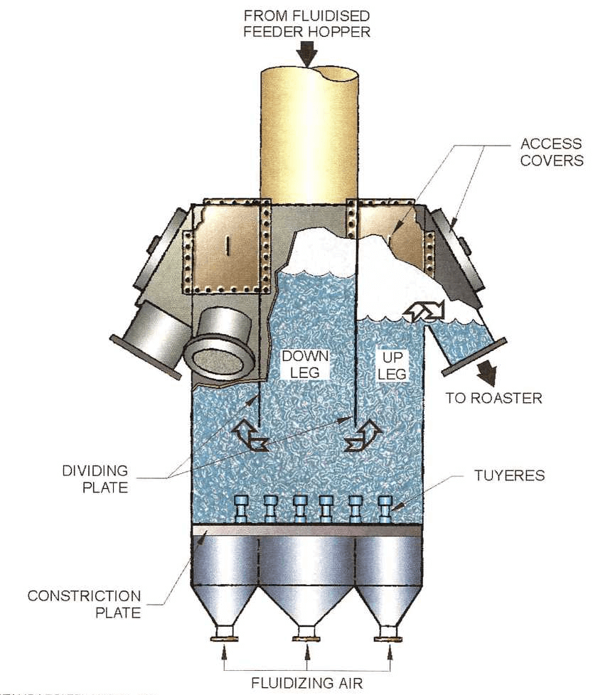
ROASTER
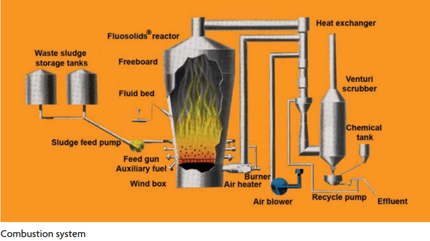
FEED FLUOSEAL DISTRIBUTOR
Roaster Design Basis
Sulfide Sulfur……………………………..1.9%
Total Carbon Matter……………………1.4%
Carbonate……………………………………4%
Fuel Value………………………………….300BTU
Mill Product P8o…………………………..74
First Stage Bed Temp…………………….1025 F
Second Stage Bed Temp…………………1050 F
Retention Time…………………………….44 minutes
Superfical Bed Velocity…………………0.7 to 1.0 ft/s
Superfical Freeboard Velocity……………1.5ft/s
Temperature Control……………………….Water or Coal
Oxygen Consumption………………………….10% of feed capacity
Recovery………………………………………………90%
REFRACTORY ORE FUEL VALUE (FV) CALCULATION MATRIX
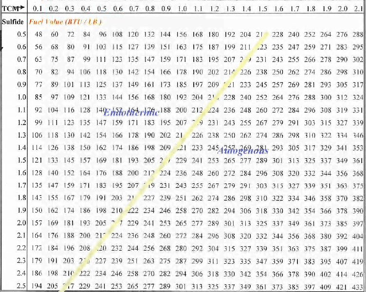 The developmental roaster stockpiles and their characteristics are summarized in Table 4.2.
A loader reclaims ore from the different stockpiles and loads it in 85-ton trucks to create a relatively uniform blend. The characteristics of the blend may vary from time to time but the normal targets are as follows:
- Head grade close to the overall average of 0.167 OPT.
- FV close to 287 BTU/lb to be well above 220 BTU/lb, the theoretical level at which the roaster reactions are autogenous (self-sustaining) and no coal needs to be added to the roaster feed. The operators use the matrix in Table 4.1 as a guide in selecting the ore from the different stockpiles to create the blend. (In Table 4.1. the term endothermic is used to describe the FV to the left of the sloping line. Endothermic means additional fuel is required to allow the roasting reactions to proceed.)
Carbonate content close to 5.5 percent CO3, or as high as possible consistent with the other two variables.
FLUIDIZATION CURVE
Off Gas Cleaning
A dedicated gas quench and cooling system is provide for the off-gas for each of the two roasters followed by a common gas scrubbing system. The off-gas is first quenched with water and a wet scrubber removes the dust. The wet gas condenser then cools the off-gas stream, removing water vapor in preparation for the booster fan, wet electrostatic precipitator (ESP) and mercury scrubber. Both mercury and SO2 are removed in the regenerative scrubbers. The gas stream is then conveyed by the exhaust fan for further treatment by thermal oxidation of CO and catalytic reduction of NO5. The cleaned gas is then emitted to the atmosphere through the gas-scrubbing stack.
Gas Quenching
2 Lines
The off-gas leaves the roaster freeboard at a slightly negative pressure (minus 1-inch water gauge) and passes through primary and secondary roaster cyclones. A damper on the emergency vent stack before the off-gas train acts as a pressure relief for the roaster.
By evaporative cooling, the gas quencher reduces the temperature of the roaster off-gas and saturates the gas with water, resulting in higher efficiency dust scrubbing in the next step. The co-current spray of water into the gas flow also serves to remove the coarse fraction of the dust. The dust scrubber then decreases the amount of dust to a suitable level for the condenser and wet ESP inlet and further cools the gas stream. The water used at the quencher and scrubber is a combination of condensate from the downstream wet gas condenser, cooling tower blowdown and fresh water.
The roaster off-gas enters the quencher at 1,024°F (979°F including an allowance of 1,500 standard cubic feet per minute for infiltration air). A co-current spray of 300 gallons per minute of water saturates the gas and cools the stream to 180°F. The quencher also serves to remove 50% of the dust, resulting in an underflow density of 6% w/w solids. The spray flowrate was chosen to achieve a reasonable underflow slurry density, while minimizing water consumption.
Dust Scrubber
2 Lines
99.7% particulate removal efficiency
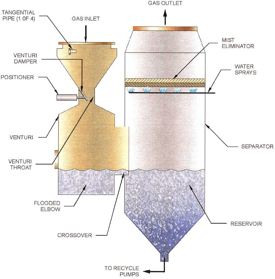
The quenched gas stream then enters the dust scrubber. This is a venturi- type scrubber that cools the gas stream to 171 °F while reducing the dust concentration to the required level. The dust scrubber pressure drop is 40 inches water gauge. The water addition rate to the scrubber is 680 gallons per minute of which 64% is recycled. An additional 30 gallons per minute is added to the dust scrubber mist eliminator. The dust scrubber underflow bleed flowrate is 300 gallons per minute for the base case and 450 gallons per minute for the design case when there is a higher solid loading in the roaster off-gas. The bleed flowrate was calculated to achieve a maximum underflow slurry density of 6% w/w solids. The use of underflow recycle minimizes fresh water consumption.
The underflow slurries exiting the quencher and dust scrubber are combined in the dust scrubber seal tank before being discharged to the roaster quench tank.
An emergency water tank provides gas cooling to protect process equipment from high temperatures during upset conditions, primarily power failures. Reclaim water is used to fill this tank when necessary.
Wet Gas Condenser
2 Lines 171 °F inlet temp. – 94 °F outlet temp.
2,180 GPM cooling water flowrate (per line)
13.7 lb/hr mercury condensed (per line)
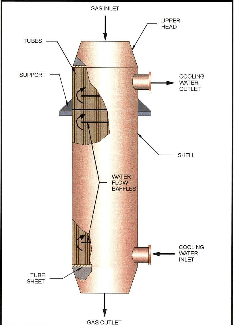
The wet gas condenser is a shell and tube heat exchanger. Gas is in the tubes and cooling water is in the shell (counter-current flow), which is used to cool the off-gas to 94° F. This temperature is controlled to achieve the maximum recommended mercury outlet temperature of 104°F. Gas subcooling (below 104°F) is required by the condenser to account for the heat of compression added by the booster fan. This temperature satisfies the mercury scrubber performance specification and pre-cooling prevents water condensation in the mercury tower, which would result in a high chloride bleed stream. Cooling is also beneficial at this stage because it reduces the volume of the gas stream and hence the required size of downstream equipment, recovers water in the form of condensate that can be reused in the process and condenses the majority of the mercury from the gas stream. Fresh water is providing on an intermittent basis for washing the condenser tubes.
The condensate flows by gravity to the inner section of the condensate collection tank. This tank is designed to allow efficient separation of mercury by gravity settling. A weir divides the tank into an inner section and an outer section. Condensed mercury settles to the conical bottom of the inner section, from which it is drained by gravity to the mercury collection tank in the mercury recovery area. Condensate overflows to the outer section of the tank, where it is combined with blowdown from the gas scrubbing cooling tower, blowdown from the oxygen plant cooling tower and fresh water make-up. Water is pumped separately from the outer section of the tank to the gas quencher and the dust scrubber.
Cooling water at 70°F is provided by the gas scrubbing cooling tower to reject the heat recovered in the condenser. The condenser is designed for a cooling water temperature increase of 40 °F.
Mist Eliminator and Booster Fan
A mist eliminator removes entrained water droplets from the cooled gas prior to the booster fan. The gas pressure is raised to minus 1-inch water gauge by the booster fan. This keeps the wet electrostatic precipitator under slightly negative pressure, minimizing the amount of infiltration air drawn into the system. Gas sub-cooling (below 104°F) is required by the condenser to account for the heat of compression added by the booster fan.
The two booster fans (one per roaster) (600HP General Electric motor) discharge to a common duct, producing a single gas stream of about 20,000 standard cubic feet per minute for further gas cleaning.
Wet Electrostatic Precipitator
The gas is saturated by fresh water sprays prior to the wet electrostatic precipitator (ESP), which removes particulate solids and liquid droplets entrained in the gas.
The wet ESP was specified for an inlet particulate loading of 0.45 grains per standard cubic foot design case. The design outlet particulate loading is 0.002 grains per cubic foot (5 milligrams per normal cubic meter).
The wet ESP was specified for an inlet acid mist of 0.50 grains per standard cubic foot base case and 1.17 grains per standard cubic foot design case. The design outlet acid mist loading is 0.0083 grains per standard cubic foot (20 milligrams per normal cubic meter)
Mercury Removal
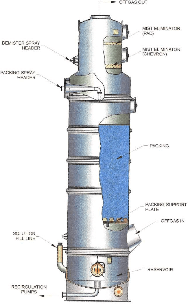
As a minimum control requirement, mercury emissions from the roaster must be limited to less than 10 tons per year. The mercury scrubber reduces the level of Hg in the off-gas to 8 x 10.5 grains per standard cubic foot (0.2 milligrams per normal cubic foot). The mercury scrubber is a patented calomel countercurrent scrubber. An acidified solution of mercuric chloride is used to scrub the mercury vapor and produce calomel.
The mercury scrubber is a packed column using open structure packing. Mercuric chloride solution containing some solid calomel is recirculated around the scrubber. A bleed stream (5 to 10% of flow) is passed to the primary settling tank where calomel settles. The primary settling tank overflow, consisting of mercuric chloride solution, is returned to the mercury scrubber. A fresh water line is provided for dilution in the primary settling tank, as required. Mercuric chloride solution is also returned to the mercury scrubber from the mercuric chloride feed tank. This portion of the mercury recovery system operates continuously with the roaster off-gas flow. All other operations are batch, based on calomel and solution levels in the system.
When sufficient calomel has accumulated in the primary settling tank, it is drained by gravity to the agitated secondary-settling tank. From this tank, three batch operations are initiated:
- Water balance is maintained by bleeding solution from the system (overflow from the secondary settling tank) to compensate for process water addition and scrubbing tower condensation. Zinc dust is added to the batch in the secondary settling tank to precipitate mercury prior to removal of the bleed stream. Excess zinc (up to 100%) is added to minimize soluble mercury in the bleed. The bleed is transferred through the mercury removal tank to the cyanide destruction reactor. The bleed rate is estimated at 57 gallons per minute for two hours per week containing 3500-PPM (3.5 grams per liter) chloride in solution.
- Underflow from the secondary settling tank is transferred to drums for calomel transfer by truck and calomel sale.
- Mercuric chloride scrubbing solution is regenerated by chlorinating calomel in the mercury removal-chlorinating tank. A batch of calomel is added from the secondary-settling tank. Fresh water is added for concentration control and the batch of calomel is chlorinated by recirculation through the chlorination pump system. Chlorine from storage is added at an eductor, converting solid mercurous Chloride to soluble mercuric chloride. A site glass observes batch completion and the clear solution is transferred to the mercuric chloride feed tank.
SO2 Scrubbing
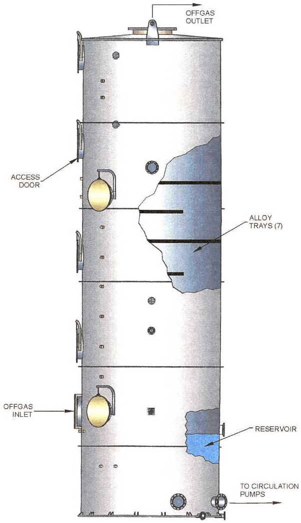
The counter-current dual alkali SO2 scrubber has an overall sulfur dioxide removal efficiency of 99.95%. The discharge of SO2 (sulfur dioxide) to the atmosphere will not exceed 44.9 pounds per hour. The expected SO2 content of the off-gas is 35 parts per million for the base case and 709 parts per million for operation with ores containing higher sulfur levels.
A caustic solution of sodium sulfite is used to scrub the SO2 and produce a slightly acidic sodium bisulfite solution.
The spent solution from the SO2 solution is sent to two regeneration tanks in series. Slaked lime is added to the solution to react with sodium bisulfite precipitating calcium sulfite and calcium sulfate and regenerate sodium sulfite scrubbing solution. Slaked lime is mixed with the spent solution in the smaller tank, and sufficient residence time for precipitation of crystalline calcium sulfite and calcium sulfate is provided in the larger second tank. Since high rates of scaling are expected in the first regeneration tank, a spare standby reactor allows operation when the other requires cleaning. The precipitated solids from the second regeneration are thickened to 25% w/w solids with flocculant addition and sent to the neutralization tanks. The thickener overflow enters an agitated tank, the regenerated solution tank, where it is mixed with fresh soda ash solution. Soda ash make-up is required due to sodium losses in the thickener underflow. A fresh water line is provided for make-up to the regenerated solution tank as required. The regenerated solution is then returned to the SO2 scrubbers, with a small side stream being diverted for preparation of the soda ash solution.
Mist Eliminator and Exhaust Fan
A mist eliminator removes entrained droplets of scrubbing solution from the gas prior to the exhaust fan. The gas pressure is raised to 12.5 inches water gauge by the exhaust fan. This makes allowance for the pressure drop across the CO indicator and catalytic NOx units prior to the stack.
CO Incineration and Heat Recovery
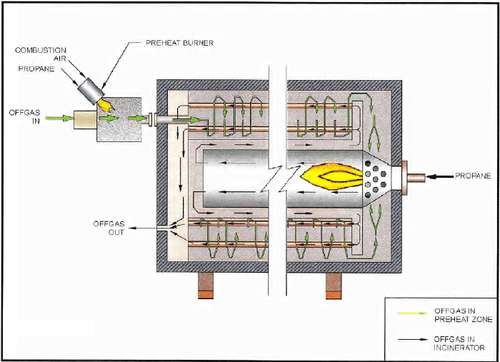
After gas quenching, de-dusting, condensing, wet ESP, Mercury removal and SO2 removal, the off-gas is sent to the CO incinerator and heat recovery unit. The off gas is first pre-heated in a low NOx propane burner from a base case temperature of a 134°F to 300°F, which is above the acid dew point temperature. This prevents acid corrosion of the CO incinerator and heat recuperator where it is further heated to about 1400°F with hot gas from the thermal oxidizer. The off-gas then enters the CO incinerator, where propane is burned in a low NOx burner to heat off-gas to the operating temperature of 1,650°F. The efficiency of CO incineration is 98.5% which reduces the CO level of the off-gas to below the permitted level of 360 parts per million in accordance with air quality standards. The off-gas leaves the heat recuperator at 650°F.
NOx Removal
1 Line
Zeolite catalyst
650 °F inlet temp. 655 °F outlet temp.
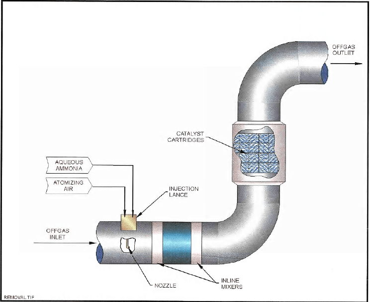
The level of the NOx in the off-gas is lowered to below the permitted level of 250 parts per million by use of a selective catalytic reduction (SCR) unit. The efficiency of NOx reduction is 75%. Aqueous ammonia, injected over a zeolite catalyst, vaporizes into the gas stream, where it reacts with the NOx to produce nitrogen gas and water vapor.
The SCR unit is designed with sufficient catalyst surface area to achieve a normal ammonia slip of 5 parts per million, and guaranteed maximum slip 10 parts per million ammonia. The off-gas from NOx SCR unit is then exhausted through a stack to the atmosphere.

Roaster Flow Sheet — Off Gas
GAS QUENCHER
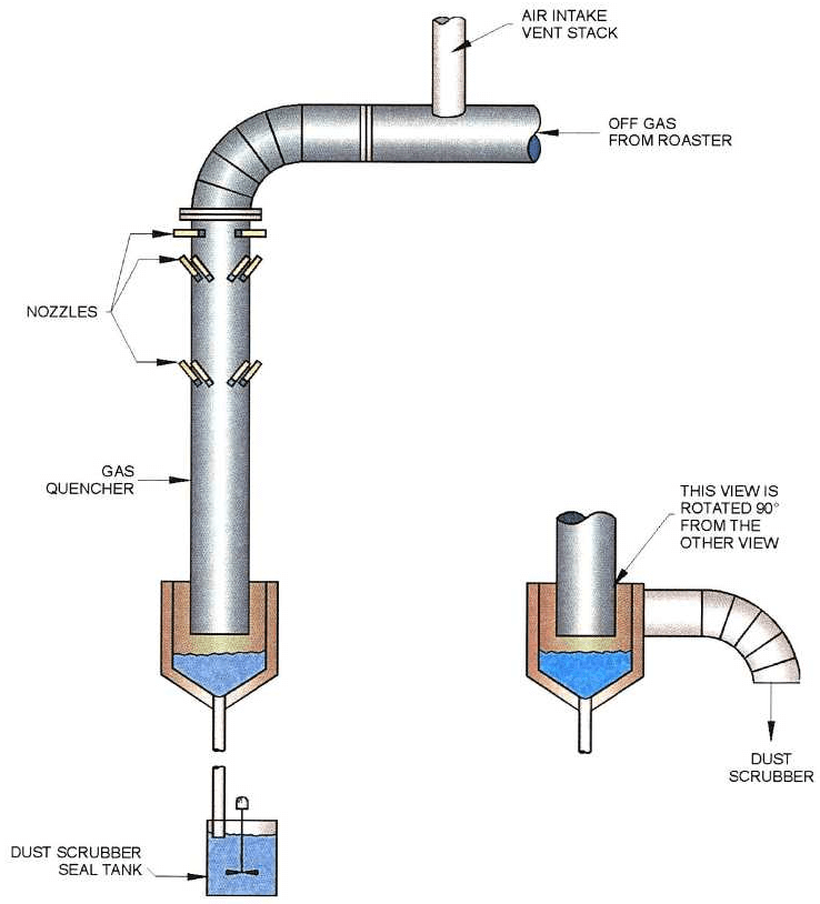
As the offgas contacts the water droplets, most of the water is evaporated and the offgas is cooled. In the collection tank at the bottom of the tower, the offgas (now partially saturated with water vapor) makes a sharp turn before passing through a duct to the dust scrubber. Unevaporated water collects in the collection tank and forms a slurry with some of the particulate matter that was in the offgas. The water/particulate matter slurry flows downward through a pipe to the dust scrubber seal tank, then to the roaster calcine quench tank. The gas quencher and slurry transfer system must be monitored carefully to avoid calcium sulfate (CaSO4) scale buildup.
VENTURI SCRUBBER
SHELL-AND-TUBE HEAT EXCHANGER
WET ELECTROSTATIC PRECIPITATOR
Mercury Scrubber
Simon-Carves Fenco
The tower is located outside; settling tanks are inside mercury removal building
Health Hazards
- Metallic vapor is very poisonous as a liquid or vapor
- Injection causes great thirst, bad stomach pains, nausea and bloody diarrhea
- Inhalation of high concentrations of vapor causes mouth infections, increased saliva, diarrhea and pneumonia
- Chronic poisoning symptoms originate in the nervous system, kidney, and gums
Operation
Runs continuously
Treats 6.1 lb/hr
Gas exiting the scrubber will contain 0.2mg or less of mercury
Gas flows upward through a bed of polypropylene packing. A solution of Mercuric Chloride flowing downward through the packing reacts with the gas to form mercurous chloride (also know as Calomel).
After the gas leaves the packing, it passes through a Mist Eliminator, then the calomel in the form of insoluble crystals is removed from the liquid in the Primary settling tank
The overflow from the primary settling tank reports to the bottom of the tower
The underflow is transferred periodically to the secondary-settling tank where it is held for several days to allow further settling.
Gas leaving the tower out the top goes to the Sulfur Dioxide tower
MERCURY ABSORPTION TOWER
SO2 SCRUBBER
CO THERMAL OXIDIZER
NOx REMOVAL SYSTEM
CIL & NEUTRALIZATION
The neutralization and CIL (carbon-in -leach) processes are two of many steps which much be properly performed to ensure the success of the roasting process. The ore processing activities (such as mining, grinding, and roasting) which occur before the neutralization and CIL process are expensive. The combined costs of these steps compose most of the total operating cost of operation, with no marketable product yet produced. Once the ore reaches the neutralization and CIL section of the plant, the operator must operate the plant in a manner that recovers the metal values from the calcined ore in order to achieve the economic goal of operation.
The gold contained in the ore occurs at an average of. 17 opt (ounces per ton of ore). The gold is within the sulfide mineral matrix, which is not exposed (and therefore can not be dissolved by) a cyanide leach solution. Also the ore contains carbonaceous matter which absorbs gold in the conventional leaching process. For these reasons, The ore is considered to be double refractory. Thus a pretreatment process is required to expose this gold and achieve an acceptable gold recovery by cyanide leaching: The most common pretreatment processes are roasting and acidic pressure leaching. These process oxidize the sulfide minerals, thereby leaving a residue from which the gold can be leached and recovered.
The ore feed rate to the roaster is designed to be 12,000 short tons per day (stpd) based on 90 percent availability. This results in a normal feed rate to the neutralization tanks of 550 tons per hour (tph) = 13,000 tpd.
NEUTRALIZATION
Neutralization – To increase the pH (alkalinity) of the incoming slurry to a pH of approximately 9.5 through the addition of slaked-lime slurry in preparation for cyanide leaching.
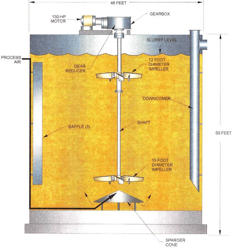
Two tanks – each 48 feet in diameter, 50 feet high, and fitted with a 150 horsepower agitator mechanism, with upper and lower impellers.
Retention time – 1.3 hours to 1.5 hours (12% solids) ( 15,700 GPM )
Quenched calcine from both of the quench tanks is pumped to a manifold feeding the first of two agitated neutralization tanks in series. The tanks provide sufficient residence time to neutralize any acidity with addition of slaked lime slurry. The target pH is 9.5 to prevent formation of hydrogen cyanide gas in the downstream leaching circuit. A rising pH profile is maintained from the quench tank to the neutralization tanks from as low as 3 to 9.5. During periods of high lime addition ahead of the roaster or when some of the high carbonate ores are being treated, this pH profile may be higher, that is from 8 to 9.5.
In addition, neutralization tanks provide sufficient time to reach equilibrium in terms of calcium sulfate content. Experience at other plants predicts a temporary super-saturation in calcium sulfate that can cause extreme scaling in equipment through the quench/neutralization system. It is preferable that this scaling occurs in the slurry while solids are present, since the solids act as seed particles to collect the scale in preference to associated equipment.
By passes are provided to allow each of the tanks to be taken out of service. Each tank overflows to the next and eventually to the calcine thickener. The tanks are emptied for maintenance or de-scaling using sump pumps, which directs material to the thickener deaeration tank.
The neutralization tanks are aerated by process air injection in order to oxidize and precipitate 3 ferrous iron and other metals. These metals consume sodium cyanide in the C.I.L. tanks. Therefore, by minimizing their concentration in solution, sodium cyanide consumption is minimized.
Thickener – Cooling Towers
Neutralized calcine slurry is thickened to 40 to 45% w/w solids before being pumped to the leaching circuit. Flocculant is added to the thickener feedwell after an in-line dilution with thickener overflow to 0.01% w/w. The thickener overflows into an overflow well from which it is pumped to the quench water cooling tower or to flocculant dilution. The cooling tower cools the overflow from approximately 110°F to 70°F.
Three cooling tower cells drain into separate cold wells, allowing each cell to be taken off-line for maintenance as required. Each cold well drain into a common cold well from which the cooled water is pumped back to the two calcine quench areas. Reclaim water is added to the common cold well as make¬up to the cooling tower circuit.
Carbon – in – Leach (CIL) To dissolve gold contained in the neutralized ore slurry by sodium cyanide leaching, and to absorb the dissolved gold onto the surface of activated carbon.
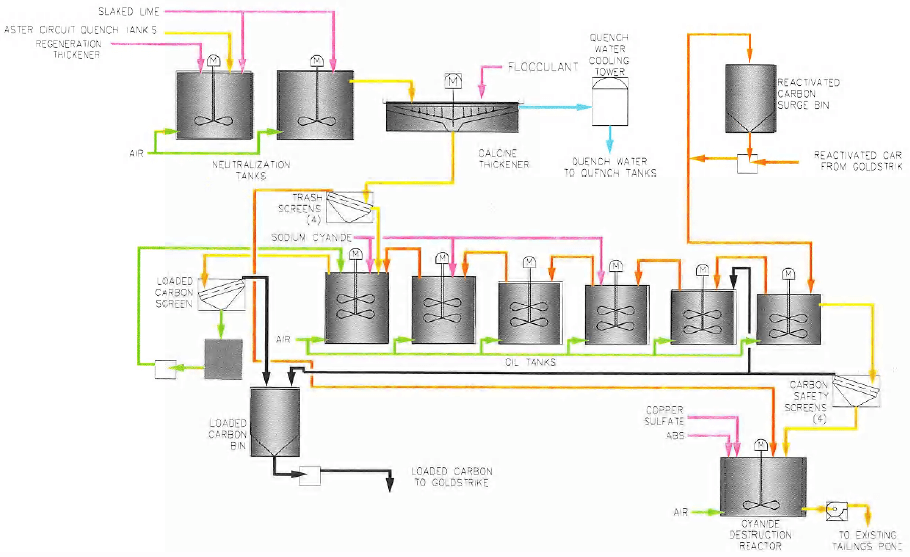
Feed for the C.I.L. circuit is drawn from the calcine thickener. The tramp oversize material in the calcine thickener underflow is removed by vibrating screens. The screen undersize passes to a two-way splitter box prior to entering the C.I.L.
From the splitter box, slurry flows to six C.I.L. tanks sized to provide a total of 16 hours of retention time. Each C.I.L. tank has an agitator and two Kemix screens for carbon retention.
Slurry discharging from the last C.I.L. tank passes vibrating carbon safety screens and is then treated with A.B.S. for cyanide destruction. Detoxified tailings are pumped to the tailing pond for reuse as process water.
Carbon is advanced through the C.l.L. tanks on a shift basis. Loaded carbon (carbon loaded with gold up to 175 o.p.t.) from the first C.l.L. tank is sent to the existing carbon treatment plant for gold removal, electrowinning, refining, and carbon regeneration.
Thickened, neutralized calcine slurry at 40 to 45% w/w solids passes through four trash screens in parallel before entering a manifold that feeds the first tank in the C.I.L. circuit. Any oversize material caught by the trash screens, such as grit from the lime added in the neutralization circuit, flows by gravity to the cyanide destruction reactor with the aid of reclaim water sprays. Reclaim water is used as spray water for the trash screens.
The C.I.L. circuit consists of six agitated tanks in series that provide an overall retention time of 16 hours. Gold is leached by oxidation and sodium cyanide addition to form a cyano-aurate complex.
Carbon, added to absorb the gold in solution, flows counter-current to the slurry through the C.I.L. circuit and is maintained in the slurry at a concentration of 12 grams per liter. The cyano-aurate complex loads onto the carbon to a gold content of 175 troy ounces Au per ton of carbon. The extent of gold dissolution is approximately 91%, including a 1-% loss of soluble gold in the slurry sent to tailings, for an overall recovery of 90%.
Sodium cyanide solution (30%) is added as required in the C.I.L. tanks, one through five, at a rate of one pound of NaCN per ton of dry ore. In addition to gold leaching, cyanide is also consumed by the leaching of other metals. The target concentration of weak acid dissociable cyanide (CN wad) in the discharge is 60 parts per million. There is a provision for the addition of slaked lime to each of the six tanks in order to achieve the target operation pH of 9.5 in each tank. This ensures operation with protective alkalinity, to prevent the production of hydrogen cyanide gas. Oxygen required for the leach reactions is provided by process air injection at a rate of 5 standard cubic feet per minute per 1,000 cubic feet of tank volume.
Slurry is added to the first C.I.L. tank and carbon is added to the sixth tank in order to achieve counter¬current flow. Slurry from each tank overflows to the next tank through two interstage carbon retention screens operating in parallel, which separate carbon to prevent it from moving co-currently with the slurry. A vertical, recessed impeller pump is located in each tank to transfer the carbon-containing slurry to the previous tank. The screens are sized to handle the slurry flowrate plus the slurry recirculated due to counter-current carbon advance.
As with the neutralization tanks, bypass lines are provided to allow each tank to be taken off-line for maintenance with the use of manually placed spools. Bypass lines are also provided for each carbon transfer pump. The tanks are emptied for maintenance using the sump pump, which directs material to the feed line upstream of the trash screens.
Roaster Flow Sheet – Neutralization and C.I.L.
AGITATED NEUTRALIZATION OR CIL TANK
LIME SLAKER
Limestone Ca CO3
Quicklime CaO
Hydrated Lime Ca (HO)2
Lime comes out of ground as limestone, add heat you get Quicklime (3/8 minus) Quicklime plus water, you get hydrated lime.
Notes:
- Material gets very hot during this process
- Better control of pH in regen tanks & Neutralization tank
- Use magnetic Liners
- 1” Balls
TYPICAL VERTICAL LIME SLAKING MILL
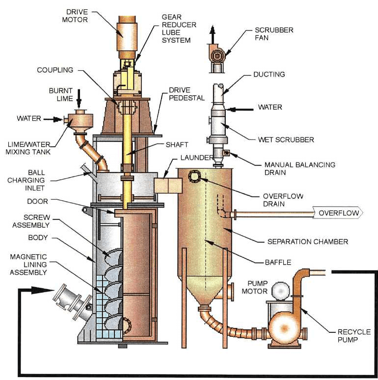
PRINCIPLE OF OPERATION TYPICAL VERTICAL LIME SLAKING MILL
A tower mill consists of a stationary vertical cylindrical body with a rotating screw, or auger, which extends from the top of the mill body almost to the bottom. The auger rotates at a slow speed and circulates a charge of grinding balls inside the mill.
The lime is mixed with reclaim water at the inlet to the mill. As more and more lime/water mixture enters the mill, coarse lime particles, which have not completely reacted with the water, have a tendency to settle out of the mixture and fall toward the bottom of the mill. The auger and the ball charge continue to mix the lime and reclaim water in the bottom of the mill, and the ball charge acts to grind up large particles of lime to allow it to finish reacting with the reclaim water and produce a consistent milk of lime slurry.
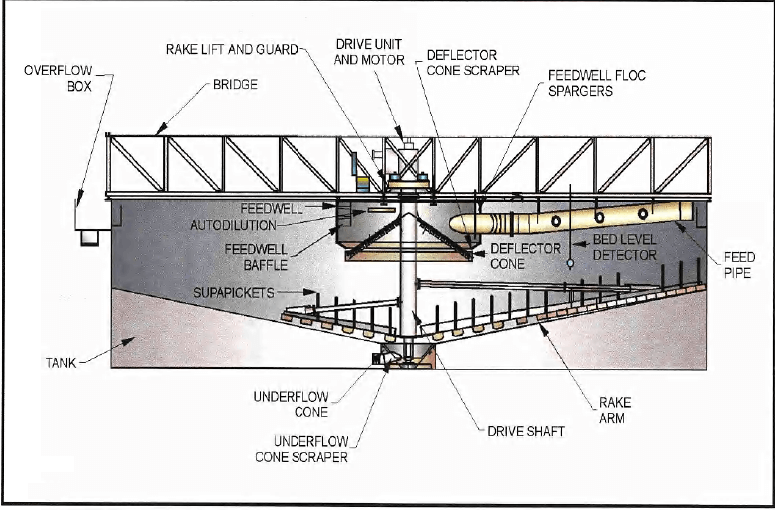
HIGH-CAPACITY THICKENER

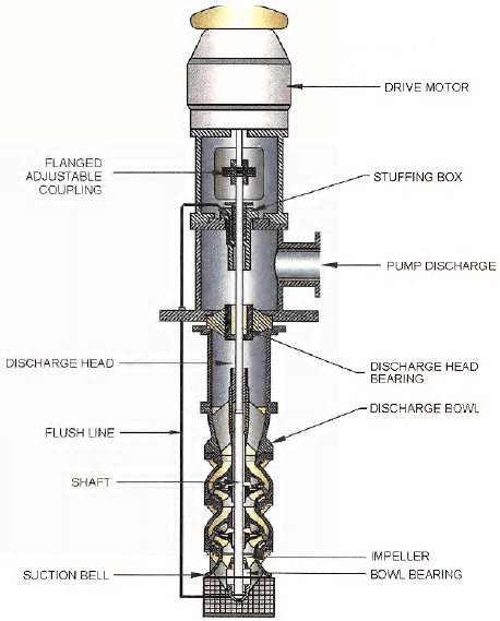
VERTICAL TURBINE PUMP
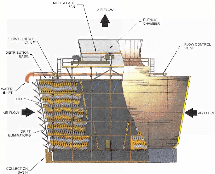
INDUCED DRAFT CROSS FLOW COOLING TOWER
GOLD LEACHING
CIL/Tailings
Six Tanks, 48 foot diameter
150 hp agitators
Interstage screens-Kemix MPS 800, 2 per tank
Carbon striped and regenerated at existing facility
INCO/Air cyanide destruct with Ammonium bi-sulfite
Three sets of tails pumps. Three per line
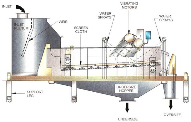
DERRICK VIBRATING SCREEN
CIL Tanks
The goals of the roasting process
Current client requirements for treating low grade complex gold ores have challenged Lurgi to develop new technology. This technology, which is based on over 50 years of fluid bed roasting experience, utilizes Lurgi’s circulating fluid bed (CFB) to treat gold-bearing whole ores and/or concentrates while achieving high gold recovery.
The variety of the chemistry and mineralogy of different gold bearing ores requires professional pilot tests to establish the basis for flowsheets with the necessary flexibility to achieve satisfactory operation and good metallurgical results.
The roasting of gold-bearing minerals is often the first step in the metallurgical process of gold recovery.
Sulfur removal and carbon burn-out are essential and in some cases where arsenic is present, the latter has to be efficiently removed in order to obtain acceptable gold recovery in the subsequent calcine leaching steps and to protect the environment.
It is characteristic of the roasting of gold-containing ores that the highest recoveries are obtained within a rather narrow range of roasting temperatures and oxygen partial pressure in the roaster gas. Ores of sufficient sulfur and carbon content can be treated autothermally. Some ores with low sulfur and carbon contents call for additional heating in order to maintain the roasting reaction.
Since the gold content of most ores is low, large amounts need to be treated in order to ensure attractive economics.
The goals of the roasting process are:
- High sulfur and carbon burn-out
- High arsenic removal and/or fixation
- Uniform and precise temperature control
- Precise control of oxygen
- Safe and controlled combustion of additional fuel when required
- High throughput per roaster unit
- Efficient energy management
- High flexibility in ore range and capacity
Only the circulating fluid bed (CFB) can operate within all of the above specified process requirements.
Notwithstanding this limited temperature range, all the following process criteria have been met:
- High sulfur removal and carbon burn-out
- High arsenic removal, if required
- Exact temperature control
- Accurate control of oxygen partial pressure
- Safe and controlled combustion of support fuels such as coal, kerosene and diesel
- High specific throughput per roaster unit
- Excellent process control due to typical circulating fluidized bed characteristics (uniform temperature profile, gas atmosphere and solids retention time as well as immediate response to changes in feed material).
- In-situ capture of SO2 in the presence of lime/limestone, ore dolomite.
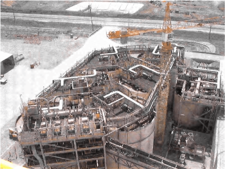
At Cortez Gold Mines in Nevada, the first Lurgi CFB roaster for whole ore roasting has been installed for calcining 90 st/h of gold bearing refractory ore. The ore contains 1.1% sulfide sulfur, 1.1% organic carbon and 2.9% carbonate carbon on average. The limestone introduced to the process with the ore reacts with the SO2 forming gypsum. At a reactor temperature between 680° C and 720° C, SO2 concentrations of about 100 vppm were measured in the off-gas. There was no need for an installation of an SO2 treatment plant.
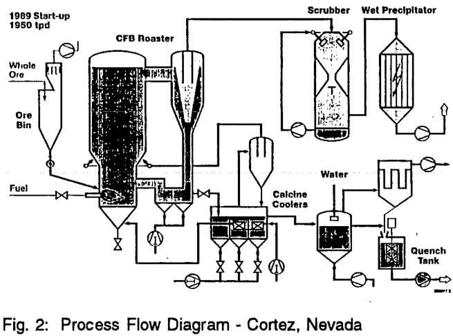
Figure 2 shows a flowsheet (in principle) of this plant.
The plant was commissioned in 1990. The achieved gold recoveries were in the range of 82%. The roaster has been shut down for modifications to the dry grinding plant in order to receive material from new mines. Lurgi has in parallel tested these materials from the new mines in order to optimize the roaster operation in preparation of these materials becoming available.
