Table of Contents
Heap leach gold recovery techniques are employed at Ortiz. Caustic cyanide solutions are sprayed onto crushed rock piles, dissolving the metallic gold from within the rocks and carrying it out as a ‘pregnant’ gold containing solution. The solution is then passed over carbon particles which the gold preferentially precipitates upon. The gold loaded carbon is removed and placed into a desorption circuit, where other caustic solutions redissolve the gold, thus affectively stripping the precious metal values from the carbon. These strip solutions subsequently flow through electrowinning cells where the metal values are precipitated out onto steel wool cathodes for further concentration by more electrolysis and then final sale to an outside refinery.
Crushing and Ore Stackout
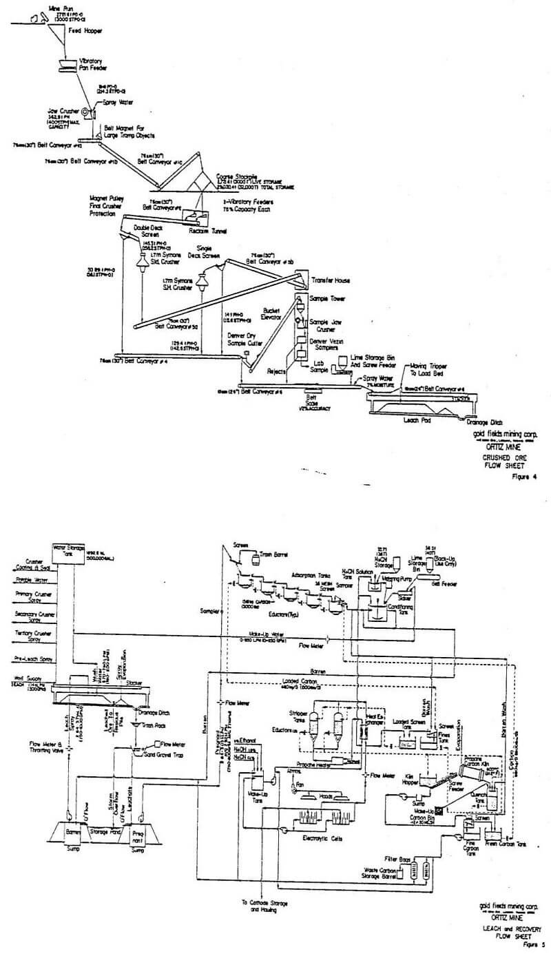
The crushed ore flow sheet is shown in Figure 4. Three stage crushing is employed at Ortiz. An average of 2722 tonnes (3000 st) of ore rock from the mine is dumped daily into an Allis-Chalmers 1016 mm by 1067 am (40 in x 42 in) primary jaw crusher where reduction to about 140 mm (5½ in) takes place. The crushed ore is transported and elevated via inclined conveyor to form a 29,000 tonne fine ore storage pile. This stockpile permits independent operation of the primary and secondary crushers. Ore is drawn as necessary out of the fine ore storage pile through two Eriez vibratory feeders at the bottom of the pile. Conveyors then transport this ore through two cone crushers where final reduction to about 9.5 mm (3/8 in) occurs.
The cone crushing plant is an open circuit. It currently yields 60% passing 9.5 mm (3/8 in) see Table 4, Screen Analysis of Feed to Pad. Material from the fine ore stockpile is fed onto a 1.33 m by 3.66 m (6 ft x 12 ft) double-deck Allis-Chalmers vibrating screen utilizing 12.7 mm (½ in) square screen cloth (9.5 mm effective opening) on the bottom deck. Undersize rock by-passes the cone crusher and feeds straight to the leach pad. Oversize from the double-deck screen feeds through the secondary crusher, a 1.7 m (5½ ft) Symons Standard Cone Crusher equipped with coarse liners set at 25.4 mm (1 in) opening, and then over a 1.83 m by 3.66 m single deck Allis-Chalmers vibrating screen also utilizing a 12.7 mm square screen cloth and into the tertiary crusher. Undersize from the second screen bypasses the tertiary crusher, a 1.7 m Symons Short Head Cone Crusher with fine liners set at 9.5 mm opening, and passes straight to the leach pad.
The combined crushing plant, product is then conveyed across an electronic weightometer to a Thomas Systems Incorporated custom built travelling gantry and stacked 4.5 m (15 ft) high on a reusable impervious leach slab. Current slab capacity is about 136,000 tonnes (150,000 st). The gantry is a unique, fully automated, 61 m (200 ft) span moveable bridge conveyor with tripper and it lays down a flat topped, rectangular, uncompacted rock pile to any desired height from 0 to 4.5 meters. The gantry distributes the fine ore material uniformly through the heap, thus avoiding the segregation (fines core) problem of radial stacker formed heaps, the layering of mobile equipment formed heaps and the compaction problems of dozed flat-top heaps. Besides greatly enhancing recovery rates due to its pile formation characteristics, the gantry has the further advantage of operating at less than a third of comparable mobile equipment costs. Total pad loading operating and maintenance costs are below 15 cents/st.
Leaching
The Leach Slab is constructed of high grade asphalt, 178 mm (7 in) thick. The bottom 51 mm (2 in) is an impervious hydraulic asphalt while sandwiched in the center of the upper asphalt is a further impervious protective rubber membrane. The slab is subdivided by 230 mm (9 in) surface curbs into eight 61 m (200 ft) long by 49 m (160 ft) wide sections or “piles”. A pad, comprised of eight 17,000 tonne (18,750 st) sections; is loaded on average every 10 weeks. The tops of the piles are contiguous but the curbs separate their bases.
Chemical solutions bearing a sodium cyanide (NaCN) concentration averaging 0.07% (varies from 0.05 to 1.5 mg/L depending on sulphide content of ore) and pH adjusted to 10.2 (±1) via lime additions are sprayed over the top of the crushed rock piles at a rate of 0.0018 L/m² (0.005 gallons /ft²) by Rainbird Model F-55 all plastic low angle, impulse sprinklers.
The impulse sprinklers have adjustable trajectory angles and are spaced at 7.6 m (25 ft) centers, this distance adequately overlapping their 12.8 m (42 ft) radius spray circules. Eight separate 102 mm (4 in) pipe headers, fed by the main incoming 254 mm (10 in) barren solution pine line, feed the individual pad sections. The flow through each section’s individual 102 mm pipe header is pressure regulated at a minimum of 13 atm (20 psi) and a maximum of 24 atm (35 psi) depending on wind conditions. Each header has an individual flow totalizer, which allows daily calculation of gold recovery for each section, as well as a continuous flow read-out meter in gallons per minute. This latter instrument allows the operator to equalize spray distribution to all sections. Each 102 mm header then feeds into eight separate 51 mm (2 in) hose lines spaced at 7.6 m intervals containing six sprinklers also spaced at 7.6 m intervals. The sprinklers actually attach to the 51 mm feed hoses via 19 mm (¾ in) diameter tail hoses to allow maximum local adjustment, as well as ensuring complete spray coverage with zero wind loss.
No lime plugging problems have occurred with any of the sprinkler or wiggler types utilized. The addition of 12.7 mm (½ in) crushed pebble lime (CaO) onto the stacker ore feed stream rather than milk of lime through a slaking plant into the barren solution is felt to be the reason for the success in this area. The pebble lime is fed onto the ore stream leaving the cone crushing plant at an average rate of 3.0 kg/t (6 lbs/st) of ore; feed ratio being maintained via electronic connection to the belt weightometer. A slaking plant is available as back-up to the pebble lime plant if necessary. Lime plays a dual role by maintaining a high pH and inhibiting other metals from attack by the cyanide.
The solution percolates down through the heaps dissolving the gold it encounters and ultimately contacting the impermeable barrier of the leach slab. The now ‘pregnant’ solution, containing gold, migrates with the 4% slope of the pad to a collection ditch on the northern edge of the pad.
Gold dissolution in the heaps is denoted by the following chemical equation:
4Au + 8Na CN + O2 +2H2O = 4NaAu (CN)2 + 4NaOH
The pregnant solutions flow via gravity out of the collection ditch, actually an integral part of the leach slab, through trash screens, settling sumps and into concrete storage sumps. Pipelines used on route are 305 mm (12 in) Schedule 20 steel enclosed within 1067 mm(42 in) reinforced concrete tunnels.
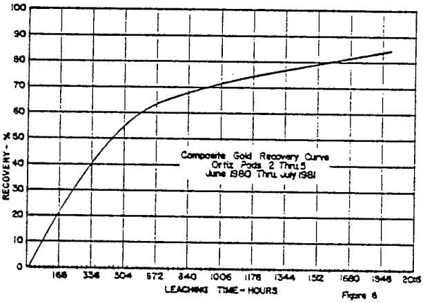
The ore piles are subject to the leaching process for a minimum period of 50 twenty-four hour days. After this period application of cyanide solutions cease and pure water is applied intermittently over a further period of three days to effectively remove any residual cyanides from the leached residue.
The pile is then allowed to drain for four additional days, auger samples are taken of the pile at strategic locations to ensure thorough washing took place and, finally, the material is loaded onto trucks and removed to the residue area for permanent storage.
The residue removal is conducted by the contract miner, generally taking 3 days to remove a single 17,000 tonne pile. The contract miner is paid a fixed additional amount per ton for this service. Normally two of the four mine trucks are utilized along with the rehandle front end loader from the primary crusher. However, the toothed bucket utilized in rehandle has to be exchanged for a flat spade-front bucket for all removal work. This ensures integrity of the slab.
Worthington deep well turbine pumps with high density polymer bearings are used to move solutions from the storage ponds to the Au. plant and back to the leaching piles, with flow meters measuring the rate of flow both ways.
A 5678 kL (1½ million gallon) C.P.E. lined holding pond sited at the side of the drain system can store all the solutions in circulation in the event of a 100 year frequency rain storm and/or a concurrent 24 hour power outage.
Sixteen monitoring wells, nine surrounding the leach slab, four surrounding the storage pond, one below the residue area and two deep wells downstream from the entire plant area, assure that no cyanide has escaped the processing system.
Leaching and Recovery Flow Sheets are shown in Figure 5.
Gold Recovery
Solutions from the pregnant storage sumps moving at 2840 L/min (750 g.p.m.), pass through five countercurrent tower adsorption tanks in series. The 2.44 m (8 ft) diameter x 1.83 m (6 ft) high tanks each contain 1,360 kg (3,000 lbs) of activated carbon granules (actually burnt coconut shells), 12 x 30 mesh in size. The carbon is maintained in an expanded bed scate by the pregnant solutions upflowing through the tanks at a rate of 692 L/min per m². The gold precipitates onto the activated carbon, starting at the highest 1 tank and diminishing in concentration as the solutions gravity drop through the five towers.
Activated carbon has the ability to adsorb the NaAu(CH)2 ion onto its surface. With typical pregnant gold values being 1.0 g/t (0.03 oz/st) and barren solution gold values running between 0.14 and 0.34 g/t (0.004 to 0.010 oz/st) it means 75% of the gold is normally adsorbed by the carbon on a single 7 minute journey through the five towers. With the solutions coming back time and time again for further adsorption this performance is considered quite satisfactory.
Carbon loses adsorption efficiency after many cycles of adsorption and desorption due to “poisoning” by organics inherent in the process. Reactivation brings the carbon back to an “as new” condition. Carbon losses are confined co small particles formed by attrition in the circuit. This undersized material (less than 7 kg per day) is carefully screened out and sold to a smelter for its gold content.
When enough gold-laden carbon has been accumulated in the desorption vessels then a caustic cyanide ‘stripping solution’ containing 1% sodium hydroxide and 5% ethanol is filtered up through the carbon at approximately 87°C (near boiling at Ortiz’s altitude) and low pressure head.
This hot strong caustic solution reverses the adsorption process, thus redissolving and stripping the gold, plus any silver values, from the loaded carbon. The ethanol alcohol merely acts as a carrier to enable the solution to penetrate the carbon particles. The alcohol reduces the strip process from a 72 hour event to a less than 24 hour process.
The strip solutions are routed through one of two parallel Gold Fields custom made 316 stainless steel electrolytic cells, (each with 13 cathodes and anodes), where the gold is electrically deposited from the solution at 350 to 400 A and 6 V onto steel wool cathodes.
2NaAu (CN)2 + 2e = 2Au + 2NaCN
The gold is plated onto 0.9 kg (2 lb) cathodes of 3 stainless steel wool (340 Fine) encased in two simple plastic ‘bread’ trays. The cathode is merely a point of deposit for the gold and takes no part in the reaction. Steel wool is used because of its great surface area and its low cost. Common steel wool originally was utilized but stainless stands up to re-use better. Six wraps of steel wool are utilized within each cathode.
Cathodes load from 600 to 2000 g (20 to 65 oz troy) generally averaging a little less than 50% Au.
Both cells were originally utilized in parallel for the stripping process but it was found that using one cell with a higher voltage (Ortiz initially used 2.5 V) resulted in a higher gold content per cathode. The steel wool cathodes are 685 mm long by 585 mm wide by 76 mm chick, the holders being purchased from Westates of Los Angeles.
In recent days 0.1% NaCN has been added to the strip solution. This improves the quality of gold forming on the cathode by reducing the amount of foreign material plating out with the gold.


