Table of Contents
Project Description
Exploration and development of the project by Rio Algom Ltd. began in 1981. Feasibility and design studies were ongoing in the 1980’s culminating in a decision to develop an open pit mine, a heap leaching facility and an SX-EW plant capable of producing 60,000 tonnes of fine copper per year. Construction began in early 1992 and was completed in early 1994.
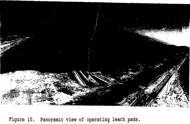
The heap leaching facility consists of nine on-off leach pads with approximate dimensions of 80mx530m each, which are located southwest of the open pit. The leach pads are loaded using a semi-mobile conveyor system.
Geotechnical Considerations
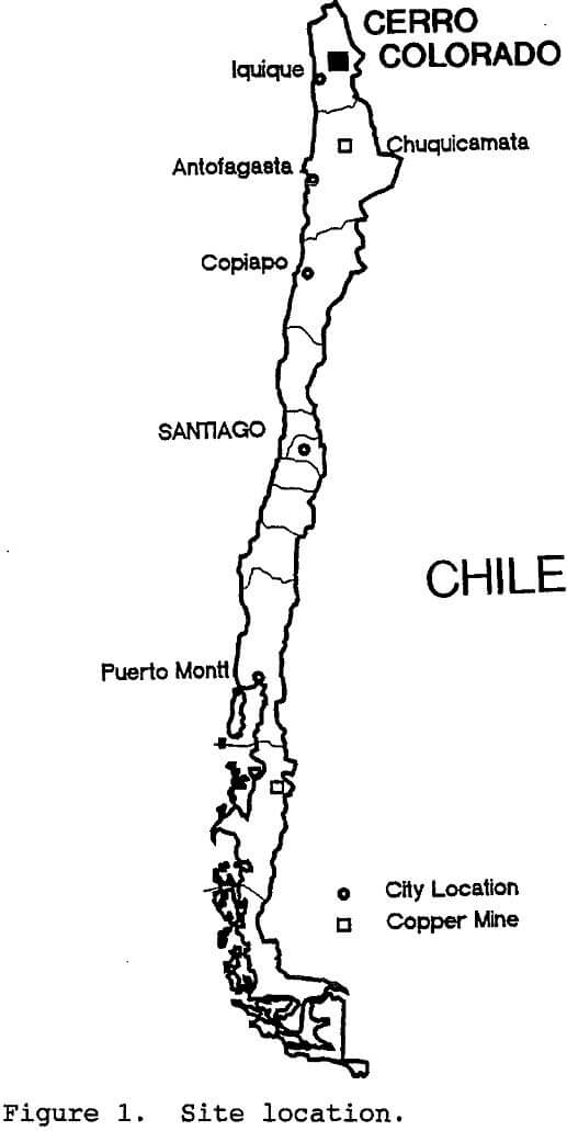
The mine occurs at approximately 2600m (8500 feet) elevation on a large alluvial plain (peneplain) formed on the west flank of the Andes Mountain range. The area is characterized by arid conditions with <10mm of annual precipitation.
Bedrock at the site consists of an assemblage of volcanic and intrusive rocks of Cretaceous age which form the original underlying topography. These rocks are highly weathered in the upper 50 to 100m and are overlain by a regolith derived from in-situ weathering and/or localized transport of soils in post-Cretaceous time.
Leach Pad Design and Construction
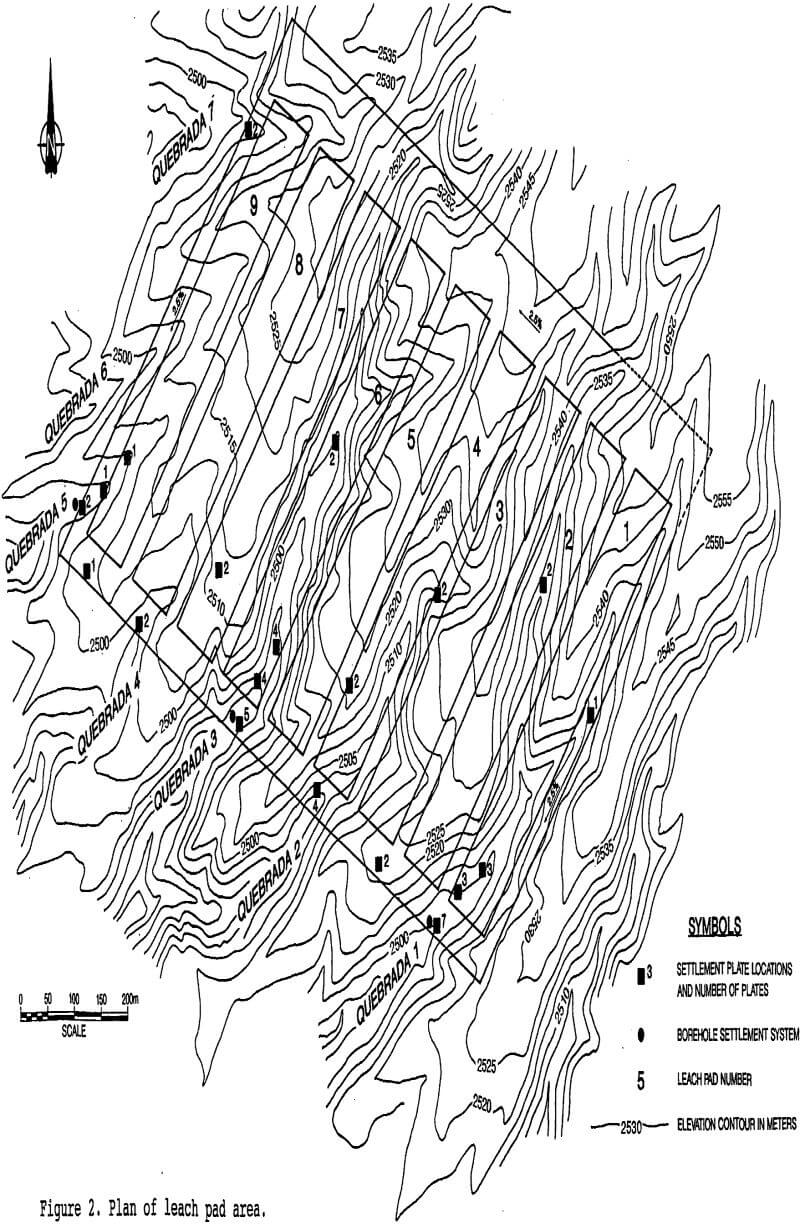
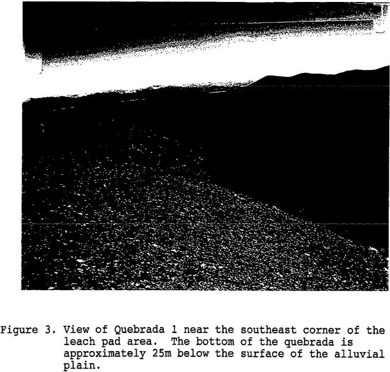
The geometry of quebradas is such that the thickness of fill varies from 0 to 35m from the edges to the center of each quebrada. Cut sections also occupy a portion of the pad area, in order to optimize the fill volume requirements. A total of about 3,000,000m³ of fill was required, which was placed over a period of approximately six months.
Fill Construction Considerations
The main concern with the construction of the fill was to control excessive differential settlements which could occur due to:
i) long term settlements and consolidation of the fill material
ii) uneven fill thickness or uneven compaction
iii) differential settlement at the boundary between the cut and fill sections
iv) construction of the ore piles which have fixed dimensions and height over varying thickness of underlying fill
v) fill collapse if leakage occurred through the liner system
vi) sudden instantaneous settlement during an earthquake
Selection of Fill Materials
The mine had an abundant supply of material from the stripping operation which could be delivered to the site at rates of 30,000 tonnes per day (15,000m³/day) using the mine haul trucks. These materials included chusca, alluvial gravels and weathered bedrock. The properties of chusca and weathered bedrock were questionable and hence the use of these materials was minimized. A large portion of the waste stripping material consisted of generally durable alluvial gravels deposited on top of the weathered bedrock. This material was well graded and consisted mainly of subrounded to subangular particles ranging from sand to boulder size with up to 15% silt. Observations of this material in the field indicated that the material would be easy to place and compact even without use of water in the placement process.
Design and Construction Approach
The above investigations led to the conclusion that the fill for the leach pads could be placed in 4 to 6m lifts using the mine equipment for limited compaction. Controlled lifts were preferred over random dumping because this would result in some compaction being provided by the mine equipment, reduced segregation and a degree of control of the materials placement and relative time for settlement of the entire fill prior
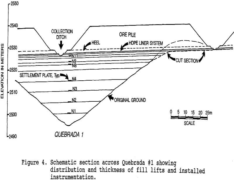
The lift thickness was progressively reduced to 3m, 3m, 2m, 1m and 1m in the upper 10m of the fill to provide additional compaction and to allow the underlying fill additional time to consolidate. This was also recommended to create a denser “mat” in the upper sections of the fill to more effectively distribute the load of the overlying fill and ore piles and to provide additional resistance to disturbance in the upper sections of the fill during an earthquake. This also ensured that the fill was constructed in a more uniform time frame with a more uniform distribution of materials, so that long term settlements would occur more evenly across the entire fill surface.
Instrumentation and Testing
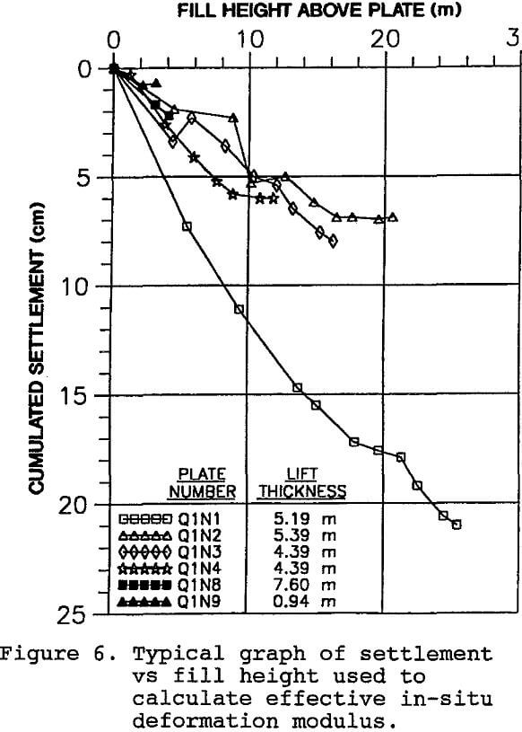
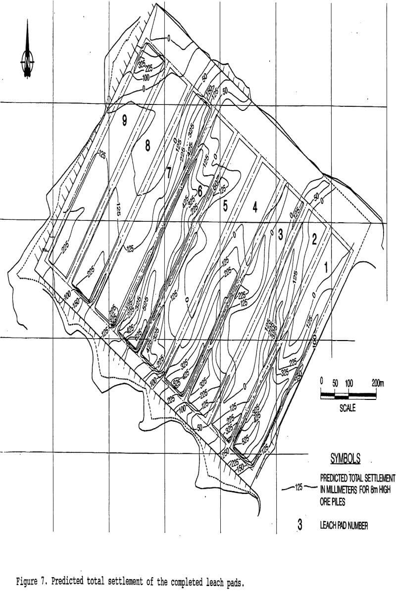
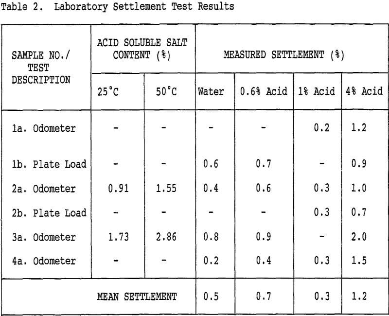
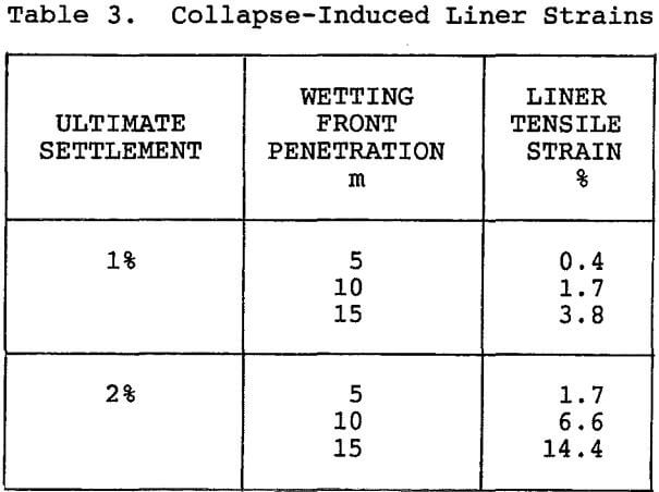
A program of field instrumentation and testing of the fill during and after construction was implemented in order to determine the magnitudes of settlements which occurred during the fill construction and to predict the settlements which might be anticipated during the operational life of the leach pads. These results were to be used to optimize the design of the liner system.
Field testing consisted of in-situ field density tests and plate bearing tests conducted at strategic
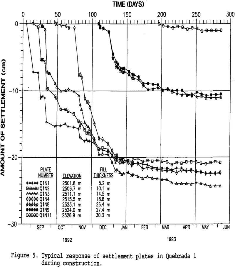
locations in the fill. In general, field density tests were of limited accuracy due to the presence of large cobbles and boulders in the fill material as well as the difficulty in assessing density at depths greater than 2m.
Plate bearing tests, which were conducted using a 750mm (30 inch) diameter steel plate, were of limited value due to the limited effective depth of influence of the test plate with respect to the lift thickness.
Liner System
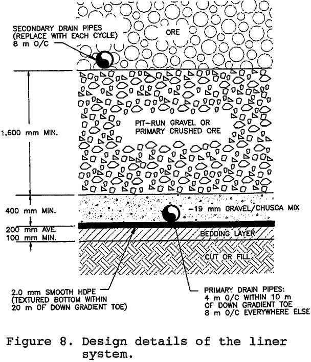
The liner system was designed concurrently with the design and construction of the fill, and the two systems were jointly optimized for cost and performance. The liner system includes the geomembrane, the bedding and cover layers and the heap drainage system.
Design Criteria and Geomembrane Materials
The liner system was designed to meet the following design criteria:
i) remote site with no unusual environmental concerns
ii) construction of the underlying fill in 4 to 6m lifts with limited compaction and potential for differential settlement
iii) repetitive/cyclic loading and unloading by heavy equipment under aggressive operating conditions
iv) optimize installed cost with performance
Tensile and Seam Properties
During unloading of the heaps, relatively high tensile stresses are expected as a result of operations of the loaders and haul trucks. HDPE has the highest strength. In addition, the strength of heat welded HDPE and VLDPE seams is significantly greater than PVC seams which must be glued. Furthermore, heat welded seams are more reliable and easier to test than glued seams. Therefore, PVC was eliminated from further consideration.
Interface Shear Strength
Most heap slope failures occur along the interface between the geomembrane and either the over- or underlying material, whichever is weaker. Six possible interfaces (three possible liner materials and two possible soils) were tested using a 300mm square shear box. Test results are summarized in Table 1.
Simple limit equilibrium stability analyses were conducted using these parameters with smooth and textured
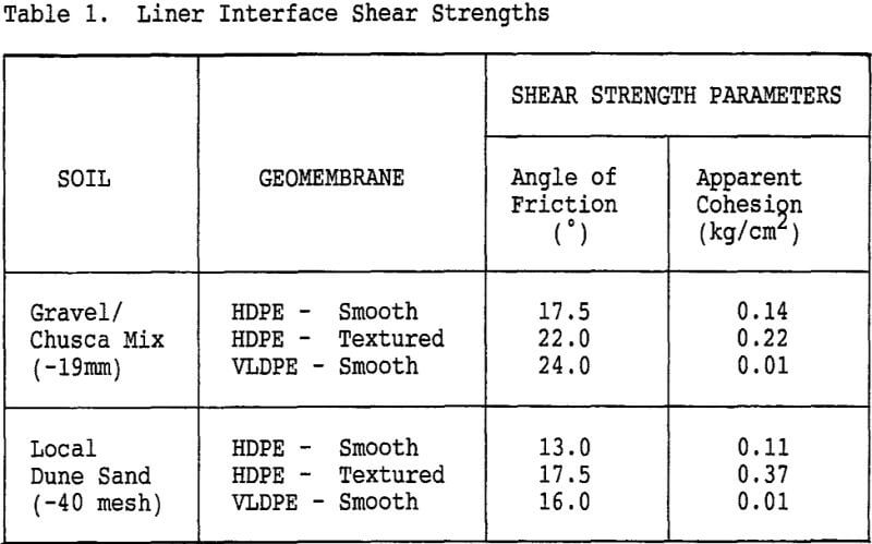
HDPE and smooth VLDPE. A minimum factor of safety of 1.33 was found under static loading. Because of the low heap height of 8m and the non-catastrophic consequences of instability, dynamic stability analyses were not conducted.
Liner System Cross-Section
The selected geomembrane was 2.0mm thick HDPE (increased to 2.5mm in the ditches because of the high solution flow velocities, probable abrasion by suspended granular materials and foot traffic). The bedding layer consisted of a blended mixture of screened (not crushed) -13mm gravel and chusca containing 20 to 50% fines (passing the No. 200 sieve). The bedding material was placed in a nominal 200mm (minimum 100mm) lift, watered and rolled to 100% of Standard Proctor density.
