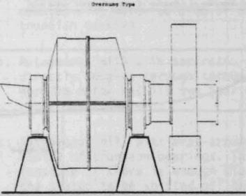
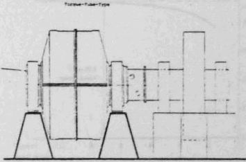
For almost a decade now, very good operating experiences have been gained with a total of 28 gearless ring motor drives in the cement industry, driving tube mills with diameters of 2.5 to 4 meters with drive powers ranging from 3000 to about 5000kW. Why then did the mineral ore processing industry hesitate till 1980 to adopt this successful concept for their undisputably similar application on ball, semi-autogenous, and autogeneous mills? There are a number of good reasons in the eyes of conservative mill builders and operators, the most commonly cited ones of which are as follows:
- No operating experience in this segment of specialized industry.
- More severe environmental conditions in the wet ore grinding process.
- An indifferent attitude of mill builders and electric motor manufacturers towards new drive technologies.
- Limited confidence in solid-state power supply systems,such as frequency converters of the required size.
At this point, one should reflect on the reasons, why such large mills are considered to begin with. After all, one could avoid all the above problem areas by simply staying with smaller mill unit sizes. Under competitive pressures of free markets however, grinding efficiencies and specific energy consumption become key factors in the selection of new equipment.
Mr. Bond a well-known authority in ore grinding applications, established the fact that the specific energy consumption of ball mills decreases with increasing mill diameter – at least within limits (Other experts doubt that this relationship is valid for larger mill diameters, but lacking actual experience in this range, this is of academic interest only). Considering this, ball, semi-autogenous and autogenous mills of ever larger sizes are being built and contemplated. Scandinavian designers have tube mills of 12 meters diameter and 40 meter length on the drawing board, requiring 35,000 kW at 8.5RPM in drive power. The trend towards mammoth mills is clearly there; the present absolute limits are of secondary interest here.
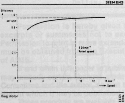
Maximum grinding efficiency and minimum specific energy consumption are found at a specific mill speed. This speed is usually the result of extensive lab tests, based on representative ore samples. Having a variable speed mill allows for adaptation of this speed to changes in the hardness and composition of the ore over the lifetime of the mine, thus optimizing the process as needed.
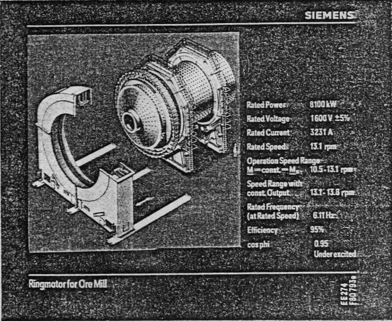
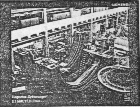
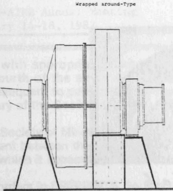
At A/S Sydvaranger, a drive of 8100kW output at 13 RPM was required and geared drives were ruled out for space and technological limitations. A gearless synchronous direct drive of the wrap-around design was selected instead, offering several inherent advantages to the owners and operators :
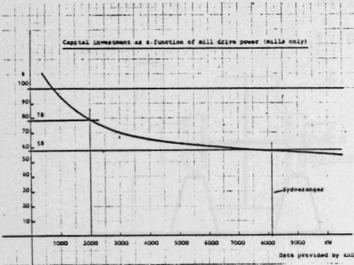
- The new mill with 10x the rated capacity could be installed in place of the old obsolete 100tph mill without disturbing the remaining 13 mills.
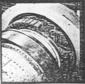
In this design, the rotating field poles of the synchronous motor are saddled directly onto a machined shoulder of the cylindrical mill body itself, thus forming an integral part with the mill. To obtain the rated speed of this ball mill of 13.1RPM, the combination of a very low supply frequency for the motor with a large number of field poles is required, to fulfill the well-known physical relationship
n = 120/2p · f………………………………………………………………..(1)
whereby n = speed in RPM
2p = number of poles
f = frequency in Hz
To shield the motor winding system from the severe and hostile plant environment, a combination of dual sealing rings at the interface to the mill body, with a pressurized motor interior is used. A class of protection of IP44 (totally enclosed, spray-water proof) is thus reached and the motor heat losses are removed via built-in air/water heat exchangers and forced-air fans.
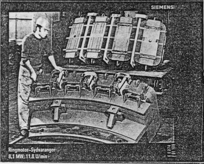
The machine and its accessories were shipped in sizes to fit the available transportation facilities. The single largest pieces were the two stator-halves (55 to each), which could be handled by the existing mill service hoists.The stator was assembled in-front of the partially completed mill body on its sliding foundation. The 14 rotor segments were installed one-by-one on the mill body (which in-turn was field- assembled from three pieces) after its completion, and final alignment was accomplished, by reaming and use of precision ground bolts.
