Table of Contents
The reliability of large diameter, high horsepower ball mill is paramount when large production and minimum downtime is required. The 17 ft. x 56 ft. double compartment ball mill at St. Lawrence Cement Company has the first gearless drive built in North America and has the world’s largest hydrodynamic bearings currently built and running. The machine has seen three years operation and has met its specifications.
Structural Design of Mill and Bearings
The performance of the gearless drive is affected by the structural design of the mill particularly its stiffness characteristics. A knowledge of the mill internal dynamics is required both for the design of the mill and behaviour of the gearless drive.
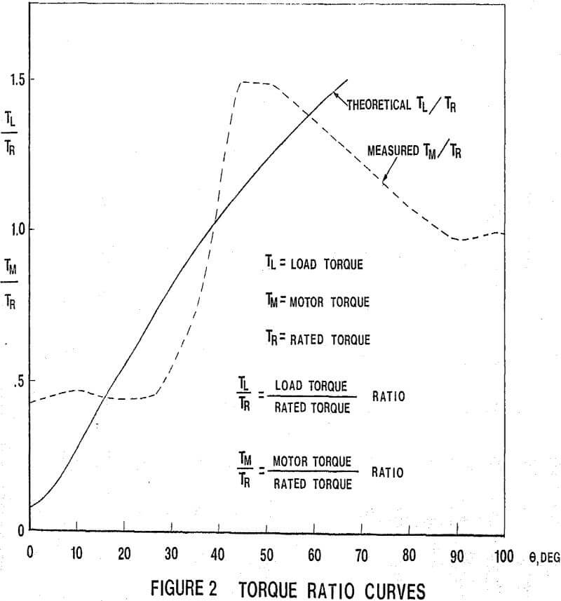
From geometry and known weight of charge and a knowledge of the bearing friction. The load torque curve for various angles can be established. The gearless motor can then be sized to the torque requirements.
The full line representing theoretical values, the dotted line representing measured data. The difference between the curves represents the acceleration of the machine. There is a primary acceleration curve, followed by a secondary deceleration and then by a tertiary acceleration.
Structural Design of the Bearing
The Aerofall Hydrodynamic bearing design has run many years of successful service and sizes and load capacity requirements have increased over the years. Projected diameters up to 240″ and load capacities of 5 x 10 6 lb. are technically feasible and should meet any requirements for large mills in the next decade.
Local shell deformation, out of roundness and slopes at the supports are catered for, by the radial adjustable shoes that pivot freely through 360 degrees. The ability of the bearing to absorb high transient loads associated with possible short circuit conditions is also a useful feature particularly when a mill and charge weighing 5 million pounds wants to crawl out of the bearing and on to the floor.
Operational Results
With this cement installation, it is possible to find the optimum production by changing the following:
a) Mill speed from 13.0 rpm to 14.5 rpm (68.4% to 76.31% of critical speed).
b) Diaphragm opening (in division head from open to closed position).
c) Auxiliary fan blade speed from 50 to 150 rpm.
d) Feed of clinker, gypsum and gypsum tailings.
The optimum operation was found after 3000 hours running. The capacity was some 10% over the guaranteed capacity. This large mill 17′ x 56′ is not less efficient than a smaller mill 10′ x 28′ used in comparative tests.
Maintenance of “Gearless Drive” Mill
The lubrication system. This depended on gravity feed of oil to the bearing pads. There has been no mechanical trouble due to this. This system is being revised for better temperature control and pressure pumping of oil to the bearing pads.
Pressure method of ensuring lift with high pressure pumps before starting. Depending on oil temperature conditions and thermal input to the mill affecting oil viscosity a hydrostatic lift check with a dial indicator has to be performed to ensure lift of .0015 inches before start up.
The drive is in the “self-controlled” mode in that the rotor speed directly determines the output frequency of the cycloconverter. It is thus impossible to operate out of synchronism and the drive has the same characteristics as a DC motor drive. Thus if the drive is overloaded, it will droop down to a new equilibrium value. If the overload is severe enough it will stall. The stator current is limited to 1.4 pu., and protective circuitry will limit the duration of this period.
It should be noted that with the 1.4 pu stator current and maximum rotor current a maximum torque of 1.7 pu is produced. This greatly reduces inrush starting current compared with conventional synchronous motor starting modes.
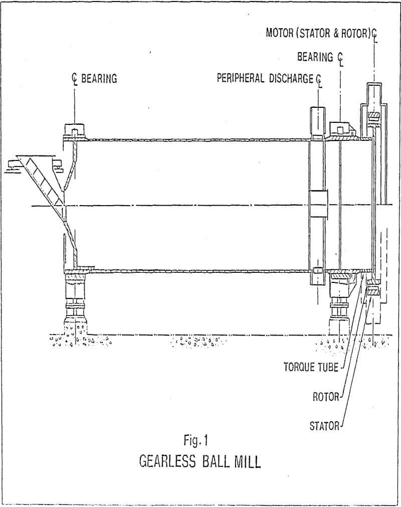
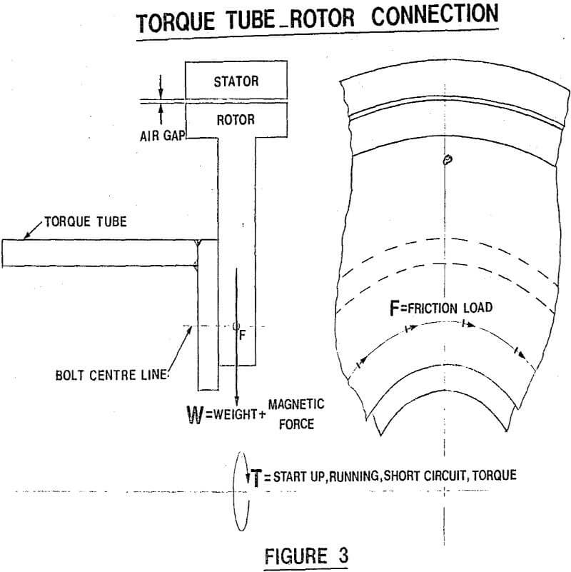
The mill is powered by a synchronous motor rated 8750 HP, 14.5 rpm, 1.0. PF, 1900 volts, 3 phase, 4.84 Hz, 1.0 service factor, Class B insulation. The motor is mounted outside the mill discharge end bearing with the rotor overhung on a torque tube extension of the mill. This arrangement with air to water heat exchanger, air circulating blowers and a pressurized enclosure has performed well in the severe dust environment.
The rotor slip rings, housed in a separate compartment, continue to exhibit a good collection surface. During commissioning and subsequent operation the motor has been started many times without ever failing to deliver adequate torque. The mill loading was built up during 1973 and 1974 to the present value. The plot of “Stator Current vs Mill Loading” is based upon the field data obtained as shown in Fig. 14. 32% charge = 557 short tons of balls. The present loading is 29.4% (517 tons).


