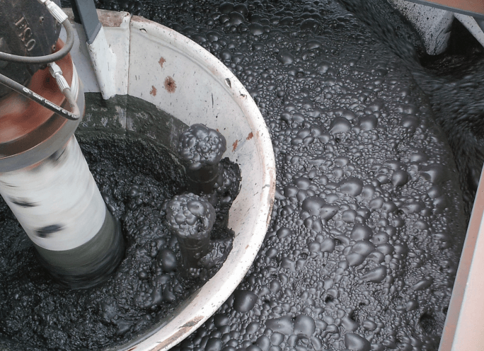
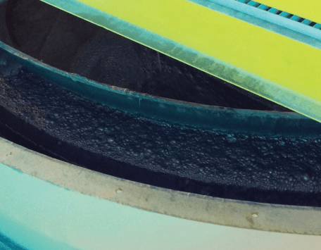
The concept of froth crowders and was developed in the early 1950s. The need for crowding froth out of a flotation cell grew along with the size of flotation machines and their cells.
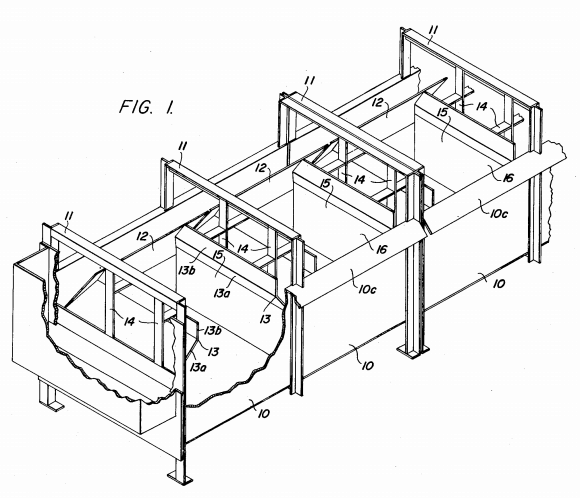
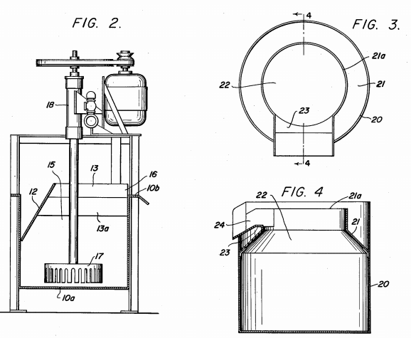
The 1st froth crowder device was patented in 1956 (Fig 1 and Fig 2). What I call the crowder plate is Piece/Item # 12 on the drawings below. What those plates would do it force the flotation froth out of the cell, pushing it away from the back of the cell and preventing froth drop-out back into the pulp/slurry. In a flotation cell, a crowder device, effectively reduces the cell/tank’s open/surface area. In the right application, it will improve the concentrate grade and recovery at reduced mass-pull as it somewhat speeds up flotation kinetics and also reduce frother requirements
 |
 |
In 1997 a new way of crowding out froth was developed for large flotation cells.
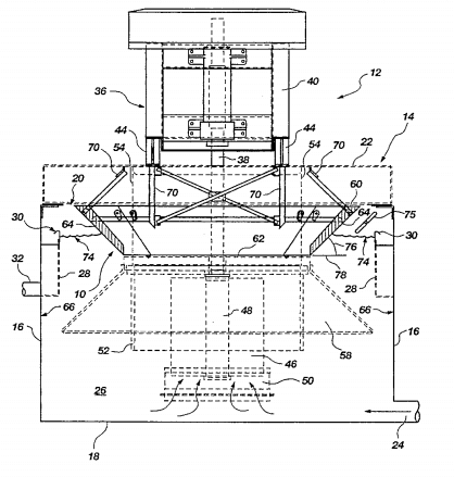
The size of the crowder relates to the size of the cell as well as the ore’s head grade. The richer deposits need less crowding as opposed to poorer ores.
Froth Crowder Design and Sizing:
As too high or too low an FCR has a negative effect on froth transportation, effectiveness and flotation cell performance, what is the optimum range?
Based on experience and analysis of plant data, the recommendations shown in Fig.1 above, have been published as acceptable FCR guidelines from which to begin.
The amount of froth crowding at the top of a flotation cell determines the amount of froth surface area for a given flotation cell. During the project design phase, the optimum amount of froth crowding is determined using design data in conjunction with the accepted Froth Carry Rate guidelines above, and experience of particular applications. By adjusting the size of the central froth crowder (booster cone), as well as perimeter tank crowding and the concentrate launders themselves, the froth surface area is adjusted to an optimum level. Outotec.
