Table of Contents
There used to be a time when bins were designed for total volume and placed in any available place of the plant. Poke holes were provided and feed was maintained by manual prodding, lancing, hammering, and by various mechanical flow-promoting devices. Little thought was given to what occurred inside the bins and why materials did not flow. Indeed, such mental effort was hard to justify while low-cost manual labor was plentiful, quality standards low, and rates of feed moderate.
Typical Storage and Flow Problems
In order to design an efficient storage plant or contact-bed reactor it is necessary to be aware of the problems which can arise in flow and storage. The typical problems are:
No flow: a stable arch (dome) or rathole develops within the solid and flow ceases.
Erratic flow: momentary arches form within the solid; ratholes empty out partly or completely, then collapse. Density of the stream swings within wide limits.
Flashing: powders in erratic flow aerate, fluidize and flush. While air-locks can be used to prevent flushing they do not eliminate erratic flow.
Insufficient flow: the volumetric rate of gravity flow through an orifice depends on the stored solid. Coarse dry solids flow at a high rate, closely approaching the maximum theoretical value. Powders, solids coated with viscous liquids, flow at a very much lower rate.
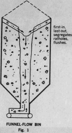
Lack of designed capacity: a large part of the stored solid remains stable around a rathole. Severe vibration or manual prodding is required to continue flow.
Segregation: a solid segregates in a bin and the separate fractions feed out at different times or from different outlets.
Flow Patterns
Funnel-flow bins. Most existing bins are of the funnel-flow type. The solid flows toward the outlet through a channel extending upwards from the feeder or gate. The channel expands from the outlet to a circular shape and is surrounded by non-flowing solid. As the solid flows out, the level of the solid in the channel drops, layers of the non-flowing solid slough off the top of the surrounding mass and slide into the channel.
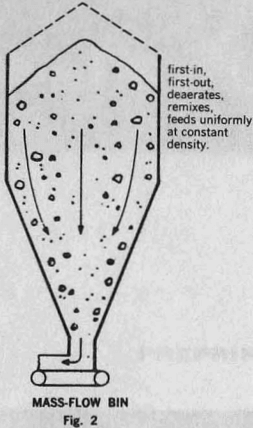
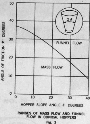
Mass-flow bins. If all the solid is in motion whenever any of it is drawn out, then such a bin is of the mass-flow type. The division between mass flow and funnel flow for conical hoppers. θ is the half included angle of the cone, ∅’ is the kinematic angle of friction between the stored solid and the wall of the cone. When the cone is sufficiently steep and smooth (small values of θ and ∅’) the channel expands from the outlet upward along the walls of the cone, and mass-flow occurs. If the cone is not sufficiently steep and smooth, funnel flow occurs.
Hopper-feeder unit. In mass-flow bins, the hopper,and the feeder should be regarded as an integral unit. The feeder should draw the solid through the whole area of the hopper outlet. This requirement is not met by all feeders. For instance, it is not met by a screw feeder of constant pitch and diameter; such a feeder draws solid from the end of the screw.
Expanded-flow bins. In many cases adequate operation is obtained by using a short mass-flow hopper-feeder unit under a funnel-flow bin. The mass-flow hopper serves to expand the size of the flow channel to a dimension which eliminates the possibility of ratholing, ensures deaeration and smooth flow, and reduces segregation to acceptable levels.
Dimension of Outlet
The flow-function for dry sand coincides with the p-axis because dry sand cannot be consolidated to form a stable cylinder within the range of pressures encountered in bins; f = 0, the flow criterion is always satisfied, and this analysis does not determine a minimum outlet dimension. Dry sand is perfectly free-flowing and cannot form a stable dome or rathole. With some moisture added, sand gains strength. Since, in this case, strength is due entirely to the surface tension of water, the increase of strength with pressure p is slight, the flow-function curve rises but little with p. A powder may have strength rising more steeply with pressure. The powder and moist sand have points of intersection which determine minimum outlet dimensions.
The critical bin dimensions are readily found once the flow-function of a given solid has been determined. This analysis is also available for mass-flow hoppers of shapes other than conical and for funnel-flow bins. A funnel-flow bin has two flow-factors, and the outlet is computed for no-doming and for no-piping: the outlet has to be sufficiently large not only for a dome to collapse but also for the walls of the flow channel to collapse so that a stable rathole does not develop as the solid is drawn out of the channel.


