Table of Contents
There are many methods of handling sand and slime from metallurgical operations, but in this article the draining and conveying of waste products from flotation processes will be specially dealt with, the methods given being those in use at the leading flotation plants in Australia.
DRAINING AND DEWATERING
It is generally advisable to thoroughly dewater the residue from flotation treatment in order to form a closed circuit of liquor. This maintains constant conditions throughout the plant and avoids waste of oil, which would be carried away by the solution with the tailing. The methods that may be used for this purpose are :
- (a) Filtering in vats;
- (b) combination of a submerged draining-belt and Dorr thickeners;
- (c) combination of Caldecott diaphragm-cones, draining-belt, and Dorr thickeners, and
- (d) combination of Dorr classifiers and Dorr thickeners.
FILTERING IN VATS
In this system, shown in Fig. 50, the pulp from flotation is run direct into vats. These are usually 15 ft. diam., their depth varying from 10 to 20 ft. In the centre of each, and before filling, a tube or pipe, 15 in. diam., that fits over the circular discharge-hole, is inserted. When the vat is ready for emptying, this tube is lifted out, a large proportion of the tailing falling through the centre hole onto a conveyor underneath. The remainder is afterward shoveled upon the same conveyor.
A wooden frame, not shown in the sketch, is erected above the vat to support the lifting-device, a screw-block being used to raise the pipe to the desired height. This operation is afterward carried out by an ordinary block and tackle. The vat may be made of wood or iron, and the height to which it may be constructed is controlled by local conditions, such as the design of the plant, and the nature and fineness of the material to be filtered. It is however, apparent that the greater the height that can be economically employed, the less the labor required, as a proportionately large amount drops through the centre of the vat without shoveling. This would tend to make the inner tube too long to be handled conveniently, but the difficulty has been overcome by making the tube in sections, each of which is lifted in its turn from the top as emptying proceeds.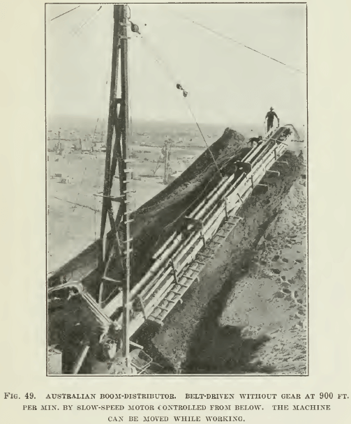
The time of filtering is arranged according to the number of vats employed, but it is the usual practice to run the pulp through a number in series, so that the slime settles from the solution. Thus, if six vats are in use, one may be draining and another emptying, while the remainder would be used for the pulp flowing, in series, through them. The filtered water is carried off by a number of pipes at the bottom of each vat. Under certain conditions a suction-pump is connected to these pipes to assist the filtering, but this is not the usual practice. As a filtering medium, cocoa-nut matting is used generally.
After a vat has been emptied, the tube is dropped into the discharge-hole, two lugs, one on each side keeping it in position. The open space round the tube is then filled with clay. It is advisable to have the bottom of the vat’ six feet above the ground- level to allow of easy access to the conveyor underneath. At the spot where the sand is discharged upon the conveyor-belt, guide- doors are arranged parallel with the belt to prevent sand going over its edge, and the number of idlers under the conveyor is increased to prevent it sagging under a rush of feed. The conveyor is usually a flat- belt, 24 in. wide, traveling at 350 to 450 ft. per minute, 4-in. iron idlers being used.
This method has many excellent features; its advantages are:
- The moisture of the drained tailing is less than in any other system;
- the slime is drained at the same time as the sand;
- dams for handling the slime and the cost of labor on same are eliminated;
- dusting troubles are minimized on the dump, owing to the slime helping to set the tailing;
- the angle of repose of the dump is increased, thus enabling more sand to be stacked per unit of ground-area;
- no trouble with conveyors handling tailing will cause a stoppage in the main plant;
- accurate sampling of products is possible, enabling shift-work to be kept under control.
The disadvantages are:
- High initial cost of erection;
- relatively high cost of labor in emptying vats;
- clarification of solution is not usually as complete as is the case with other methods.
COMBINATION OF DRAINAGE-BELT AND THICKENERS
The idea of the submerged draining-belt, I think, was first introduced in connection with the Elmore process in order to overcome the difficulty of discharging the residual pulp without upsetting the vacuum in the flotation apparatus. In this system the belt runs inside an iron trough filled with water, being forced into a semi-circular shape by means of a spherical pulley, as shown in sketch, Fig. 51. The belt travels under water for a certain distance, rising at a slope of 15 to 20° onto the head pulley.
The drive is usually from the tail-end by means of a worm-wheel on the tail-pulley shafting. This tail-pulley is generally 6 ft. diam., and is faced on the outside with wooden boards to give the belt a better grip. The feed is, preferably, distributed to the belt by means of an iron launder with holes in the bottom, wooden guides being arranged to guard against sand getting between the under side of the belt and the trough. 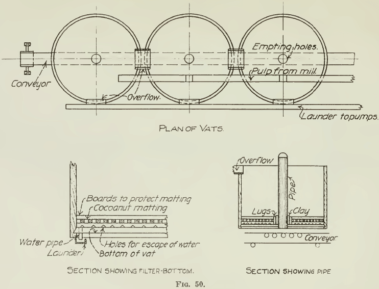 The trough has side launders attached to carry the overflow to Dorr thickeners, the number of the latter depending on general conditions, such as nature of slime, amount of water in circulation, etc. The submerged belt forms an excellent desliming system, by reason of the classification in the trough; its capacity is 4000 or more tons a week of mixed slime and sand The draining of the sand is accomplished as it rises from the surface of the liquid in the trough to the head pulley.
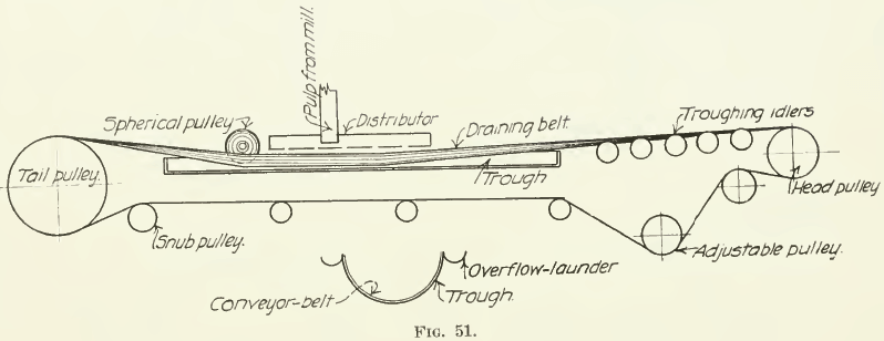
In order to accelerate this draining action, a bumper is usually employed. This consists of an idler driven by two eccentrics. The vibration caused on the belt by the idler striking it underneath displaces a larger quantity of water from the sand, and thus reduces the proportion of moisture in the final product. An iron scraper is used for removing the tailing from the draining-belt; it may be kept under pressure by means of iron springs. This method is very good, especially where the room available for drainage is limited. It is also convenient where the height of the flotation-plant above the ground is small.
The life of the belt is less than that of an ordinary draining-belt, owing to the heavy pressure of the spherical roller, and the action of the hot circuit-liquors in which the belt is submerged. The labor for attendance is small. This method is at present in use on two of the large flotation plants at Broken Hill.
COMBINATION OF CONES, DRAINING-BELT, AND THICKENERS
This method, diagrammatically illustrated in Fig. 52, has been installed in the latest flotation-plant at Broken Hill. The size of the Caldecott cones usually employed is 12 ft. diam. and 10 ft. deep, the diaphragm being 2 ft. to 2 ft. 6 in. from the bottom of the cone. In most cases a plate-diaphragm is used, but the introduction of an iron ball to serve the same purpose has been most successful. Where a cone of this type is used as a thickener, rather than as a slime-classifier, more pulp may be thickened, as the height of pulp need not be so finely adjusted. Still, it is customary to keep the level of the sand two feet from the top of the cone, as measured in the centre. The feed usually passes into these cones through a centre of the Callow type.
To remove the thickened pulp continuously and divert it onto the draining-belt, an ordinary plug may be used with advantage, provided coarse rubbish has been removed previously. Another successful device is a plug-valvc or a plug worked from the top, fitting into a seat at the bottom of the cone. The type of draining- belt employed is 36 in. wide. The belt rises gradually, about 1 in 60, from the tail-pulley, the last 30 ft. of the slope being increased to about 20°. The belt-speed is 20 to 30 ft. per min., both ordinary and troughing idlers, of 6-in. diam., being used. As the operation of the belt is slow, wooden idlers working in cast-iron ‘dead-eyes’ can be successfully used for the horizontal idlers, the troughing- idlers being of the usual type.
The drive is at the head end, double gearing for speed reduction being employed. The head-pulley is generally 5 ft. diam., the snub- pulley 18 in. diam., and arc of contact 200 to 250°. The tail-pulley is usually 2 ft. diam. Rubber belting on the face of these pulleys reduces the slip, thereby increasing the power-efficiency and the life of the belt.
The overflow from the Caldecott cones goes into one or more Dorr thickeners, according to requirements, the underflow from the thickeners, as in other methods, being handled with flooded suction-
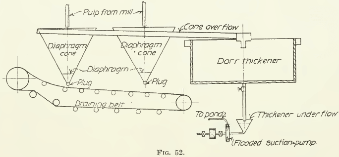
pumps. Attempts to mix the underflow from the Dorr thickener with pulp on the draining-belt in order to convey them together to the pump have not so far proved successful. For the control of the underflow from Dorr thickeners the hydrometer method (described in ‘Rand Metallurgical Practice’) has proved quite satisfactory, a constant pulp, with Broken Hill slime of 50% solid being easily maintained. This method is considered a good one, because the cost of labor is low, the life of the draining-belt is prolonged, and the cost of maintenance is small. Adequate head-room is, however, necessary for the erection of the cones; in some cases elevation is essential. A disadvantage is that a stoppage of the dump-belts causes a stoppage of the whole plant.
COMBINATION OF CLASSIFIERS AND THICKENERS
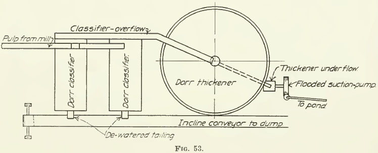
This method has not, to my knowledge, yet been adopted at any plant in Australia, but the great success that it has achieved at cyanide plants in America shows that it could be applied to the handling of tailing and slime products at Broken Hill. The usual type of Dorr classifier, however, would have to be especially lengthened to cause extra draining of the sand product. Owing to the regular working of these machines the usual draining-belt may be discarded. At the same time very little head-room would be required. This method is illustrated in Fig. 53, which shows the classifiers delivering direct onto the inclined belt. It has, however, the same disadvantage as the method last mentioned, in that it does not make the treatment- plant independent of the dump-belt stoppages. The cost of erection and maintenance would, however, be small.
HANDLING OF DRAINED PRODUCTS
Tailing may be handled in the following ways:
- (a) Inclined conveyor-belts and boom-stackers,
- (b) aerial trams,
- (c) tracking, and
- (d) sluicing.
INCLINED CONVEYOR-BELTS AND BOOM-STACKERS
The usual angle for an inclined conveyor is 20° ; where possible the conveyor should be driven from the head-end. Where the head-end is high above the ground, the drive should be either from the tail-end or from a large centre-pulley, midway along the belt, having a snub-pulley at each side above it, the centre-pulley being 6 to 8 ft. diam. and resting, preferably, on a concrete base.
The inclined conveyor is first of all built on trestles at the angle required. As the size of the dump increases, the conveyor is extended in the form of a cantilever, held by guy-ropes from the upright trestles in the dump. A belt to handle 40 to 50 tons per hour would require to be one of 24 in. six-ply rubber built on 3 to 10-in. stringers, placed 3-ft. centres. If driven from the head-end, the driving pulley should be 5 ft. diam. gear-driven, the tail-pulley being 2 ft. diameter.
The Australian practice is to use separate rollers and troughing- idlers instead of a combination idler. This practice is simple; the idlers can be more easily lubricated. The best size of roller is 4 in. diam. It is usually made of steel pipe shrunk onto cast-iron end pieces. A favorite practice is to have idlers and dead-eyes on the top of the same stringers, the loaded and return belt running on rollers supported by the same, and being about three inches apart.
The top rollers are usually spaced 4 to 6 ft. centres, the return idlers being spaced at twice this distance apart. Wooden rollers for fast belts of this type are not satisfactory.
In calculating the power required for this type of belt it is well to remember that the horsepower lost in friction per 100 ft. varies inversely as the length of the belt, averaging from 2 to 6 hp. per 100 ft. A tightening arrangement is usually fixed on the tail-pulley of this type of belt to cause it to run true and take up any unnecessary slack. When an inclined conveyor has been carried out to an economical distance, the tailing at its end is made into a bed for a boom-stacker. This is an iron pole, which is held in position by four strong guy-ropes. Attached to the pole is an iron lattice-girder, which is supported similar to a cantilever by guy-ropes attached to the pole itself. This boom-stacker rests on a steel ball in a cup-shaped receiving device, which enables it to swing around as desired. The weight of the boom-stacker is spread over a large area by means of a number of heavy timbers resting in the prepared foundation on the dump. The conveyor on the boom-stacker is driven by a motor fixed behind the boom, and traveling around with it.
AERIAL TRAMS
These are so well known that they need no description here. For moderate tonnage they are seldom used, as a bin is required and two men loading and operating trucks.
HANDLING OF SLIME
The pulp from Dorr thickeners is either transferred by flooded-suction centrifugal pumps or three-throw pumps, or else elevated by an ordinary belt-elevator. Where there is room for a slime-dam close to the treatment-plant, the belt-elevator, which is a very economical system of elevation, may be used. In other cases centrifugal pumps are resorted to. The thickened pulp may also be delivered to dams or sprayed onto the surface of sand- dumps. To remove the drained water it is preferable to use a wooden box-launder. This consists of two box-launders connected in the form of a right angle, and fixed in position at the starting of the building of the dam. The horizontal portion of the launder is laid 12 ft. inside the dam, and is carried to the water-sump outside it. The vertical portion passes through the slime and is bored with holes, which are plugged from the bottom upward as the building of the dam proceeds. Probably the best method of handling slime-pulp is to pump it through a nozzle onto the surface of sand-dumps. By such means it may be sprayed evenly all over the dump. This does away with dams, and checks the dust rising from the sand-dump. The idea was first originated in South Africa, and has only lately been introduced into Australia.
