 This is an overview of setting up and conducting a flotation rate test. The test is a means of determining the flotation characteristics of an ore. It is conducted in a laboratory scale cell usually with a volume of two point five litres. The intention is to generate relationships of cumulative recovery, mass pull and grade versus time and use these to evaluate the floatability of metal, mineral and gang. The video is not intended to be a detailed explanation of how to conduct a rate test. For that, download the test procedure shown here below.
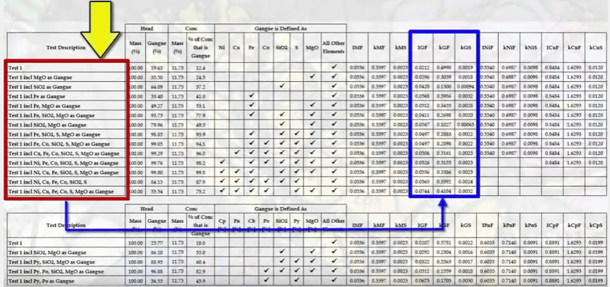 The purpose of this video is to outline the important aspects of setting up the test to ensure that flotation characteristics are correctly measured and the resulting data can be properly interpreted. How the data is used to determine flotation kinetics is a subject of a separate video. The key aspects are:
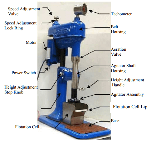
- the types and setup of the laboratory cell;
- sample to be tested,
- test conditions and
- how the test is conducted.
The standard laboratory cell and cell size for many decades has been the Denver D12 with 2.5 litre stainless steel cell.
This comes standard with 73 millimeter diameter rotor and a stator of 80 millimeters inside diameter. The 2.5 L cell has an operating volume of about 2 L and takes 1 kilogram of solids, giving a pulp density of 32% solids by mass. Air is self-induced through a valve on the shaft. Alternately air can be supplied from a compressor and controlled by valve.
What rotor speed is used on the D12 in a flotation test is a matter of personal choice or company standard. The speed affects the degree of agitation and the amount of air going into the cell and the number of air bubbles generated per unit time.
Both mineral and gangue recovery increases with increasing aeration rate. As shown here from an example taken from tests on the Merensky PGM ore from in South Africa.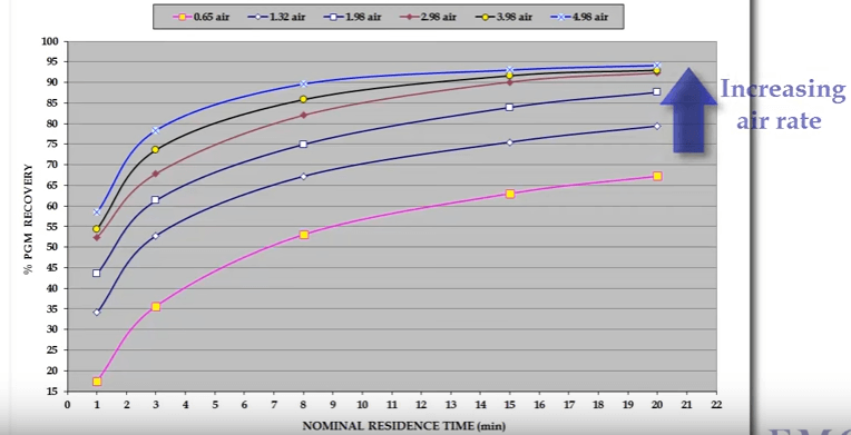 The graphs show platinum group metals as PGMs and gangue recovery with flotation time at six different air rates measured as cubic meters of air per minute per cubic meter of pulp. PGM concentrate mass recovery increase at different rates resulting in the system operating at successively different recovery grade curves.
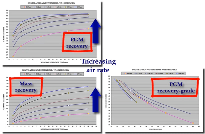 You can see that highest concentrate grade is generated at the lowest air rate but also for the lowest recovery. In other words, lowest aeration rate to generate the best selectivity between mineral and gangue.
These tests were conducted at a fairly high rotor speed of fifteen hundred RPM. If rotor speed is reduced, the same effect is achieved; that is selectivity increases as less air is introduced into the system.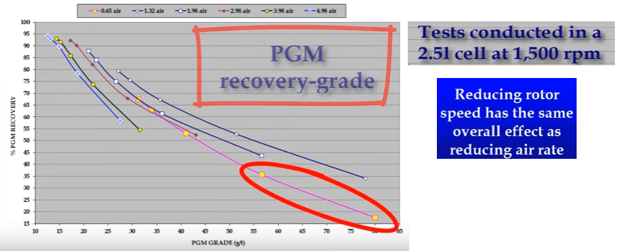 However in this case an extra variable is being added due to the smaller degree of agitation.
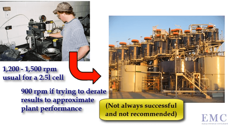
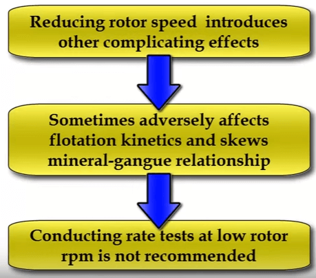 Some companies and operators prefer to run with a lower rotor speed such as nine hundred rpm in an effort to derate the laboratory cell so that its operation is closer to that of a production scale cell.
 These graphs illustrate that aeration rate changes flotation performance quite significantly.
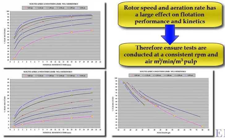 Whatever rotor speed and aeration rate is chosen for consistency make sure that all subsequent tests are performed at the same speed and air rate. The sample can be crushed and milled in the laboratory or it can be obtained from sampling the required stream in the plant.
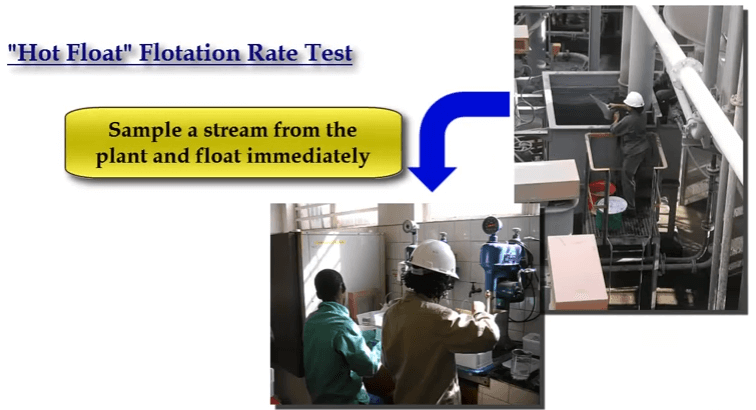
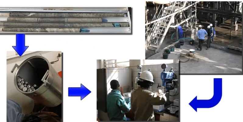 Rate testing a plant grab sample is often known as a hot float.
 For samples prepared in the metallurgical laboratory, all conditions of grinds, reagents, pH and % solids etc are chosen by the operator.
Hot floats are normally performed as is unless the intention is to add additional reagents or change pulp density and pH.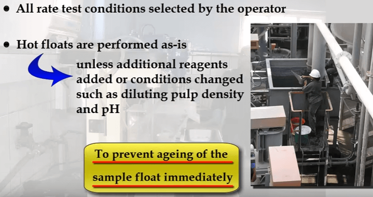 Note that to avoid ageing of the sample and possible oxidation effects, flotation should be done as soon as possible after sample collection. Auto-rotation speed of fifteen hundred RPM, add water until the pulp level is set at fifteen to twenty millimetres below cell overflow lip. The distance will be less at lower rotor speeds. Add and condition all reagents finally adding frother and begin the test by opening the air valve.
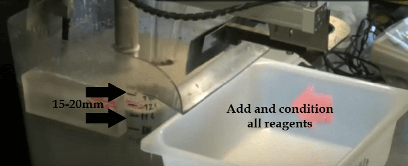 The aim throughout the test is to maintain the top of the froth bed, level with the overflow lip of the cell. As the test proceeds this is achieved by gradually opening the air valve.
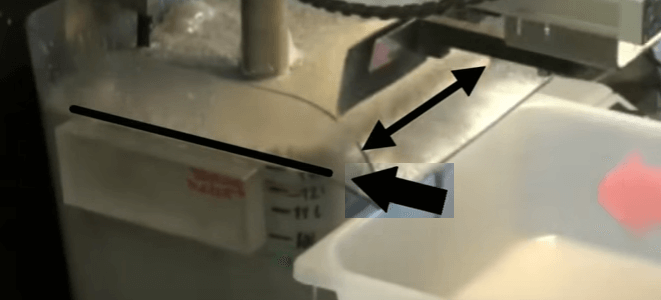 When fully opened, froth level is kept at the desired height by raising pub level with make-up water. By keeping the level of the froth consistently equal to that of the overflow lip, the quantity of froth removed is controlled by the paddle design and the number of froth removal sweeps per minute. Details of the number of concentrate collections per minute and timing of the sweeps can be found in EMC’s procedure.
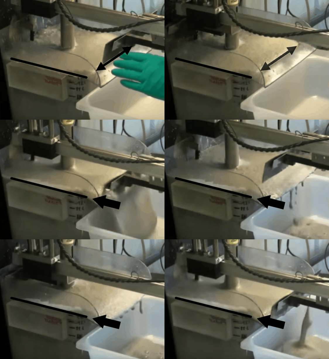
The video shows an automatic laboratory flotation cell developed by Outotec at their research centre in Pori in Finland. In this case the cell is 12 litres treating 3.5 kilograms of ore 25% solids. Rotor speed is 1500 RPM and air is fed at a rate of 5 LPM. The collection paddle is automated and set to collect froth every 10 seconds to a depth of about 10 millimetres below the overflow lip.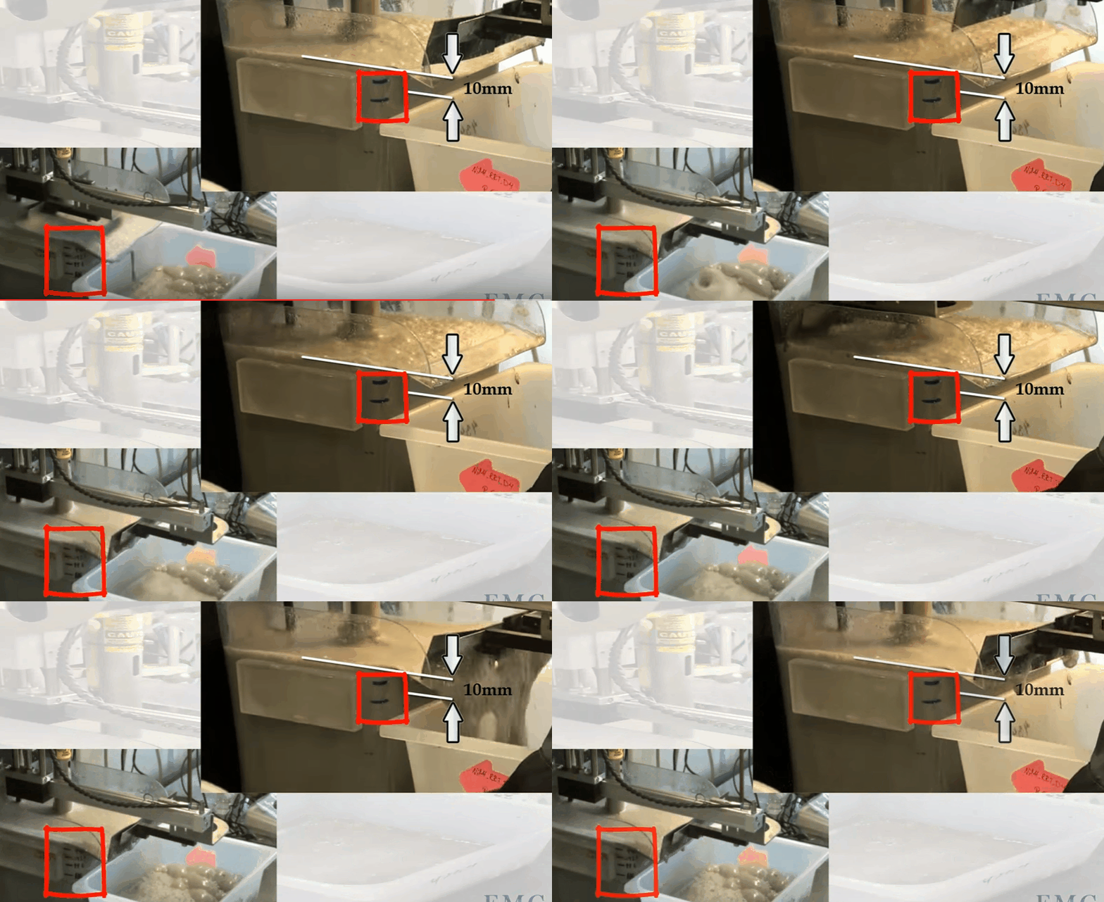 Know the level marks on the side of the cell; the top one being levelled with the overflow lip. Water is added to obtain the required pulp level. The paddle is split so that collection can be from the back of the cell and around the shaft as it moves forward. Paddle shaft and the sides of the cell are washed down with spray water. Level control is automated and both makeup and spray water masses used are recorded throughout the test.
This concludes the overview of the important features of a flotation rate test. View the next video on the meaning and use of kinetics to find out more about or characterization and flotation circuit design.
Mineralogy & Flotation: Floatability VS Selectivity Test Assessment
Flotation Kinetics: Mass & Water Recovery VS Entrainment & Mineralogy
Timed Flotation Test: Concentrate Collection & Cumulative Grade Recovery Curve
Laboratory Flotation Test Procedure
