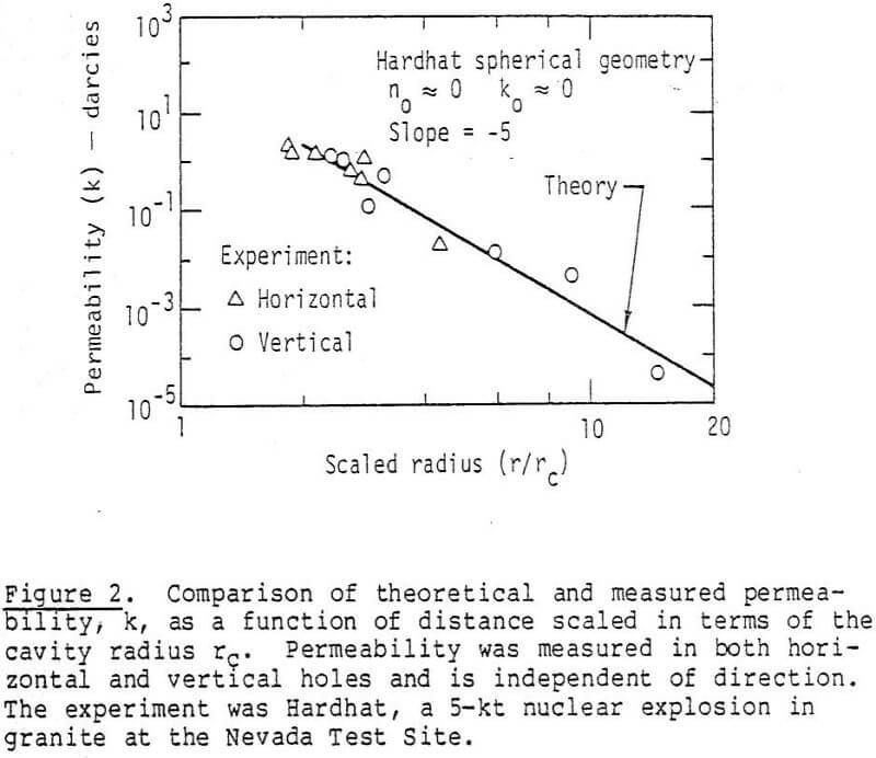
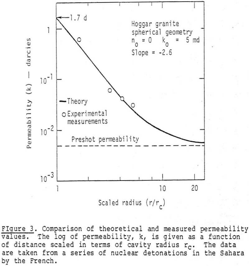
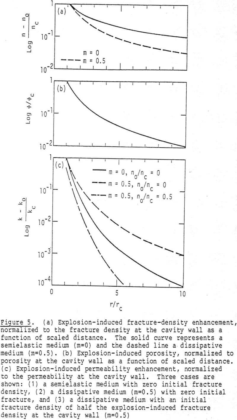
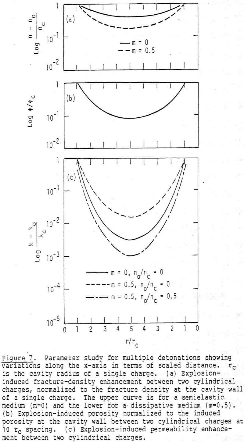
Explosive Selection to Maximize Permeability Enhancement: As can be seen from the previous sections the single most important scaling parameter is the postshot cavity radius or sprung hole diameter. From Figures 5 and 7 it can be seen that permeability enhancement is considerably diminished at a distance of 6-10 rc from the center of the hole. Accordingly, the larger the postshot cavity radius rc, the greater will be the distance over which the permeability is enhanced. This leads us naturally into the question of which explosive to use to produce the largest postshot cavity radius rc, and therefore the maximum extent of permeability enhancement.
Rock blasting and explosives are treated exhaustively in a number of articles and books. Virtualy all the applications are related to the proximity of a free surface. Reflection of the compressional stress from the free surface creates tensional stresses which spall the rock near the free surface and provide relief to enhance breakage. In-situ applications in which the explosive is deeply buried and hence far removed from a free surface have received little attention by comparison.
In formulating a model for explosively expanding the hole from its initial dimensions to a larger diameter we must first understand explosive properties in addition to the rock properties. Explosives are classified into two categories: ideal and nonideal. Ideal explosives are characterized by a rapid release of energy. The chemical reactions occur on a time scale which is small compared to the time required for gases to expand and the stress wave to propagate into the surrounding rock. Ideal explosives are generally a homogeneous material consisting of one component. TNT, nitromethane, and PETN fall into this category.
Nonideal explosives, on the other hand, require a much longer time to release their energy. Such explosives are multicomponent systems, with fuel and oxidizer usually occurring as fine particulates in physically separated phases.
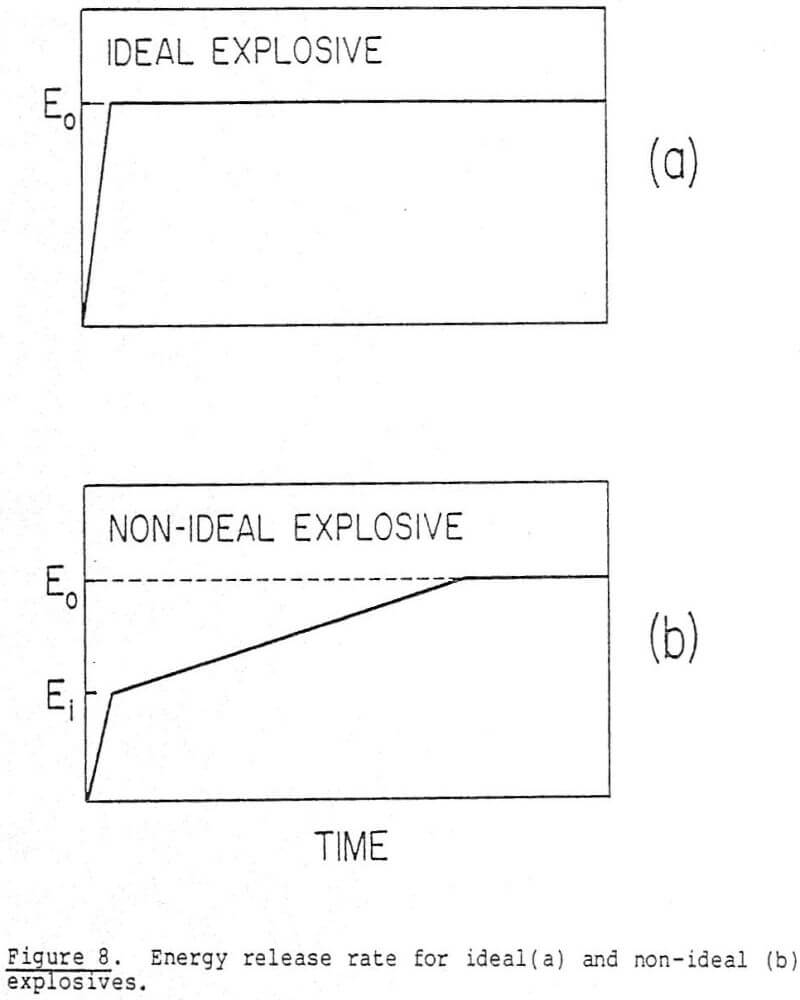
The detonation velocity for both ideal and nonideal explosives generally lies in the range of 0.5 to 1.0 cm/microsecond. However, the time for total chemical reaction may be on the order of a microsecond for an ideal explosive such as PETN. A nonideal explosive such as ANFO reacts totally in approximately 50-100 µs; the cavity is fully formed in about 3 milliseconds. Their energy content, E0, is released in a different manner, as illustrated in Figure 8. In Figure 8a (ideal explosive), all the energy is released in the time required for the detonation wave to transverse the explosive. The nonideal explosive releases an initial amount of energy as the detonation wave passes which is significantly less than the total content, as shown in Figure 8b. This has the effect of slowing the decline of pressure in the cavity so that it can perform more work against the rock and expand the hole to a larger radius. The slower rate of energy release also provides a better impedence match to the rock. It can also result in gas fracturing to appreciable distances from the cavity.
The rapid release of energy from an ideal explosive tends to be manifested in higher frequency components in the stress wave which attenuates rapidly by dissipating its energy in the production of fines. A slower release of energy results in a longer wavelength, greater energy acceptance by the rock, and production of more desirable block sizes.
In enlarging the hole or cavity from its initial dimensions to its final sprung radius, the explosive gases continue to expand until they reach equilibrium with their surroundings. This problem was first studied by Butkovich. He examined the output of extensive computer calculations and compared their productions with observed events from underground nuclear explosions. He found that the gases generated by the explosive expand to an equilibrium state which is determined by the overburden pressure (pgh) and the strength properties of the medium. The failure radius, extent of fracturing, and permeability enhancement were found to depend on the final cavity size, in agreement with our results. Several high explosives were compared by Butkovich with different detonation velocities and C-J pressures. He concluded that there was no significant difference in the failure radius due to these quantities; “The main characteristic of the explosive in terms of high explosive fracturing is the value of v/vo at the final cavity pressure.” v/vo is the volume expansion factor of the explosive, and hence the cavity, over its original specific volume vo.
The equation describing the adiabatic expansion of an explosive is the JWL expression

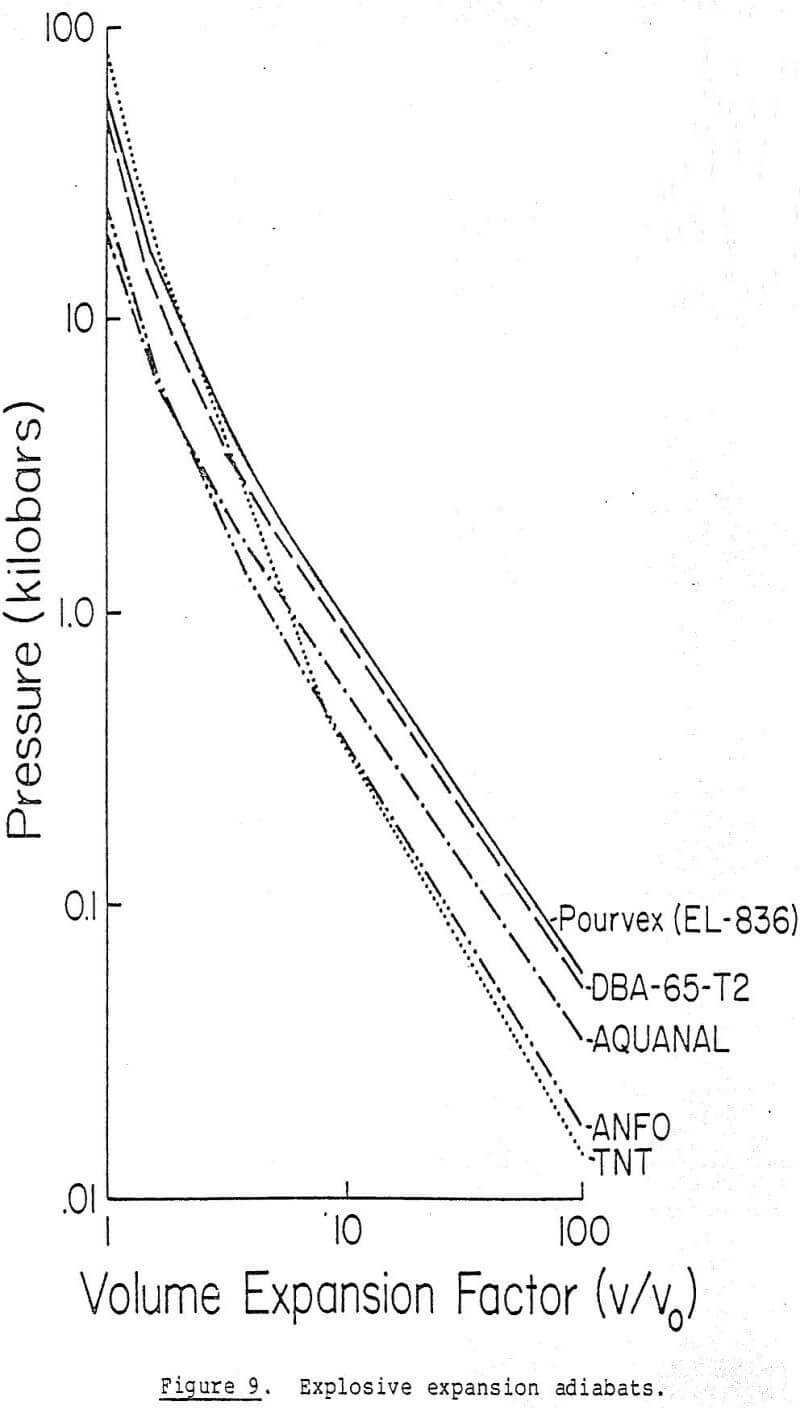
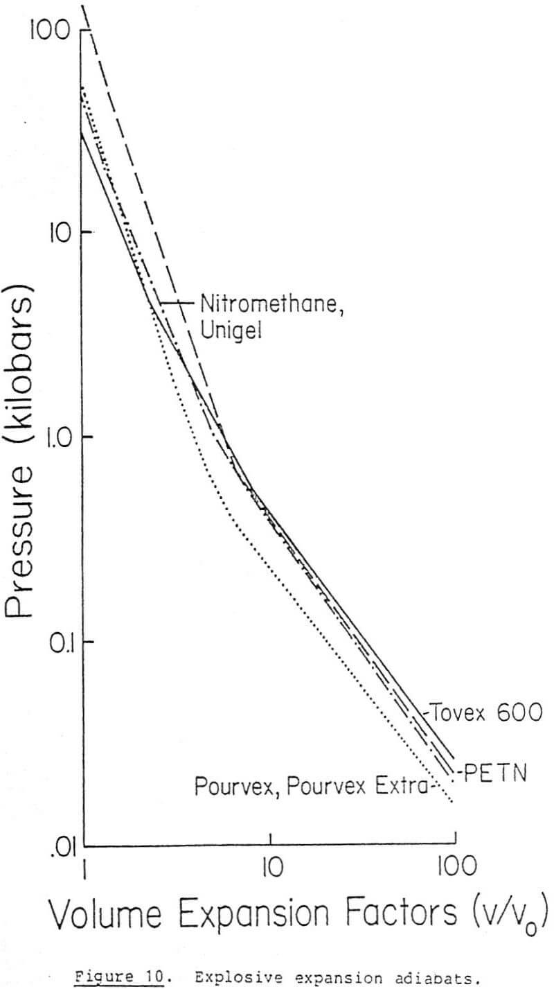
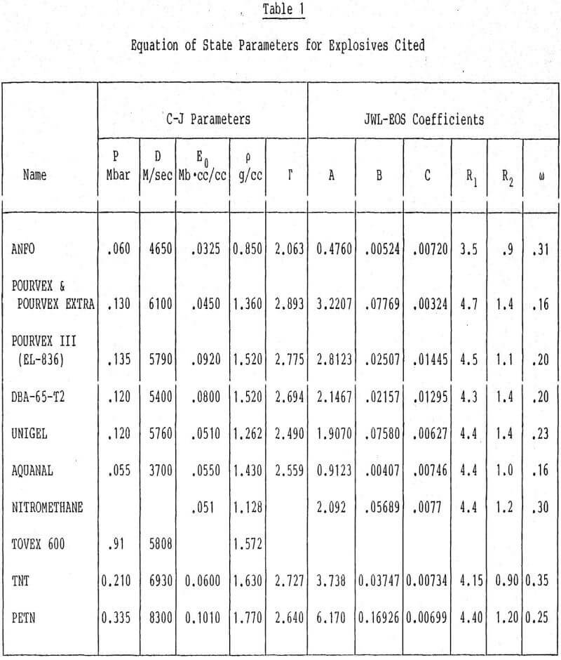
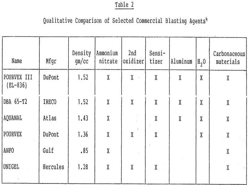
where Ps is the pressure under constant entropy or adiabatic conditions, V is the relative value v/vo, and the remaining constants are parameters appropriate to individual explosives. These parameters are listed in Table 1. The qualitative composition of some of the explosives is given in Table 2. Expansion adiabats for the explosives listed in Table 2 are graphed in Figures 9 and 10. The explosives in these figures which perform best are those that produce the largest volumetric expansion in the final cavity pressure range, which is generally below 1 kb (10 8 PA).
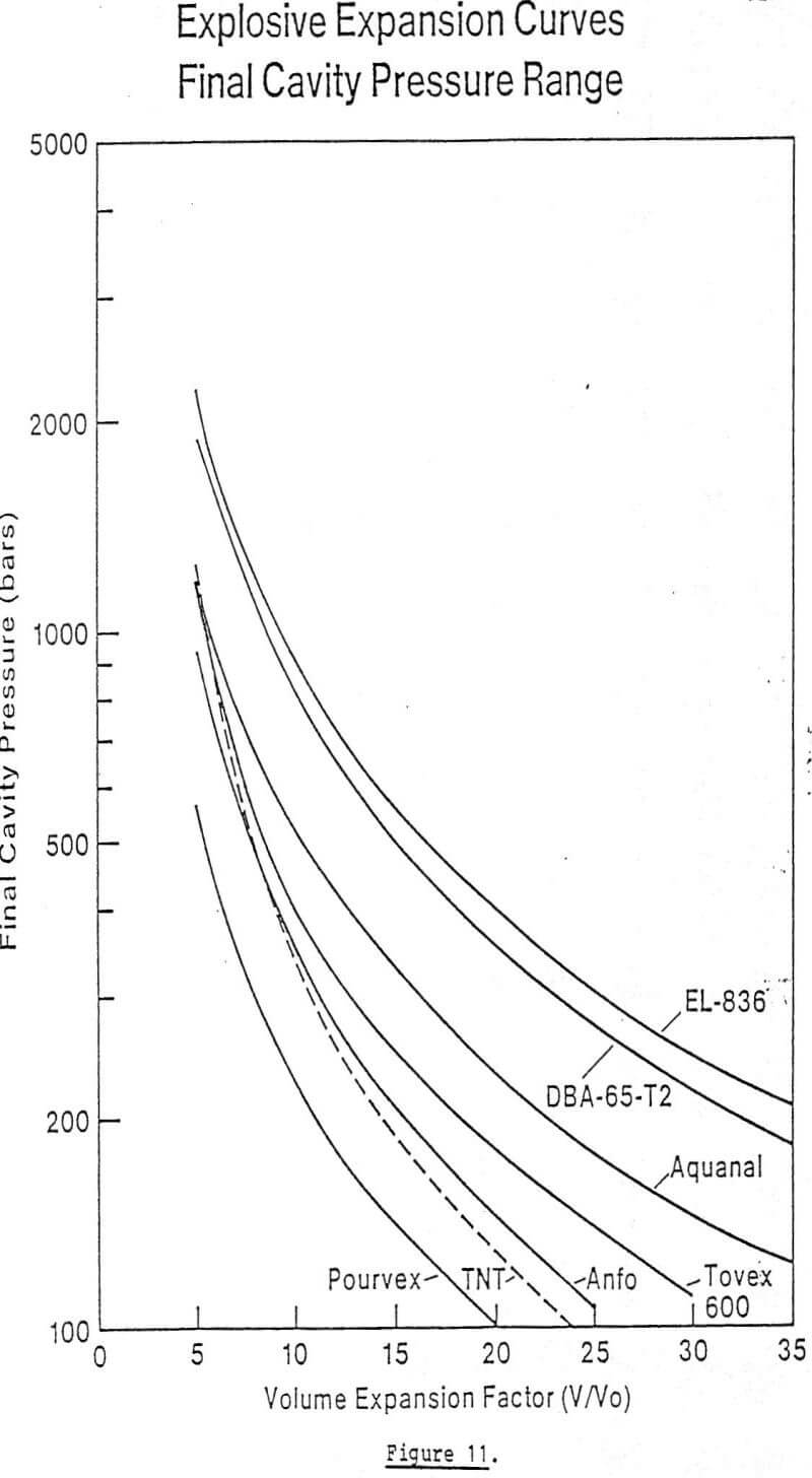
Examining the effectiveness of the explosives given in Figures 9 and 10 demonstrates that those with an ammonium nitrate base, added oxidizer, and aluminum performed best. These explosives have the highest density and energy content. While military-grade explosives such as TNT and PETN have higher initial pressures at v/v0 = 1, they lose their strength to expand the cavity in the critical range in comparison to DuPont’s EL-836 and IRECO’s DBA-65-T2. Figure 11 depicts the expansion curves in final cavity pressure range. The superiority of these two explosives is even more apparent.
For explosives in boreholes the initial (ro) and postshot hole radius (rc) are related by
rc = ro (v/vo)½……………………………..(6.2)
From the final cavity pressure Pf, the value v/vo is determined using Figure 12 and substituting into equation (6.2) . As previously discussed, the final explosive gas pressure at which the cavity stops growing is the sum of overburden pressure and some strength effect of the rock.
Butkovich did not quantify the strength effect term to enable prediction of pf from fundamental rock properties. This can be done by constructing a simplified model of the process, which we discuss below.
To obtain the final cavity pressure we assume the cavity growth ceases when the pressure exerted on the cavity wall falls just below the yield strength of the rock. An equilibrium solution for the stresses around a pressurized cavity gives for the stress

where σr = radial stress
σθ = tangential stress
P0b = overburden pressure
rc = cavity radius
r = distance from the center of the cavity
pc = final cavity pressure.
There are at least seven failure criteria which can be considered. The one most frequently used is that of maximum distortional strain energy, also known as the maximum octahedral shear stress criterion, which is attributed to Von Mises. For our use it has the form

where σo is the yield stress in uniaxial compression. This formula has been used by Scott and others to explain rupture around boreholes. Evaluating the stresses at r = rc yields
σr = Pc
σθ = 2Pob – Pc…………………………………(6.6)
Setting σz equal to the overburden pressure Pob, and substituting into equation (6.5) yields

where the second term on the right is the shear strength of the rock. The final cavity pressure at which expansion stops is therefore equal to the sum of the overburden pressure plus the shear strength of the rock. This is in general agreement with Bukovich’s findings discussed earlier. If the explosive’s expansion adiabat is represented by
![]()
where γ and c are determined for each explosive from Figure 11, then the cavity radius is given by the espression

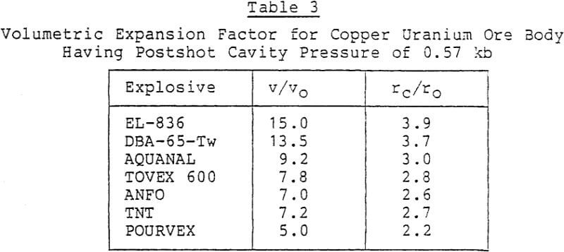
As an example, let us consider a copper/uranium ore body with an average compressive yield strength of 0.9 kb at a depth of 675 ft. If the overburden density is 1.1 gm/cc, then the overburden pressure is 0.05 kb. Substituting into equation (6.7) results in a final cavity pressure of 0.57 kb. Returning to Figure 11, we can find the volume expansion factor appropriate to each explosive (Table 3).
From Figures 5 and 7 the power law range for permeability decay will limit the spacing of explosives. Depending on kc (explosively created permeability at the cavity wall), and ko (initial permeability), the spacing of explosives can probably be no greater than ten to fifteen times the postshot cavity radius apart.
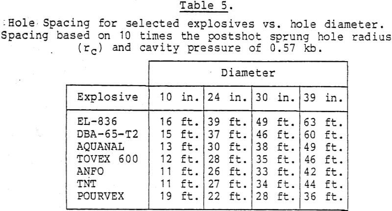
Presented with this fact, two alternatives are available. The first is to drill a large-diameter hole, in the range of 24-30 inches, with a drill such as the Ingersoll Superdrill. Or, one might drill a smaller hole approximately 10 inches in diameter and spring the hole to 3.25 feet (39 inches) in diameter using a high-energy explosive such as EL- 836, or an equivalent product. This could be followed by reloading with a less expensive ammonium nitrate water-gel type of explosive or ANFO if conditions permit. The follow-up step with ANFO would spring the cavity to 3.5 feet in diameter (rc = 4.25 feet). In view of the cost of EL-836 ($ 1.10/lb) vs. ANFO ($0.10/lb) the second approach may be more cost-effective. These two steps are correctly summarized in Tables 4 and 5, which give hole spacing for each type of explosive. This is based on a final cavity pressure of 0.57 kb from our previous example, and spacings
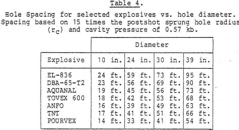
of 15rc and 10rc as a function of initial hole diameter. Table 4 shows spacings of up to 95 feet using the highest energy explosive, with typical spacings in the range of 40-60 feet. Table 5, based on 10 rc, is more conservative, with spacings of approximately 40 feet for the higher energy explosives. In each table the explosive bore holes must be loaded over a length which is approximately twice the well spacing, otherwise end effects are important and will reduce the spacing, the amount of reduction to be determined from more detailed calculations.
These calculations for the example problem demonstrate
(a) that explosives must be loaded in large-diameter boreholes created either by direct drilling or by initially drilling smaller holes which are sprung and then reloaded;
(b) that unless holes are sprung to larger dimensions and reloaded the practical well spacing is limited to between 40 and 60 feet.

While the data in the table relies on nuclear explosives, we recall from section 2 that the acceptance stress into the rock is comparable with chemical explosives. Permeability enhancement effects should therefore bear some similarities.
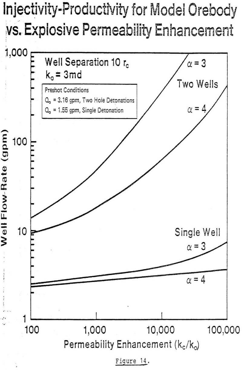
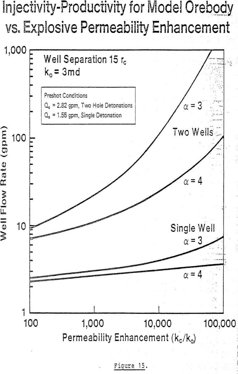
If these assumptions are acceptable, while recognizing the limitations of the data one could expect ratios of kc/ko in the range of 300 to several thousand. This implies that for the model ore body flow rates should be enhanced from ten gpm up to as much as 100 gpm. These rates are similar to those occurring in conventional permeable ore bodies in Texas and Wyoming and lend encouragement to the feasibility of in-situ mining of hard-rock ore bodies.
