Table of Contents
Commercial production of zinc by electrolysis began in 1881 following a patent by Letrange of France. The process has come down to the present day essentially unchanged and consists of three basic steps:
- Leaching of roasted zinc concentrates in dilute H2SO4; for example, ZnO + H2SO4 → ZnSO4 + H2O.
- Purification of the resulting zinc sulfate solution.
- Electrolysis to recover the metallic zinc as a high-purity product.
Only the high-hydrogen overvoltage on zinc permits the deposition of zinc at the cathode since thermodynamics favor decomposition of water and evolution of hydrogen.
The literature written on zinc electrolysis is voluminous; however, the complexity of the problem warrants further research.
Pure aluminum cathodes have been used since the inception of the zinc electrowinning process. However, the problem of deposited zinc sticking to the aluminum cathode has plagued the industry for many years; it causes metal losses and discourages automation. It is agreed generally that sticking is caused by fluoride ions in solution that attack and etch the aluminum cathode. Subsequent intergrowth of the zinc deposit into the pits and crevices results in mechanical interlocking, making stripping of the zinc deposit difficult, if not impossible.
Kelly found that both Cl- and F- contributed to sticking, with Cl- favoring greater sheet adherence and F- favoring spot adherence. There was no correlation between surface roughness and adherence. However, smaller aluminum crystals in the cathode surface favored stronger adherence.
Klimenko concluded that electrolytic deposition of zinc leads to a mechanical bond between zinc and aluminum crystals. The strength of the bond is determined by the state of corrosion of aluminum (degree of elimination of the surface film) and the microstructure of the adhering zinc. The corrosion state of aluminum was also found to be a direct function of the concentration of F- in the solution and the amount of time it is in contact with the uncovered cathode.
The work of Kammel and Saadat showed that Cl- and F- in the electrolyte, as well as higher temperatures, increase intensity of retention; however, using zinc cathodes for zinc electrowinning will solve this problem. Using zinc cathodes eliminates the necessity for stripping the zinc deposit from the aluminum cathode and enables the recovery of zinc by electrolysis of ZnSO4 solutions prepared from domestic concentrates and wastes containing fluorides. At the end of electrolysis, the all-zinc cathode is removed and melted in the furnace for casting.
Several investigators have attempted to use zinc cathodes for electrowinning zinc but had limited success because of solution-level corrosion that allowed the zinc cathode to drop off into the cell after a period of time.
Many procedures have been developed to eliminate or modify the effects solution-level corrosion.
Ware, Blake, and Higbie investigated the conditions necessary for making thick electrodeposits of zinc on zinc starting sheets to eliminate the stripping costs and reduce melting losses. They were able to produce zinc on zinc cathodes and avoid solution-level corrosion by rigorous purification of cell-feed solutions and by using specially designed cathodes. In fact, the cathode was suspended completely below the level of the solution by a shank that was large enough in cross-sectional area to withstand solution-level attack.
Ralston has shown that solution-level corrosion can be successfully prevented by applying a protective coating at the solution level or by progressively lowering the level of the electrolyte in the cell.
All of the methods described have proved to be impractical, expensive, and commercially unacceptable.
During the course of this investigation, the reason for solution-level corrosion was determined, and a practical, inexpensive, and effective method was devised to prevent it. Solving the problem of solution-level corrosion of the zinc cathode cleared the way for demonstrating that zinc cathodes can be used for electrowinning zinc from solutions containing fluoride ion.
Experimental Procedure
Materials and Equipment
All electrolyses were performed with constant current using a 40-volt, 50-amp direct current power supply.
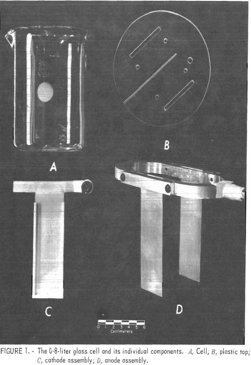
Glass 0.8-, 1-, 5-, and 10-liter cells were used initially with a plastic top of sufficient thickness to hold and space the electrodes and to reduce the amount of solution evaporation. Later, plastic cells were substituted for the glass cells when working with solutions containing fluoride ion. The plastic top had a 0.08-cm-wide slot cut so that the cathode could be slid in from one edge and be centered in the cell. Precisely 3.8 cm on each side of the cathode and parallel to it, two openings were cut to the appropriate width for inserting the anodes. Figure 1 depicts the 0.8-liter glass cell and its individual components. The temperature of the 0.8-, 1-, and 5-liter cells was controlled at 35° to 40° C by using a hot plate with thermistor control. However, with the 10-liter cell, it was necessary to cool the cell slightly to maintain the electrolyte temperature in the 35° to 40° C range. Cooling was accomplished by wrapping the cell with a copper coil and passing water through the coil.
Table 1 shows the cell size and dimensions of anodes and cathodes used.
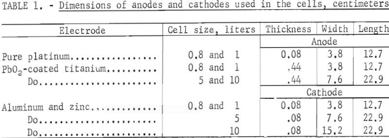
The Bureau of Mines developed the PbO2-coated titanium anodes that were used in these experiments. All cathodes were made from purchased 1100 alloy aluminum sheet or zinc sheet from 99.9 pct pure zinc stock that was warm-rolled at 250° C on an 8-inch wide laboratory rolling mill.
The platinum anodes were bolted to an elliptical shaped, pure (99,99 pct) aluminum ring that held them 7.6 cm apart and parallel to each other (fig. 1). Similarly, the PbO2-coated titanium anodes were welded to a titanium ring for use in the 0.8-, 1-, and 5-liter cells. A banana plug was mounted in the center of one end of the ring for the electrical connection, and the end of the plug was wrapped tightly with Teflon tape to prevent accidental contamination of the solution by corrosion products from the brass on the plug inadvertently getting into the cell.
The aluminum and zinc cathodes used in the 0.8-, 1-, and 5-liter cells were cut T-shaped (fig. 1C). When the cathodes were inserted into the slot in the plastic top, the arms of the T were bent in opposite directions to hold them in place. A banana plug was attached to one arm of the T for the electrical connection, and the end of the plug was wrapped in Teflon tape.
The anodes and cathodes used in the 10-liter cell were bolted to a 0.6- by 2.5-cm aluminum bus bar that stretched across the top of the cell; banana plugs were again used for the electrical connections.
Teflon strips, 0.3 cm thick by 0.6 cm wide with a 0.08-cm slot in the center, were placed on the edges and at the bottom of the aluminum cathodes to minimize current concentration and the resulting dendritic growth in these areas.
The cathodes were sanded with 600-grit emery paper, to remove the rolled-surface, then washed with distilled water and blotted dry before being placed in the cell. Anodes also were washed with distilled water and dried before using.
Electrolyte Preparation
Neutral zinc sulfate solution was prepared by dissolving stoichiometric amounts of lead-free photoconductive zinc oxide or zinc calcine in reagent-grade sulfuric acid and distilled water. The solution then was purified by the standard commercial practice of oxidation with MnO2 to precipitate ferric hydroxide (iron purification), followed by two successive treatments with zinc dust (copper -cadmium purification). Purified neutral solution, concentrated H2SO4, and distilled water were mixed to give a cell solution with a nominal concentration of 65 g/l Zn++ and 200 g/l free acid.
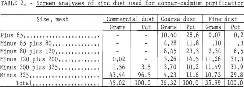
The zinc dust used for purification in the initial experiments was purchased from a commercial chemical supplier. Later, the particle size of the dust was found to have an important bearing on the degree of purification obtained, therefore, coarse- and fine-mesh dust were obtained from a zinc electrowinning plant. (Table 2 gives the screen analyses of these dusts.)
Zinc concentrates containing 58 pct Zn -30 pct S, and 0.5 pct F- as CaF3 were obtained from Illinois for the final phase of this work. Standard commercial practice is to roast in fluid-bed roasters at 930° to 950° C, and the sulfur content is usually reduced to less than 1 pct. A great deal of difficulty was experienced in roasting the sample because a fluid-bed furnace was unavailable. Eventually the material was roasted using a fire-clay crucible in a pot furnace a 1,200° C for approximately 24 hours. An air lance was placed near the bottom of the crucible to aid in oxidation and sulfur removal. The sulfur content of the charge was lowered to -2 pct. Unfortunately, the fluoride concentration was reduced to 0.02 pct owing to the high temperature and long roasting time required to remove the sulfur.
The calcined material was leached with H2SO4, purified by oxidation, and treated with zinc dust. The presence of deleterious amounts of impurities remaining in the electrolyte after purification resulted in a modification of the purification procedure. The method finally adopted for purifying the neutral zinc sulfate solution with zinc dust was as follows:
- Add 1.96 g/l CuSO4·5H2O.
- Add 0.08 g/l As2O3.
- Heat to 85°-90° C, add 3.0 g/l coarse zinc dust, hold for 2 hours at temperature.
- Add 0.5-g/l coarse zinc dust at ½-hour intervals during the 2-hour holding period.
- Filter the hot solution through two thicknesses of filter paper.
- Repeat steps 3 through 5 using fine zinc dust.
Operating the Electrolytic Cell
The clean, dry cell was filled with a solution containing 65 g/l Zn++ and 200 g/l H2SO4, and the temperature was allowed to stabilize between 35° and 40° C. A magnetic stirrer was activated to spin a Teflon-covered magnet for stirring the solution.
The cathode, with the Teflon edge strips in place, was inserted into the slot in the plastic top and slid into the center. The anodes then were placed through the slots on both sides of the cathode, and the entire assembly was flushed with distilled H2O and blotted dry. Leads from the power supply were attached, the electrodes were placed into the cell, and the power supply was turned to the desired current setting immediately.
As soon as the power was on, plastic tubing from a peristaltic pump was fitted into a small hole in the plastic top in back of one of the anodes, and neutral solution was pumped from a reservoir into the bottom of the cell. Simultaneously, and at the same rate, cell solution was pumped out at the top of the cell. Constant zinc ion and sulfuric acid concentrations were maintained in the electrolytic cell by varying the pumping rate.
After completing electrolysis, the cathode was removed as rapidly as possible and flushed with distilled water. A handheld dryer was used to rapidly dry the cathode to prevent discoloration or staining. Once the deposit was completely dry, it was stripped from the aluminum by flexing. With some deposits that were strongly adherent, a knife or razor blade was inserted under one edge to pry them loose.
Analysis and Evaluation
An aliquot portion of electrolyte was pipetted periodically and titrated against 1N NaOH, using a methyl orange indicator to determine the H2O04 concentration.
The amount of zinc in the neutral zinc sulfate solution was determined by the following procedure:
- Mix a 0.5-ml aliquot of the neutral solution with 100 ml of distilled H2O.
- Add 5 ml of pH 10 buffer solution. (For the cell solutions containing less zinc, it was necessary to raise the pH to -6 with 1N NaOH prior to adding the buffer solution.)
- Titrate with 0.1M EDTA solution, using Eriochrome Black T indicator to a blue end point. (The concentration of zinc in the solution then was calculated in the usual manner; for example, ml1·N1 = ml2·N2.)
Current efficiency was calculated by comparing the actual weight of the zinc deposit with the theoretical weight. Selected deposits were examined on the scanning electron microscope (SEM) and the electron microprobe, and photographs were taken of typical structures.
Results and Discussion
Preliminary Work Using Reagent-Grade ZnO
Several tests were made with pure platinum anodes and an aluminum cathode to determine the quality of purified solutions prepared from reagent-grade ZnO and H2SO4 and to familiarize personnel with procedures used for zinc electrowinning. Good deposits were obtained with -92-pct current efficiency at 8 amp/dm² and 35° C from a solution containing 65 g/l Zn++ and 200 g/l H2SO4. Deposit morphology was excellent, although some pitting began to occur after 6 hours.
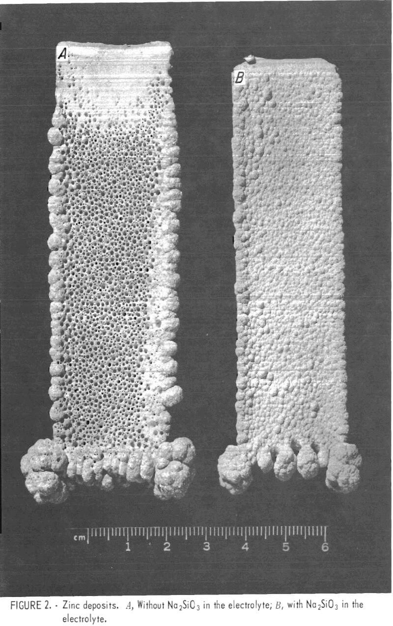
In an attempt to eliminate the pitting, small amounts of sodium silicate (Na2SiO3) were added to the electrolyte prior to electrolysis. Adding Na2SiO3 resulted in a marked improvement in the morphology of the zinc deposit, but an excess tended to reduce current efficiency. For example, 100 mg/l of Na2SiO3 reduced the current efficiency from a nominal 90 pct to less than 10 pct. The optimum amount of Na2SiO3 to eliminate most of the pitting, without a reduction in current efficiency, was found to be 25 to 35 mg/l (fig. 2).
The mesh size of the zinc dust used for copper-cadmium purification was also found to have an effect on pitting of the zinc deposit. A very fine dust (96.5 pct minus 325 mesh) had been used for both purifications. At least one domestic smelter uses a coarse-mesh zinc dust for the first purification, in which copper sulfate and arsenic trioxide are added, and a fine-mesh dust for the final purification. It had been suspected that the rapid dissolution of the fine dust resulted in incomplete purification. Evidently, the coarse dust dissolves more slowly when added to the impure zinc sulfate solution and is, therefore, more effective.
Using coarse- and fine-mesh dusts (table 1) from a smelter to purify the solution, a pit-free deposit was obtained at 8 amp/dm² for 24 hours. However, a second deposit made in the same electrolyte was badly pitted. Additions of Na2SiO3 did little to eliminate this pitting.
The one difference between our electrolytic procedure and the usual commercial practice appeared to be related to the rate of solution flow through the cell. In a commercial cell, there are several complete solution changes per 24-hour period, whereas in our 1-liter cell, the solution flow was adjusted to maintain the zinc ion concentration constant and less than one complete solution change occurred in 24 hours. This suggested that there was an impurity buildup in the cell. To test this theory, the cell size was
reduced to 0.8-liter. Since the current density and cathode size remained constant, the smaller cell volume allowed a faster rate of solution change, which negated impurity buildup. Consequently, the second and third successive 24-hour deposits were found to be as good as the first. The current efficiency for all deposits was >93 pct, and the morphology was excellent.
Work With Fluoride-Containing Zinc Concentrates
Purification
Electrolysis of the purified solution prepared from the material roasted in a pot furnace failed to produce a deposit. The zinc went back into the solution faster than it would plate-out on the aluminum cathode. Analysis of the solution revealed the presence of cobalt and nickel in the range of 3 to 4 ppm. Commercial plant experience suggests that the cobalt concentration should not exceed 0.05 ppm; if this limit is met, the nickel concentration also will not exceed 0.05 ppm.
Additional zinc dust purification, using our normal procedure of holding 15 min at 90° C after adding zinc dust but before filtration, only decreased the concentration of cobalt and nickel to the 1- to 2-ppm range. The laboratory purification procedure was based on filtering the solution as rapidly as possible after adding the zinc dust, to avoid the tendency for impurities already cemented-out to redissolve.
By comparison, commercial practice is to perform the zinc-dust purification in a series of large tanks over a period of several hours. Therefore, it appeared that the current problem was one of incomplete purification due to insufficient reaction time, rather than one of impurities reentering the solution after they had been cemented-out.
When holding times were increased during the purification process, zinc deposits were produced repeatedly on both aluminum and zinc cathodes with good current efficiencies (-94 pct). Using the purification method described in the Experimental Procedure section under Electrolyte Preparation, the cobalt and nickel concentrations in the electrolyte were reduced below the target value of 0.05 ppm.
Re-solution
Although excellent deposits were obtained in 12-hour runs with current efficiencies exceeding 90 pct, the deposits began to redissolve after approximately 18 hours of electrolysis. Some current efficiencies were less than 50 pct. Since the cobalt and nickel concentrations had been reduced to very low levels, other reasons for re-solution were examined.
The accepted explanation for re-solution is that impurities are responsible. Low-overvoltage impurities, such as Cu, As, Sb, Ge, and Te, depositing with the zinc on the cathode would have a twofold effect; they would tend to lower the hydrogen overvoltage for zinc deposition and at the same time induce corrosion of the zinc through the action of local cells.
It was noted that usually zinc would deposit on the edges and bottom of the cathode at the areas of high current density and then the remaining V-shaped area would fill in. Re-solution usually occurred in reverse to deposition.
It first appeared as a black crescent-shaped area at the top of the cathode; sometimes it appeared mainly at the edges, depending on the nature of the impurity involved. As re-solution progressed, it was accompanied by evolution of hydrogen, which increased in inverse proportion to the amount of zinc deposited until no zinc remained on the aluminum cathode and only hydrogen was evolved.
Samples were taken from the top of a deposit after re-solution had started and from the center of the same deposit outside the re-solution area. The samples were examined on the SEM. (Fig. 3 includes micrographs of the representative structure.)
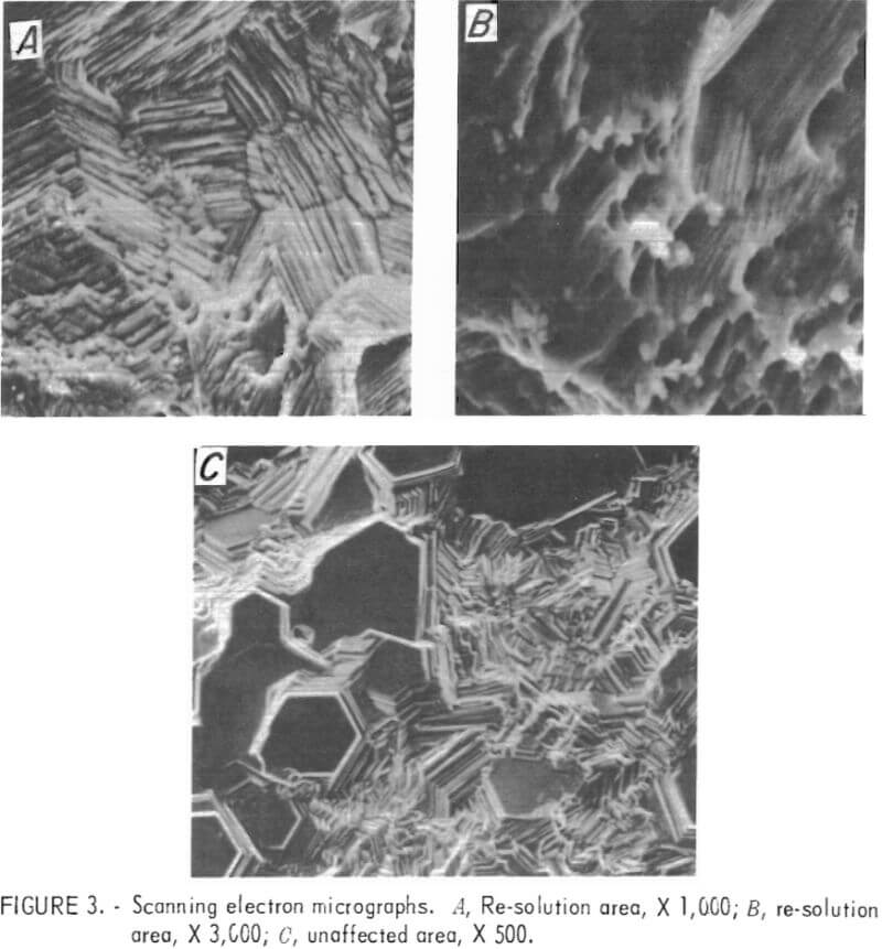
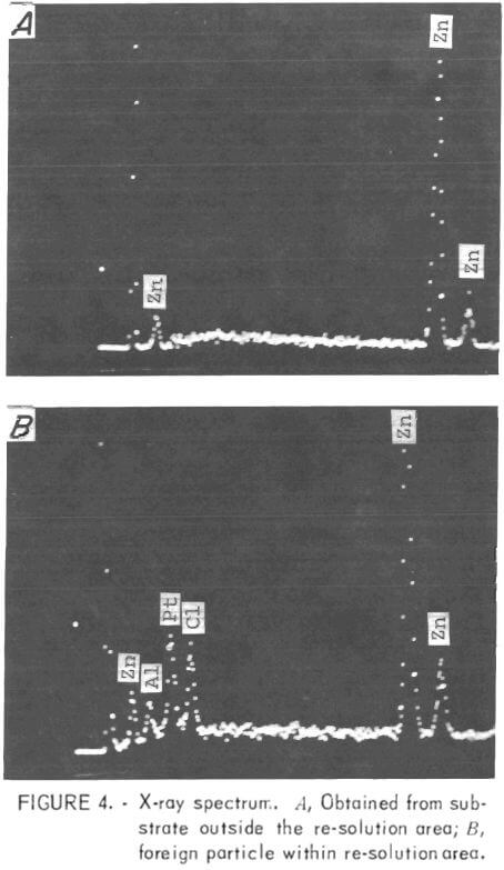 Note that the structure of the deposit from the area where no solution took place is composed of many basal planes with (002) orientation, but there are no basal planes visible in the re-solution area at the top of the cathode. In addition to the difference in morphology, the surface of the deposit in the re-solution area contained small foreign particles of approximately 2 to 4 µm scattered throughout.
The SEM nondispersive X-ray analysis system was utilized to identify the foreign particles seen on the zinc surface in the re-solution area at the top of the cathode. An X-ray spectrum was obtained on the base metal (zinc) and also on the small, white, -3.5-µm saltlike particle that can be seen in the center of fig. 3B. Three extraneous peaks were identified (left to right in fig. 4) as Al, Pt, and Cl. This analysis was the first direct evidence that platinum was present on the zinc deposit, although there was a great deal of indirect evidence to support this view, for example, very minor weight losses for the anode after long periods of time.
Previously, the microprobe had been used in an attempt to detect platinum, but without success. On the strength of the foregoing results, the same specimen was examined on the microprobe, and, again, no platinum was detected. The detector then was set for platinum and moved slowly over the surface. Platinum was found to be present in finely divided form throughout the re-solution area.
The presence of chlorine also was confirmed; therefore, it can be assumed that the platinum might have reached the cathode as a platinum-chlorine compound. Also, chlorine might have contributed to the dissolution of the platinum anodes. Aluminum was not found during the microprobe examination; it appeared that the presence of aluminum in the X-ray spectrum was due to scatter from the specimen holder, a problem that had been encountered on other occasions.
In light of the above evidence, the platinum anodes were replaced with PbO2-coated titanium anodes and the re-solution problem was eliminated. The platinum anodes had been used in the preliminary work assuming that their stability would eliminate one of the variables during determination of the operating parameters for the cell.
Fluoride Concentration
Results of chemical analyses had indicated that most of the fluoride had been removed from the concentrates owing to the excessive temperature required for the crucible roast. It was necessary to add fluoride to the electrolyte to cause the zinc to stick to the aluminum cathode.
Successive additions of F- (as 50-pct HF solution) in increments of 0.055 g/l were made to the zinc sulfate solution to determine the maximum tolerable fluoride level that would not impede stripping the zinc from the aluminum cathode. The zinc deposit became increasingly more difficult to strip as the amount of fluoride ions increased, and stripping was impossible when the fluoride level reached 0.55 g/l F.
The work to show that zinc cathodes could replace aluminum to win zinc from solutions containing fluorides was initiated in a 5-liter cell using the same solutions, temperature, and current density as employed for the aluminum cathodes except 0.55 g/l F- was added to the electrolyte. Zinc was successfully deposited on rolled-zinc cathodes at -92 pct current efficiency. The deposits were of fair quality, but they contained some pitting.
Solution-Level Corrosion
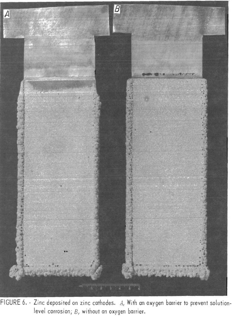
 Corrosion of the zinc starting sheet at the solution level was quite evident as anticipated. Deposits of zinc on zinc were made for 24 hours without separation of the cathode at the solution line, but dissolution was severe enough that it is doubtful whether electrolysis could have been continued much longer than 24 hours.
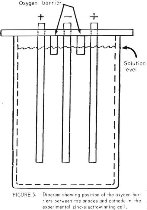
Close observation of the cell during electrowinning revealed that the phenomenon of solution-level corrosion was due to oxidation of the zinc at the solution line by oxygen from the anode. The problem was solved inexpensively by placing noncorroding strips between the cathode and the anode, which extended below the solution level (fig. 5) to act as a barrier to oxygen transport from the anode. The strips could be placed as a permanent fixture on top of the cell and should never require removal or replacing.
Figure 6 shows two zinc deposits made on zinc cathode starting sheets with -92 pct current efficiency. The zinc deposit on the left, made with oxygen barriers in place during electrolysis, shows no deterioration of the zinc starting sheet at the solution line. The zinc deposit on the right, made without the oxygen barriers, shows several holes at the solution line resulting from severe solution-level attack of the zinc starting sheet.
Final Test With a 10-Liter Cell
Tests were made in a 10-liter cell to obtain results directly translatable to commercial cell practice.
To bypass the roasting problems and facilitate completing the test, neutral purified solution was obtained from an electrolytic zinc plant in Sauget, 111., and fluoride was added to simulate the fluoride- containing zinc concentrates. This material already contained cobalt and nickel and was similar to solutions derived from the concentrates except for the lack of fluoride.
Final tests were made using a 10-liter plastic cell and aluminum and zinc cathodes with an effective working area of approximately 15 by 18 cm per side. Cell solution was prepared, as before, by mixing neutral purified solution, reagent-grade H2SO4, and distilled H2O. Approximately 8 mg/l of flake glue was added to the electrolyte to smooth the deposit.
Zinc was successfully deposited on aluminum and zinc cathodes from solutions containing enough fluoride (0.55 gpl F-) to cause sticking of the zinc deposit to the aluminum cathode. Solution concentration, current density, temperature, etc., were the same as for the small-scale test in the 0.8- and 1-liter cells.
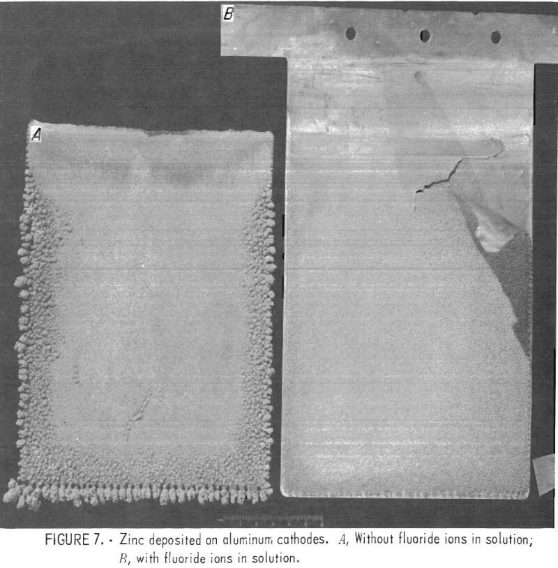
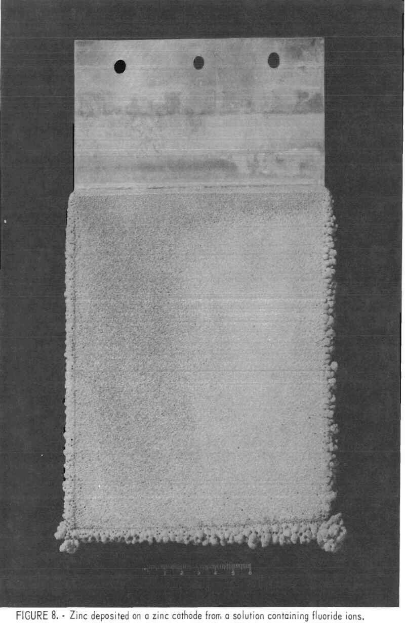
Current efficiencies were low, 82 to 86 pct, but normal for an electrolyte with impurities such as cobalt and nickel in solution. Morphologies of all deposits were excellent (figs. 7-8).
In fig. 7, the deposit on the left was on an aluminum cathode with no fluoride in solution. No difficulty was experienced with stripping this deposit. The deposit on the right was from a solution containing ~0.5 g/1 F-. Part of the deposit has been torn from the aluminum cathode indicating the effect of fluoride on strippability.
Figure 8 shows a deposit made in the same solution and under the same conditions as the deposit on the right in fig. 7; a zinc cathode was used along with oxygen barriers to eliminate solution-level corrosion.
Conclusions
A simple and inexpensive method was invented for eliminating solution-level corrosion of electrolytic zinc deposits. This invention enabled the development of a procedure for using zinc cathodes for zinc electrowinning, which, in turn, permits the electrowinning of zinc from solutions containing fluoride ion.
Over the years, the electrolytic zinc industry has been plagued with the problem of zinc sticking to aluminum cathodes, causing not only a loss of deposited zinc but, in some cases, a loss of the aluminum cathodes as well. Using zinc cathodes would not only eliminate sticking but also would enable processing of concentrates containing fluorides, encourage automation, and eliminate the edge strips now used to facilitate the stripping of zinc deposits from aluminum starting sheets.
The Bureau of Mines developed a procedure that enables substitution of zinc cathodes for the aluminum cathodes normally used in commercial zinc electrowinning. Using zinc cathodes eliminates the necessity for stripping and makes it possible to electrowin zinc from solutions derived from material containing excessive amounts of soluble fluorides; for example, zinc concentrates obtained as a byproduct of fluorspar mining in Kentucky and Illinois. To demonstrate the viability of using zinc cathodes, fluoride-containing zinc concentrate was roasted, leached, and purified according to current commercial practice. Electrolysis was carried out in 0.8-, 1-, 5-, and 10-liter cells at 35° to 40° C with a cathode-current density of 8 amp/dm² in a solution containing 65 g/l Zn++ and 200 g/l H2SO4 using PbO2 anodes. Zinc deposits were produced on zinc cathodes with good morphology and excellent current efficiency (90 to 94 pct) in solutions containing enough fluoride (-0.5 g/l, F-) to cause sticking of zinc to aluminum cathodes. The approach described has failed previously because of severe solution-level corrosion of the zinc cathodes. The present investigation found that the use of a simple mechanical barrier to prevent oxygen migration from the anode was sufficient to prevent solution-level corrosion of the zinc cathode starting sheet.
