Table of Contents
The object of this research was to investigate procedures for recovering copper from chloride solutions as part of a larger program involving the application of chlorination techniques to copper and other base metal sulfide concentrates. In the first step of the process, a pelletized chalcopyrite concentrate is chlorinated in a vertical shaft countercurrent chlorinator. Molten copper and iron chlorides run down while the sulfur evolved rises above the bed, is condensed, and recovered in elemental form. In a second step, the chlorinated mineral is pulverized and reacted with oxygen at 500° to 900° C during free fall in a vertical shaft reactor. Iron chloride is converted to oxide, and copper chloride emerges unoxidized. A chlorine-rich offgas is generated for chlorine recovery and recycle. The chlorinated and oxidized product is then leached with a recycled brine electrolyte and filtered to yield a concentrated copper solution for electrolysis.
The requirement of recovering elemental chlorine rules out methods of precipitating copper chlorides for eventual thermal reduction or direct reduction from solution with hydrogen in an autoclave. Electrwinning, on the other hand, provides recovery of chlorine and avoids troublesome byproducts.
Copper chloride electrolysis has been previously investigated by Kern in 1909. Ashcroft mentions a copper chloride electrolysis process of Hoepfner dating from 1887. More recently, Gokhale has investigated the effects of concentrations, stirring, and additives on cuprous chloride electrolysis. The recent tightening of pollution control regulations has given rise to a number of chloride hydrometaliurgical approaches. These either use electrolysis directly or suggest it as an alternative for copper reduction from copper chloride.
Recently, copper chloride electrolysis has been an integral part of a Bureau of Mines effort to study various chlorination methods for the recovery of copper and other base metals from sulfide concentrates. Consequently, varieties of electrolytic feed solutions are studied containing different impurities, wastes, and reactants. Thus far, a Bureau study successfully electrowon copper from a cuprous-ferric chloride solution produced by chloridizing leach of chalcopyrite concentrate in an aqueous solution. In this investigation, a similar treatment is described for the chlorination of chalcopyrite concentrate with chlorine gas- To make this treatment economically attractive, the chlorine gas is collected from the cell and recycled.
Experimental Equipment
The experimental electrowinning cell was a 20- by 15- by 15-cm plexiglass container as shown in figures 1-3. A funneled section projected under the
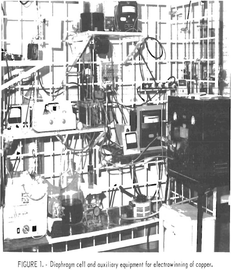
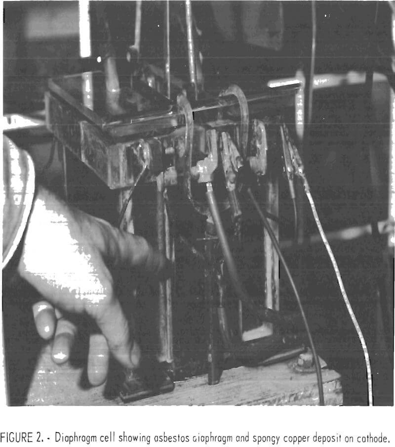
cathode to deliver falling copper powder through a short section of 25-mm rubber tubing into a removable holding flask below. Diaphragms were mounted on plexiglass frames that were inserted in slots in the cell walls. The diaphragms were submerged, but the frames extended to the top of the cell to wall off the anode compartments for chlorine recovery. Vented cover plates and attached tubes provided for the isolation and delivery of chlorine gas from the anode compartments. The insoluble anodes, which protruded through and were suspended by the side walls, were 0.95-cm-thick graphite plates with 400-cm² effective area. The cathode was positioned between the anodes with a spacing of 5 cm and consisted of a sheet of titanium with a 345-cm² effective area for copper deposition. The cathode was suspended from an eccentric shaft and could be mechanically shaken at timed intervals of 10 to 20 min or operated without shaking. When shaken, the vertical displacement amounted to 0.65 cm with a frequency of 5 c/sec.
Circulation of the electrolyte was provided by pumping 1 ½ liters of electrolyte per minute out one end of the cathode compartment and back through a six-hole multiple inlet in the opposite end. Electrolyte circulated around
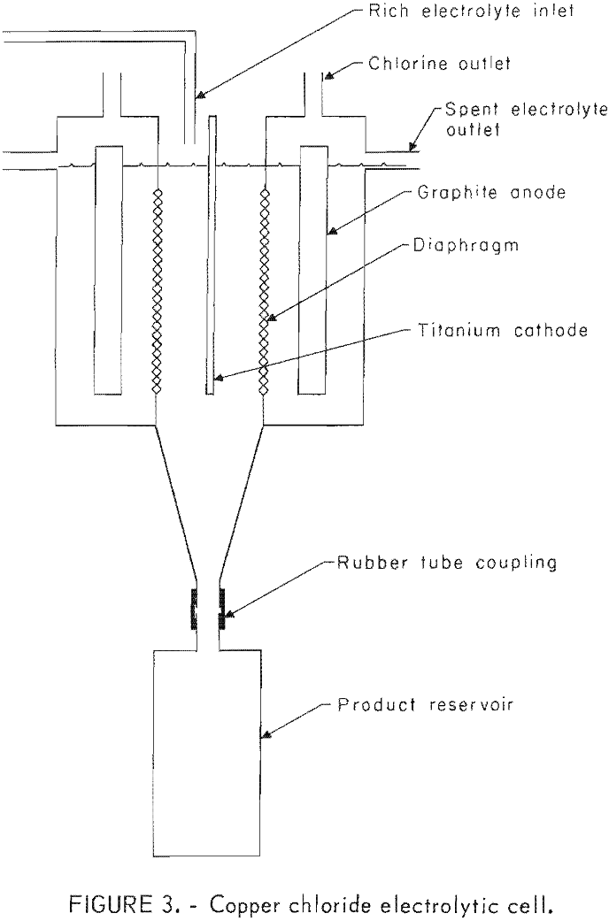
the cathode at a sufficiently rapid rate to prevent regional hydrogen evolution or powdery sponge growth. During this pumping cycle, the solution was routed through a constant temperature bath to maintain the desired cell temperature. Also, the concentration of copper was monitored, and feed solution was added as needed. In operation, head pressure resulting from feed additions to the catholyte caused a flow of electrolyte through the diaphragms into the anode compartments , and this in turn caused discharge by gravity into an overflow manifold.
Power was supplied by a selenium rectifier capable of 59 amp continuous output at up to 24 volts. Current flow was monitored by a standardized Leeds and Northrup ampere-hour integrator.
Materials tested as diaphragms included various types of canvas, nylon, ceramics, asbestos, polypropylene, and fiber glass. Canvas and nylon quickly deteriorated in the hot (60° C) chlorine saturated brine anolyte, and the ceramics spalled off in small chips with continued use. The asbestos, fiber glass, and polypropylene materials received further testing as described later.
Experimental Procedures
Synthetic solutions of known strength and composition were used for most of the experimental electrolytes to avoid effects arising from processing variations in producing electrolytes from mineral products. The solutions contained predetermined amounts of sodium chloride, hydrochloric acid, iron, and copper and were prepared by dissolving the appropriate amount of halide salts to yield 4-liter batches, filtering, and making to volume. Brine strengths were either 117, 175, or 234 g/l sodium chloride. A hydrochloric acid concentration of 1.8 g/l was added to prevent hydrolysis. Divalent iron was added at 2 g/l to simulate mineral extracts, and copper (II) chloride strength was generally 35 g/l.
Solutions were also prepared by leaching copper chloride-iron oxide material derived from chalcopyrite. Leaching involved rapid stirring for approximately 15 min in new or recycled brines at room temperature. Extensive leaching was not required because of the ready solubility of the chlorides in brines. Solutions were prepared in 4-liter batches and vacuum filtered. Adjustment of the copper concentration to a specific level was made by dilution with brine. Hydrochloric acid was added in the amount of 4 ml concentrated acid (12 N) per liter.
To start, the cell was filled with solution having the same composition as the feed except for copper. Copper concentration was made equal to that desired for the test at hand, for example, 4 g/l. The pump was then started to circulate catholyte through the heat exchange unit and bring the cell up to temperature. The cathode was cleaned and positioned in the cell, and cover plates were placed over the anode compartments with tubes attached for chlorine removal. Chlorine was not recovered but was vented to a hood. A timer was set to provide either 10- or 20-min intervals between shaking of the cathode and for shaking to occur just before product sampling. During initial electrolysis, excessive hydrogen evolution was controlled by gradually raising the voltage to the operating level.
Copper concentration in the cell proved to be a critical variable, and three methods of automatic addition of concentrated copper solution to the cell were employed. These included monitoring hydrogen evolution at the cathode, a continuous colorimetric determination of cupric ion, and maintenance of constant current at a set cell voltage.
In the first method, hydrogen bubbles rising from the cathode were swept into an airstream being drawn through small apertures in a plastic hood fitted over the cathode. The gas was dried and passed through fire-retardant screens shielding a preheated sensor consisting of a thermocouple embedded in platinized asbestos. A temperature increase resulting from oxidation of hydrogen activated a feed pump to replenish the cell with copper ions. The concentration of copper required to suppress hydrogen evolution increased with cell voltage. The method has the inherent advantage of being based on copper ion depletion to the extent of incipient hydrogen evolution. The main disadvantage is that the concentration of copper in the cell is dependent on operating voltage. Potentials below the point of incipient hydrogen evolution for a given concentration could not, therefore, be evaluated.
A colorimetric method was used to obtain control over copper concentration independently of voltage. In this method, catholyte being passed through the external heat exchange circuit was routed through a modified spectrophotometer cell where the percent transmittancy at a wavelength of 625 mm was monitored. The output from the spectrophotometer served to activate the feed pump when the concentration of copper fell below the set point. It was necessary to check solution concentrations periodically and adjust the control point because of variations in the amount of accumulated colorless cuprous ion This procedure allowed close control of the total copper in the catholyte.
A third procedure, in which current flow was monitored at constant cell voltage, provided control when colorless cuprous chloride solutions were electrolysed. The depletion of cuprous ion caused a drop in current, which then activated the feed system. A startup period was required for the cell to become adjusted to changes in the effective cathode surface area due to growth and removal of copper powder. Care was taken to select the current value required to give the desired copper concentration in the cell for the selected voltage. Again, periodic chemical analysis for total copper and appropriate readjustment of the controller set point provided good control.
The duration of each electrowinning test was 500 min; the product was collected in fractions at 100-min intervals. A final sample was also obtained consisting of all the copper remaining on the cathode, which gave a measure of the tendency for copper to accumulate on the cathode. The sum of the weights of the five fractions plus the copper remaining on the cathode gave the total product yield. To collect fractions, the tubing connecting the collector flask to the cell was clamped off, and the flask was removed. The powder was vacuum filtered, the electrolyte returned to the flask, and the sample repulped and refiltered three times using high-speed stirring to disperse agglomerated crystals or sponge. Powders were initially dried on the filter by drawing air through them for about an hour and then were finished in a warming oven at 100° C.
Analysis for metallic impurities in the powders were obtained by atomic absorption procedures, which are accurate to within 5 pct over the range encountered. Chlorine was determined by a modified Hengar distillation in a closed system followed by conversion to chloride ion for potentiometrie titration. A precision of ±10 ppm was indicated at a 50-ppm level.
Experimental Results
Earlier tests have shown that the concentrations of HCl, FeCl2, and NaCl have little effect on electrolysis as long as HCl and FeCl2 concentrations are relatively low and NaCl is high enough to give good conductivity. In these previous tests, no effect was found on current efficiency when HCl, FeCl2, and NaCl were varied between 1.8 and 3.6 g/1, 2 and 4 g/l, and 117 and 174 g/l, respectively. The initial part of the present work was then done to determine the effects of cell voltage, temperature, and periodic shaking of the copper powders from the titanium cathode. The hydrogen detection method described earlier was used in these tests to control all copper concentrations.
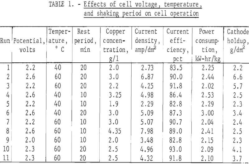
Table 1 shows the effect of the operating variables on current density In the cell. Although the period between shakings of the cathode had little effect, increasing either temperature or cell potential increased the current density substantially. It can be seen in table 1 that the tests with higher voltages also have corresponding higher copper concentrations to keep hydrogen evolution below the set level. The effect of voltage alone on current density or efficiency cannot be seen from these tests since copper concentrations were not held constant:
Note.-Operation conditions:
174 g/l NaCl
1.8 g/l HCl
2 g/l Fe++
Hydrogen detection control of Cu concentration.
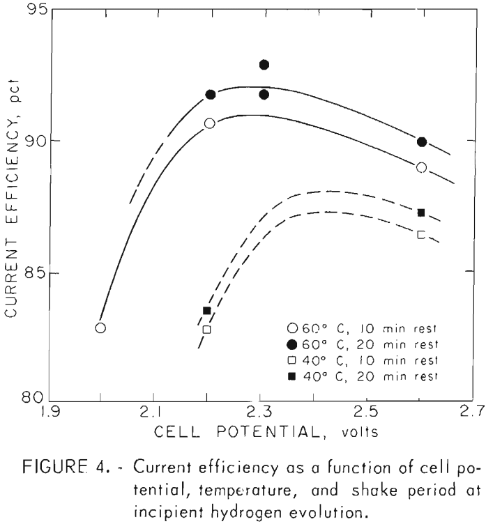
Figure 4 shows the effects of the operating variables on current efficiency. Higher temperatures increase current efficiency while the longer period between shaking the deposit from the cathode produces only a small increase in cell efficiency.
Examination of table 1 shows that cathode holdup (the amount of copper left on the cathode at the end of the run) is greater at 60° C and a 20-min rest period between shaking than at 60° C and 10 min or at 40° C for either period. This is also reflected in the behavior of the cell concentration. Tests made at 60° C and 20-min rest periods showed the greatest differences in copper concentrations when compared with 10-min rest periods, particularly at 2.6 volts. The lower concentration is due to the greater cathode area presented by the larger buildup of copper on the cathode when longer periods between shaking are used. It can be seen, however, that excessive cathode holdup would clog the cell and that conditions must be such that the product sloughs adequately from the cathode.
The first series of tests showed that higher temperatures provide better current density and also better current efficiency. Further testing as shown in table 2 was therefore done at 60° C and 20-min rest periods between shaking the powder from the cathode.
The hydrogen detection control method gives excellent current efficiency as shown in figure 4 since copper concentration is minimized in the electrolyte and yet kept high enough to minimize current losses due to hydrogen evolution. However, with this method it is impossible to test the effects of cell voltage and copper concentration independently.
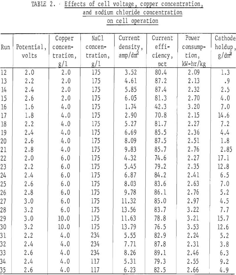
Independent control of cell concentration and voltage were easily maintained by the colorimetric control method. The results of tests run at various cupric ion concentrations, voltages, and sodium chloride concentrations are shown in table 2. Synthetic cell solutions were used in order to insure uniform compositions from one test to the next. All the solutions contained ferrous iron and HCl at 2.0 and 1.8 g/l, respectively.
Note.-Operating conditions:
1.8 g/l
HCl 2 g/l Fe++
T = 60° C
Colorimetric control of Cu concentration.
20-min rest period.
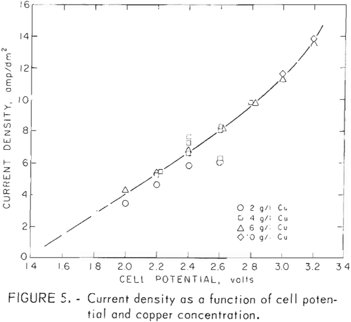
Current density and current efficiency are shown for cupric chloride electrowinning tests in table 2 and also in figures 5-6. Figure 5 shows current density to be almost linearly dependent on cell voltage and nearly independent of cupric ion concentration. Current densities are somewhat lower for the 2-g/l tests than for those at 4 and 6 g/l for cupric ion electrowinning.
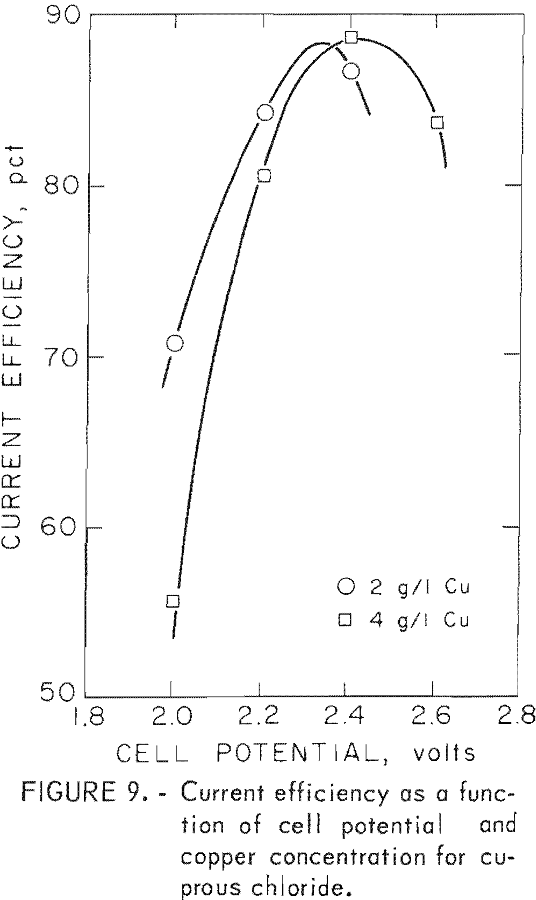
Figure 6 shows the effects of voltage and cupric ion concentration on current efficiency. It can be seen that current efficiency rises to a peak with increasing potential and then declines. Increasing copper concentration shifts the peaks toward higher voltages and also broadens them. Declining
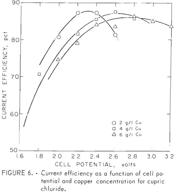
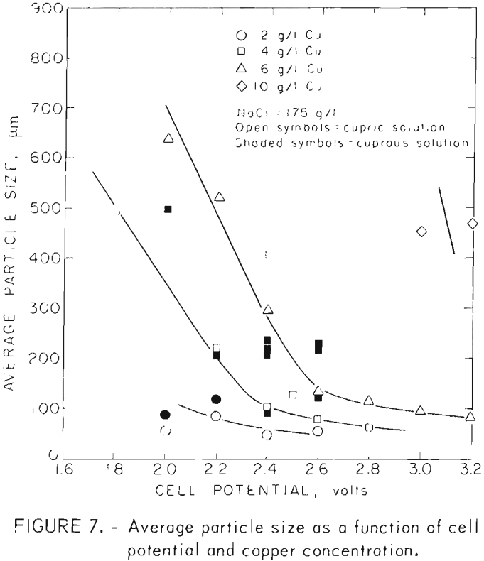
current efficiency at voltages above the peak is due to increasing hydrogen evolution, at higher voltages for a given copper concentration. A similar change in behavior is shown in figure 7. Here the particle size changes much more slowly in the higher voltage region where hydrogen evolved. Decreasing efficiencies at voltages below the peak are due to convective losses. These losses occur when the chloride system is electrolyzed and must be reduced through the use of a diaphragm in the cell.
Elemental chlorine generated at the anode is somewhat soluble in aqueous brines and must be isolated from the cathode compartment. At the cathode, partial reduction of cupric ion and/or attack of the copper product by cupric ion produces cuprous ion. When chlorine-rich anolyte and cuprous-rich catholyte are allowed to mix, they react to form cupric chloride , and the cell is partially short circuited.
The diaphragm reduces convective losses but with diminishing effectiveness as the operating rate falls at lower cell potentials.
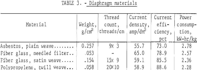
Table 3 lists the material tested for diaphragms. These range from a highly permeable asbestos cloth to a tightly woven polypropylene twill. Reduced porosities increase current efficiency but generally decrease current density.
The glass cloth that gave almost as good power consumption and current efficiency as the polypropylene cloth was used throughout the bulk of the investigation. The polypropylene showed a 25 pct weight gain during 100 hours exposure to the hot chloride solution and was therefore considered inferior to fiber glass.
Note.-Operating conditions
4 g/l Cu
174 g/l NaCl
60° C
2.4 volts
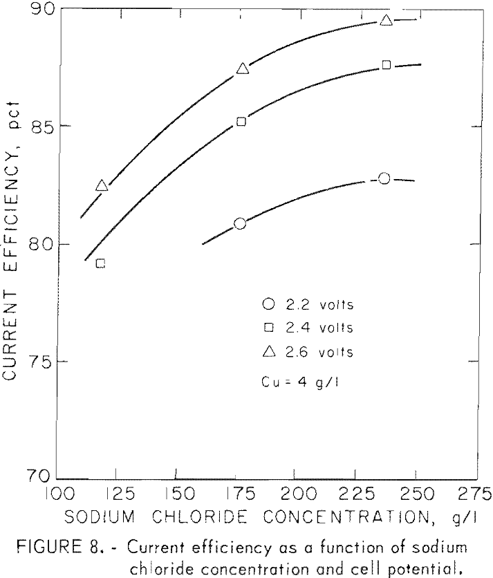
The effect of sodium chloride concentration in the brine was investigated under the more precise conditions provided by the colorimetric control method. Table 2 and figure 8 show that current efficiencies increase with sodium chloride concentration but show little improvement between brine concentrations of 175 and 234 g/l. As shown in table 2, the bulk of the tests were made with brines with 175 g/l sodium chloride.
The electrolysis of cuprous chloride solutions was also investigated. Such solutions would be generated if silver removal by cementation on copper were used or if a more economical means were found (other than electrolysis) for reducing cupric ions to the cuprous state.
The concentration control circuit could not be used with cuprous chloride solutions since they are colorless. The current monitoring control method described earlier were therefore used to maintain the desired copper concentrations in the cell.
The results of these tests are shown in table 4 and figure 9. Figure 9 shows the effect of cell voltage on current efficiency for solutions containing 2 and 4 g/l copper. As with cupric chloride electrolysis, current efficiency rises to a maximum and then declines as the cell voltage is raised beyond the point where hydrogen evolution begins. With cuprous solutions, the peaks are much sharper than with cupric solutions. They show maximum current efficiencies between 85 and 90 pct essentially the same as those obtained with cupric chloride feed solutions.
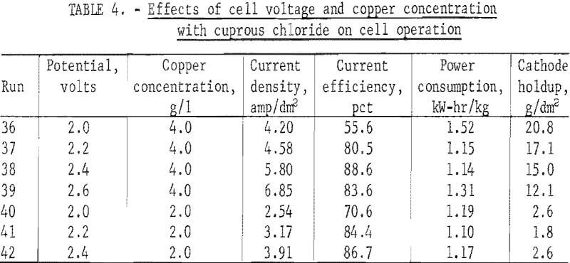
Note.-Operating conditions:
174 g/l NaCl
1.8 g/l HCl
2 g/l Fe
T = 60° C
Current monitoring control of Cu concentration
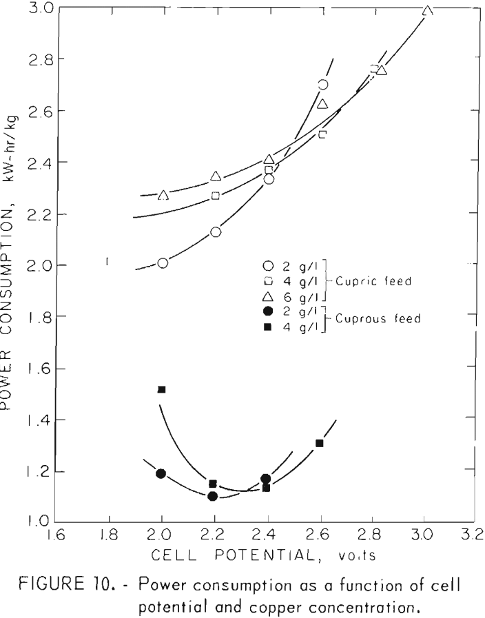
Decreasing current efficiency at lower cell voltages is partially offset by the lower power required to operate at reduced voltages. This effect can be seen in figure 10 where power consumption is shown as a function of voltage for both cuprous and cupric solutions at different concentrations. The lower power levels needed to process monovalent cuprous solutions are demonstrated here. It should be remembered, however, that advantage can be taken of these lower power requirements only if an inexpensive means is found to prereduce cupric solutions to the cuprous state. Efforts to date to produce monovalent copper through chlorination of chalcopyrite followed by oxygenation of the mixed chlorides to render the iron insoluble have been disappointing. Only 25 pct of the copper has been produced in the cuprous state even at oxidation temperatures over 900° C. At 500° C good oxidation occurs, but the copper chlorides are 100 pct in the cupric state.
Another disadvantage of cuprous chloride is its high affinity for oxygen and the subsequent formation of insoluble oxychlorides. This requires covered containers for solution storage if oxidation is to be prevented and problems caused by unreduced copper oxides in the powder product are to be avoided.
Product Characteristics
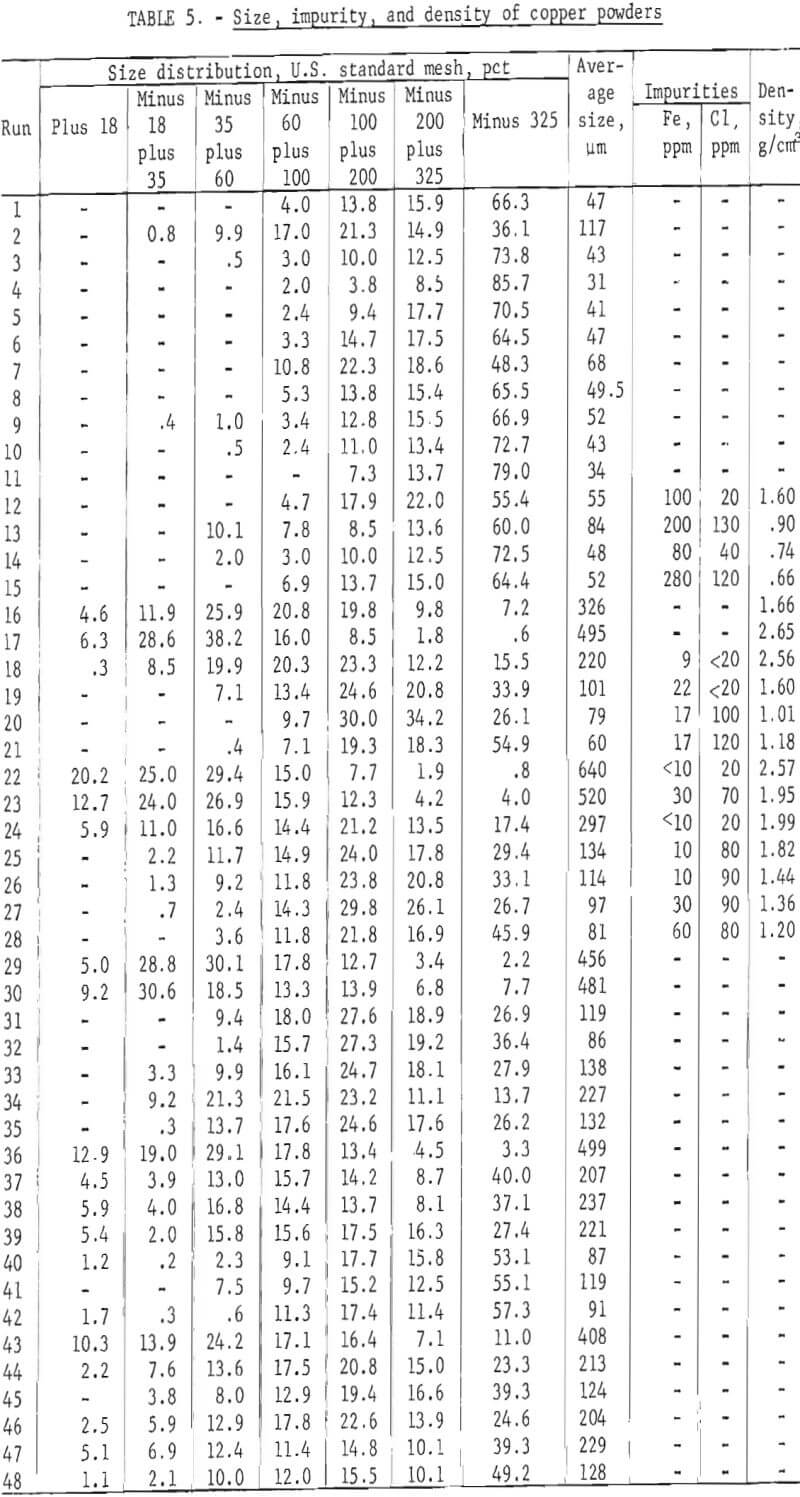
Copper powder production by electrolytic methods has been investigated. Electrowon copper from this chloride process was screened through a U.S. sieve series stack containing 18-, 35-, 60-, 100-, 200-, and 325-mesh screens on an Allen-Bradley sonic sifter. A weight average particle size was then calculated. Average powder sizes for the last fraction are shown in table 5 and also in figure 7.
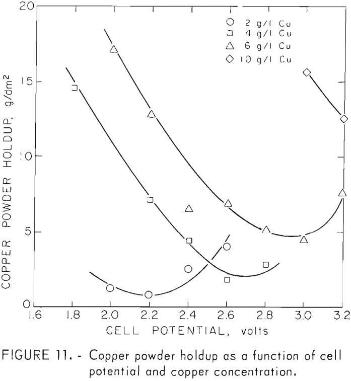
Good correlation of powder size with copper concentration and cell voltage for electrowinning of cupric chloride solutions is shown in figure 7. In the case where more concentrated solutions were processed, a definite break can be seen in the curves. In both cases , the break is in the area where hydrogen evolution begins as higher voltages are applied. Evolution of hydrogen apparently causes the particles to be loosely attached to the cathode and allows them to slough off before growing large. The effects of hydrogen evolution on ease of product removal can be seen in figure 11 where cathode holdup is shown as a function of cell voltage.
Results from table 5 (runs 1-11) also shows particle sizes for powders made using hydrogen detection as the control mechanism. It can be seen that the hydrogen-controlled tests produced particle sizes and cathode holdup values near the minima attained with cupric solutions using colorimetric control. Higher cathode holdup when higher voltages are used with hydrogen detection control is due to flotation of the spongelike copper product with hydrogen bubbles. Flotation is less of a problem when closer concentration control is maintained with the colorimetric control circuit and intermittent surges of H2 evolution do not occur as they do with a H2 detection control system.
The darkened points on figure 7 represent tests made with cuprous solutions and also solutions made by leaching and product of chlorinated and then oxidized chalcopyrite. These products were larger and their sizes correlate poorly in comparison with those made from cupric chloride solutions. This is believed to be due more to the control method than to the oxidation state of the copper ions. With the current control method used with cuprous solutions, much wider concentration changes occurred before off-on action was triggered. This allowed periods of higher concentration and promoted the initiation of more adherent, larger growing particles. In contrast, the colorimetric method used to control the cupric chloride electrolysis provided much closer concentration control. In these tests, hydrogen was either not generated or was evolved continuously at the higher voltages.
The smaller powders were needlelike while the larger sizes became dendritic. None would flow freely and were of very low density as shown in table 5. Hydogen sintering at 750° C and hammer milling made the powders flowable through a Hall flowmeter and increased their densities. Although this procedure was not pursued quantitatively, it was found that flowable powders could be made from the electrowon copper. These powders would be suitable for powder metallurgical operations with appropriate sintering, milling, and screening to produce the desired flowability and size distribution.
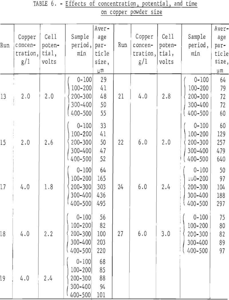
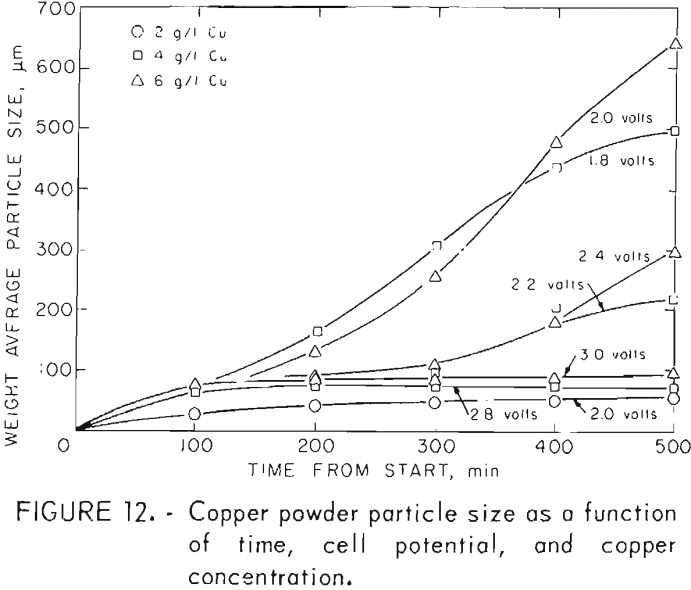
The aforementioned size analyses are based on the assumption that the powder product had attained a steady-state size distribution after 400 min operating time. Several tests representing the range of concentrations and applied voltages were analyzed as to weight average size as a function of time from the start of the test. The results are shown in table 6 and figure 12. It can be seen that at higher voltages and lower copper concentrations the products come quickly to an equilibrium size. At lower voltages and higher copper concentrations, the weight average size levels off but is still increasing in some cases after 500 min. This indicates that the steeper parts of the curves in figure 7 should be even steeper than shown. A production facility would, however, operate under the higher voltage conditions where the curves are flat after 200 min. These smaller sizes are therefore representative of steady-state conditions.
Only limited work was done with solutions prepared from chalcopyrite. These were made by chorination of the mineral concentrate followed by oxygenation to make the iron insoluble. Leaching of the soluble copper chlorides with brine provided the electrolyte.
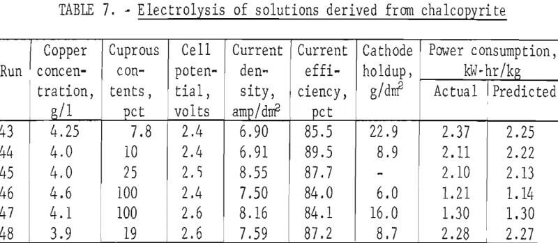
Results of these tests can be seen in table 7 and can be compared with those derived with synthetic solutions. An attempt was made to operate near optimum conditions, and table 7 shows current efficiencies near the peaks shown in figures 6 and 9 for solutions containing 4 g/l copper. The current efficiencies shown in table 7 are near or above the maxima of 87 and 88 pct obtained for cupric and cuprous ion electrolysis, respectively.
Note.-Operating conditions:
T = 60° C
Current monitoring control of Cu concentration.
Cathode holdup and particle sizes can also be compared and found to be similar for synthetic solutions and those derived from processed chalcopyrite. Residual copper powder on the cathode was generally between that found for synthetic cupric and cuprous solutions when processed chalcopyrite solutions were used. Similarly, table 5 shows average particle sizes for tests with processed chalcopyrite solutions (runs 43-48) that are of the same magnitude as those made with synthetic solutions at similar operating conditions.
Of the various operating parameters, power consumption shows the greatest variation between operations using cuprous and cupric salts. The predicted power consumptions shown in table 7 were calculated by determining the power required for both cupric and cuprous electrolysis from figure 10 at the operating conditions used. The resulting power levels were then multiplied by the cupric and cuprous fractions in the feed solution and the products added. Table 7 shows good agreement, within 6 pct, between actual and predicted power consumptions. One can, therefore, predict power requirements for a given set of operating conditions by taking the sum of the requirements for the cupric and cuprous fractions in the process solution.
Analyses obtained on solutions and products are shown in table 8 along with specifications for casting grade copper. It can be seen that iron and lead levels are below the specifications while the low levels for bismuth are not met in the two metal samples analyzed.
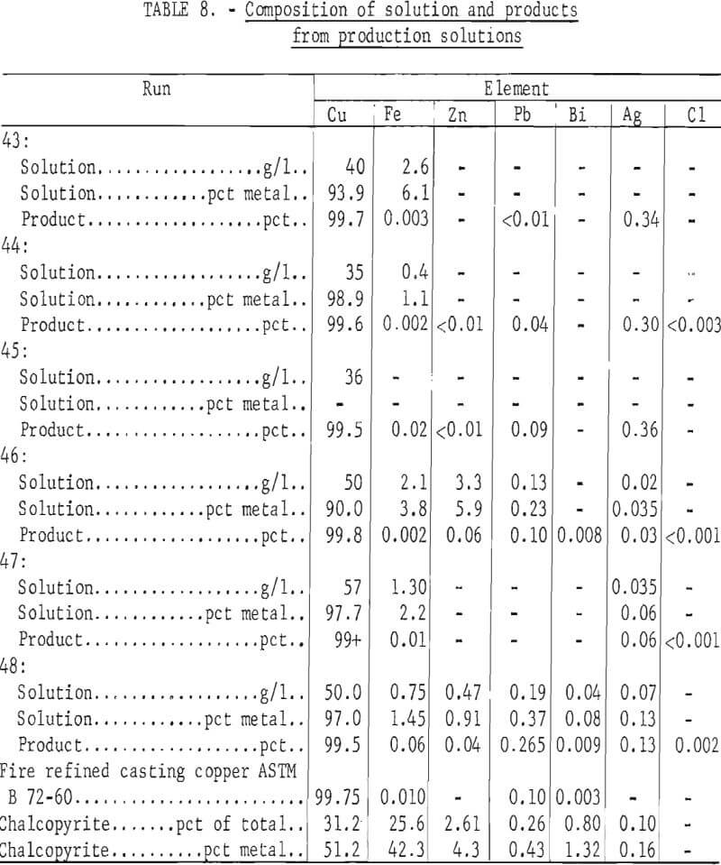
The low silver content in the feed solution and products for runs 46 and 47 in table 8 are due to cementation of the silver on elemental copper. This can also be seen in table 6 where the copper is shown to be completely in the cuprous state. Around 90 pct of the silver was extracted in both cases, but cuprous solutions must then be dealt with. Electrorefining would provide better silver recovery and might be preferable to silver cementation on copper.
Conclusions
Copper can be efficiently electrowon from chloride solutions in a diaphragm cell. Partition is required to confine the chlorine product to the anode compartment and to prevent interaction between the chlorinated anolyte and the partially reduced catholyte.
Electrowinning operations can treat either cuprous or cupric chloride solutions. Cuprous chloride has a high affinity for oxygen and must be protected from the atmosphere to prevent the formation of insoluble oxygen compounds. Power consumptions of 2.1 and 1.1 kW-hr/kg were obtained for cupric and cuprous chloride solutions, respectively.
Electrowinning copper from chloride solutions favors the production of powders rather than plates. Blends containing more than 50 pct minus 325 mesh can be produced. High current densities and low copper concentrations favor the formation of fine particles. Direct production of a premium powder product is a distinct advantage of electrowinning from chloride solutions.
