Table of Contents
The gradual depletion of high-grade mineral deposits and the necessity for development of lower-grade deposits, together with the increased demand for nonmetallic minerals, has increased the importance of the ore-dressing field during recent years. There is strong need for development of new ore-concentration methods and machines to keep pace with the constant changing of marketing specifications and requirements resulting owing to the many-new uses made of mineral products by the metallurgical industry.
Many ores are not readily amenable to concentration by gravity, flotation, or other conventional methods. For example, the dry separation of minerals having a small specific gravity difference is an extremely difficult problem. Therefore, the Bureau of Mines has conducted research to develop new treatment procedures and to develop new types of ore-dressing equipment. As a part of this program, studies were made and equipment was developed to separate minerals according to physical characteristics ‘other than specific gravity.
This paper describes three dry-ore concentrators developed to separate minerals of different shape, magnetic susceptibility, or electrostatic conductivity, named:
A. Vibrating -deck mineral shape separator.’
B. Electrostatic -mineral shape separator.
C. Progressing field magnetic separator.
Each of the separators has a high-frequency vibrating deck that can beneficiate comminuted ore to make a split of the ore minerals on a basis of their shape or size rather than difference in specific gravity. In addition to a vibrating deck separator B includes several electrodes, both grounded and high-voltage, which add electrostatic forces for further mineral beneficiation. Separator C combine’s an electromagnetic armature with a vibrating deck in order to separate magnetic from nonmagnetic ore particles.
Vibrating-Deck Mineral Shape Separator
Description
This separator is designed to separate minerals with characteristic differences in shape it is particularly adapted to the separation of tabular particles from rounded particles.
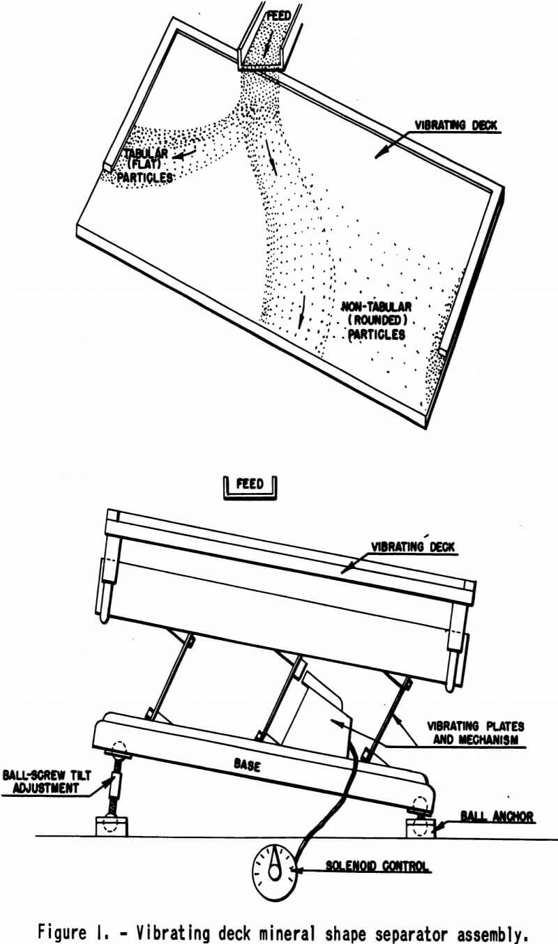
The machine (figs. 1 and 2) consists of a base and a vibrating deck motivated by a solenoid-type vibrator which is controlled by a variable transformer. The deck may have a flat or curved longitudinal section and can be constructed of a variety of materials; fir plywood was found to be suitable for the laboratory model. The deck and base are connected by three equal-length flat springs set in parallel planes. The base is supported on ball and socket joints, so that the separator may be adjusted to any desired angle as governed by the nature of the material being treated. The vibrator mechanism is mounted on the base between two of the springs.


The laboratory model of the separator is designed and balanced to vibrate at a natural frequency of 66 cycles (120 impulses per second), the frequency of the electromagnetic system. For its construction to operate at any other frequency it would be necessary to change the design of deck load or spring dimensions.
The forces controlling the separation of minerals on the deck are variable and are balanced by adjustment of deck slope and the amplitude and intensity of the deck vibration. Once adjusted for. a particular size and type of feed, the machine requires little attention.
A vibrating feeder is used to discharge the ore to the deck. Each mineral particle. moves across the sloping deck in the direction of the resultant of the forces acting upon it. The spring throw of the tilted deck causes a differential movement that conveys the tabular mineral grains up the deck slope and, in addition, retards the downward movement of the rounded grains. Friction between the deck and the tabular particles must be sufficient to prevent downward slipping between impulses.
The shape separator products are collected from three sides of the deck. The flake travels to the top end, the thick tabular grains to the side, and the round particles roll to the bottom or lower end.
Grading according to shape is positive. Very little sweeping of flake occurs from the downward movement of the rounded grains. Therefore, a particle repassed over the deck will return to its respective bin. In general, best results are obtained when dry, closely sieve-sized ore is fed to the separator. The ore should be crushed in such a manner as to produce a low percentage of fines and to cause as little damage as possible to the shape characteristics of the liberated grains. Products that contain locked middling particles can be reground and retreated with finer fractions of the ore.
Illustrative Tests
Two tests have been included to illustrate the effectiveness of the vibrating deck shape separator.
Separation of Vermiculite from Gangue
Vermiculite ore from Montana, which contained, in order of their abundance, vermiculite, pyroxene, hornblende, nepheline, and chlorite, was treated on the shape separator. A sample of ore was crushed to minus 10-mesh and closely screen-sized. Each fraction was treated separately to make a concentrate, middling, and tailing. The middlings were dry-ground, sized, and added to the respective finer sizes prior to shape-separation, treatment. The final middling was rejected with the tailing. The minus 100-mesh material was not treated. Microscopic grain counts were used in reporting the percentage of vermiculite in each product as chemical assays were not indicative of the mineral composition of the test products. Data are shown in table 1.

By shape separation 83.5 percent of the vermiculite in the ore was recovered at 95.7 percent vermiculite grade. The bulk of the gangue in the concentrate was chlorite.
Cleaning of Graphite Flotation Concentrate
A flotation concentrate, made from a Montana graphite ore, was treated on the vibrating-deck shape separator in an effort to increase the grade of the product, maintain maximum flake size, and to produce a uniform thin-flake concentrate. The graphite in the ore occurs as books of graphite flakes with siliceous gangue included between the plates. Repeated grinding and cleaning by flotation produced high-grade concentrates, but the flake size was extremely small.
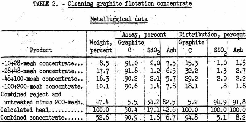
A sample of rougher flotation concentrate was screen-sized, and each fraction was treated separately on the shape separator. The tailing and middling products from each fraction were dry-ground in a pebble mill to separate the flakes from the thick tabular books with a minimum of flake breakage. The reground product was sized and added to the respective finer sizes before treatment. Results are shown in table 2.
By shape tabling, the grade of the graphite concentrate was increased from 50.4 to 90.9 percent C with a recovery of 94.8 percent of the graphitic carbon in the flotation concentrate. Over 91 percent of the ash and nearly 95 percent of the silica were rejected. Over half of the recovered graphite was plus 60-mesh, and the flakes were uniformly thin.

Summary
The vibrating-deck shape separator has been successfully employed in the laboratory for numerous separations of flat particles from rounded or angular material. From sized fractions of feed, muscovite mica has been separated from feldspar and quartz; flake graphite from quartz, feldspar, and ether gangue minerals; slate from coal; molybdenite from pyrite and chalcopyrite; vermiculite from; pyroxene, hornblende, and other gangue-minerals; and wood chips, grass. roots, and other carbonaceous matter from foundry sand.
In addition, a product containing free mineral grains of uniform shape can be sized by the separator with the elimination of two difficulties of sieve-sizing blinding of sieve-openings and mesh wear. Feldspar sand products and clay samples have been sized by this method.
Electrostatic Mineral Shape Separator
Description
The electrostatic mineral shape separator is a machine on which the liberated minerals of a comminuted ore are beneficiated by the surface action of a high frequency vibrating deck and by an electrostatic field maintained at the deck edges. It is designed to segregate those mineral particles that differ from others by shape, size, and electrical conductivity. Whenever there is little shape difference between the liberated mineral particles of an ore, the deck mainly sizes the sample as it progresses toward the electrostatic field.
The separator consists of a deck, base, and vibrator system similar to those of the vibrating deck-shape separator. Three edges of the deck are covered with grounded copper sheeting. High-voltage needle-type electrodes are placed opposite and several inches from the deck edges. In the laboratory model of the separator, the needle electrodes are charged with 60- cycle, pulsating, direct current obtained from a transformer and electronic tube rectifier set; the voltage employed is usually 50,000 volts.
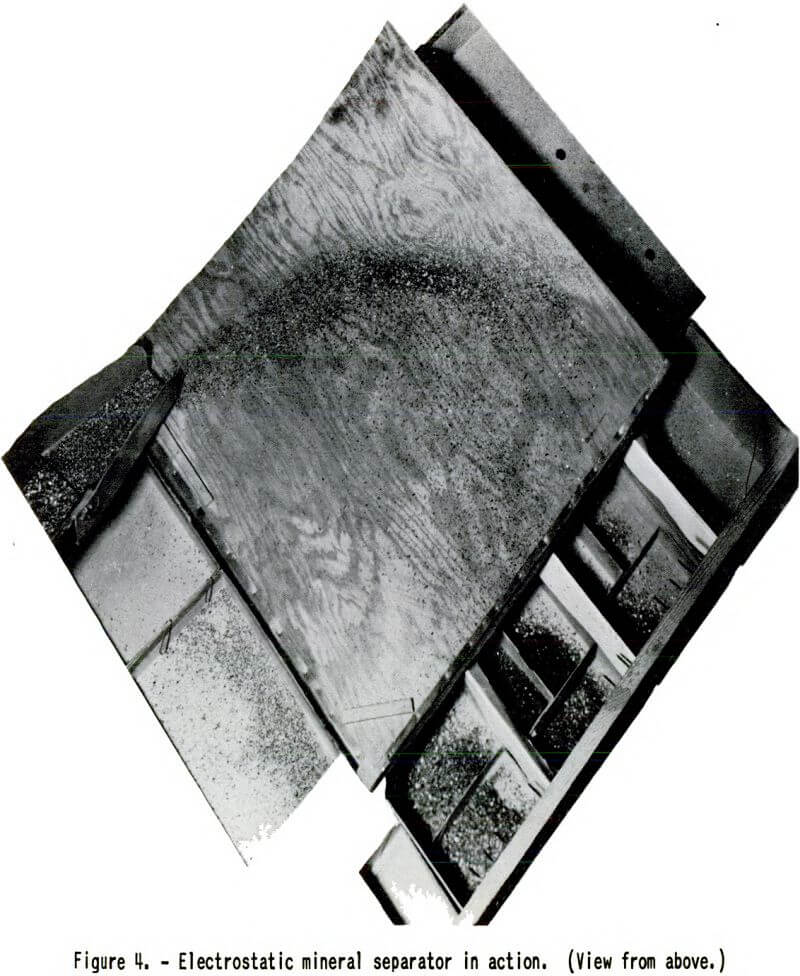
Ore particles, fed to the deck by a vibrating feeder, are separated by size and shape and, as they leave the deck, momentarily contact one of the grounded copper electrodes. Some of the particles are charged with polarity opposite that on the high-voltage needle electrodes and consequently are attracted across the intervening space to the needles, where they discharge on contact and fall to the concentrate bins directly below. Any particles that retain a charge like that of the needle electrodes are repelled under the deck edge to other bins. The remaining particles, which are not effected by the electrostatic field, are caught in bins directly below the deck edges. As the distribution of particles by shape or size is closely controlled by the vibrating deck, the electrostatic products are high in grade.
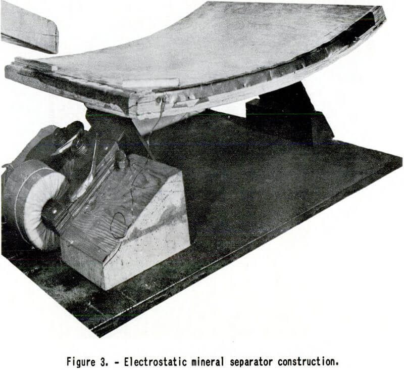
Figure 3 shows the construction of the deck, and figure 4 shows one sot of high-voltage needle electrodes in place. Other sots of needle electrodes may be placed opposite the top and bottom edges of the deck when they arc needed to complete an ore separation.
Illustrative Tests
Data have been included to compare the results of vermiculite concentration by the electrostatic mineral shape separator and by air classification.
Beneficiation of Vermiculite
A minus 16-mesh tailing product from a commercial vermiculite mill was treated to recover a plus 35-mesh high-grade vermiculite concentrate. One sample was screened on 35-mesh, and the oversize was treated on the laboratory electrostatic mineral shape separator. One pass over the machine produced a finished concentrate, a middling, and a finished tailing. The middling was retreated once to give a small amount of additional concentrate and tailing and to reduce the bulk of middling. A second sample was treated in a laboratory elutriator-type air classifier. In both tests, microscopic grain counts were used to determine the percentage of vermiculite present in the various products. Data are summarized in table 3.
By treatment on the electrostatic mineral shape separator 80.5 percent of the vermiculite in the feed was recovered at 95 percent vermiculite grade. Air separation treatment of the same product recovered 67.7 percent of the vermiculite at slightly lower grade; also, more closely sized fractions of. the ore were required to give concentrates of comparable grade.


Summary
Many ores have been found to be amenable to beneficiation by treatment on the electrostatic mineral shape separator. Some of the separations successfully made in the laboratory are listed below:

The chief advantage of the separator over conventional electrostatic separators is that it, in itself, gives a preferential sizing of material prior to and during electrostatic separation, thus precluding close screen- sizing of feed when high grade concentrates are a requisite.
Progressing Field Magnetic Separator
Description
This is a dry magnetic ore separator on which liberated minerals of a pulverized ore are concentrated by a high-frequency vibrating deck and by a progressing magnetic field. It is designed to separate particles according to their magnetic susceptibility, size, and shape.
The machine has two principal parts – the high-frequency vibrating deck, which controls the mechanical movement of the ore, and the direct-current magnetic rotating armature that develops the progressing field for ore separations.
As shown in figure 5 (a longitudinal section of the separator), the deck is a rigid construction of a series of flat surfaces arranged one above the others, each slightly narrower than the one below. The deck is made of non- magnetic and preferably nonconducting materials, as eddy current interference is high if electrical conductors are used. Fir plywood or pressed- wood sheets were found satisfactory for construction of the laboratory model.
On the laboratory machine, the deck is mounted to a heavy wooden base by means of two parallel sheet-steel springs. The lower end of the springs are anchored solidly to a heavy block, which in turn is bolted to the base. The deck is fastened to the springs with hinges having machine-fitted joints. Deck vibration is caused by the vibrator composed of an electromagnet and plunger fastened solidly to the base and the top end of the roar spring, respectively. The vibrator operates on a half-wave rectified current at 60 cycles per second.
The armature is made of a four-pole Armco iron core, four coils, two roller bearings, two slip-ring contacts, and a pulley drive. The coils contain approximately 550 turns of No. 16-gage, single, cotton-covered, enameled magnet wire held on the core with No. 11-gage nonmagnetic chromel wire. They are connected in series and have a total of 15.8 ohms resistance on a 110-volt, direct-current circuit. The armature has alternating north and south poles, so that when it is rotated a progressing magnetic field is created.
Unsized ore is fed to the top plane of the deck with a vibrating feeder. The mineral grains are all moved by the differential movement of the deck in the direction of the spring throw. The magnetic particles are affected by the armature rotating immediately below the deck. Clockwise rotation of the armature causes counterclockwise rotation of the magnetic ore grains and moves them in the direction opposite that of the deck vibration.
Separation is controlled by the tilt of the deck, the rotation speed of the armature, and the intensity of vibration of the deck. These factors are regulated to maintain sufficient friction between ore particles and the deck to move the grains in the proper direction and to break up chaining and clamping of highly magnetic particles reducing the entrainment of gangue and forming a fluid bed of easily separated ore grains.


Figure 6 is a photograph taken during beneficiation of a finely crushed, unsized magnetite ore. The ore layer on the deck of the separator is so dispersed by the progressing magnetic field and vibrating deck that the magnetite concentrate produced entrains very little gangue.
Figure 7 shows the clumping and chaining of magnetite in a stationery magnetic field. For this photograph the current was left on in the rotor coils but was switched off all the other separator controls.
Illustrative Tests
Data are included to show the treatment of identical samples of fine magnetite ore on the progressing field magnetic separator and on a magnetic separator of conventional type.
Concentration of Magnetite Ore
Samples of magnetite ore were ground in a ball mill to minus 100-mesh, deslimed by decantation, and dried. One sample of sand was passed once over the progressing field magnetic separator; a second sample was given like treatment on a disk- type, high -intensity, dry magnetic separator. In both tests the slime fraction was rejected. The slime contained 15.9 percent of the original weight of the ore at a grade of 21.7 percent Fe and represented a loss of 7.9 percent of the total iron. Comparative data are shown in table 4.

As is shown in table 4, the progressing field magnetic separator made a cleaner concentrate than the disk-type separator with about the same recovery. In addition, the progressing field machine treated the material at the rate of 160 pounds per hour, as compared with 36 pounds per hour for the disk- type separator.
Summary
The progressing field magnetic separator has been found successful in the laboratory for the separation of magnetic from nonmagnetic particles in unsized ore. The capacity is fairly large, end, when properly controlled, the concentrates are virtually free of entrained gangue.
It is particularly effective in the finer size ranges (minus 48-mesh) and has been used to make concentrates of magnetite, magnetite-ilmenite, and sponge iron.
General Summary
Three new dry-mineral concentrating machines have been developed at the Intermountain Experiment Station and tested in the laboratory. They were found to be satisfactory for specific types of mineral separation.
The vibrating-deck mineral-shape- separator is designed to separate flat or tabular particles from rounded or angular material. Flake material such as graphite, molybdenite, and mica has been separated successfully from quartz, feldspar, or other gangue materials.
The electrostatic shape separator combines sizing, shape separation, and separation according to difference in electrical conductivity of particles. The chief advantage of this machine over conventional-type electrostatic separators is that it sizes the material prior to separation and produces high-grade concentrates without screen sizing the feed.
The progressing field magnetic separator has been used successfully to separate magnetic from nonmagnetic particles in unsized ore. It is especially effective in the range of finer sizes and the capacity is large in comparison to standard laboratory magnetic separators.
