The problem of tramp iron removal from moving ore belts is a long standing one. When heavy ore streams are carried on a belt, magnetic pulleys and strong surface magnets fail to remove tramp buried in the ore stream. Tramp iron buried in the ore stream cannot be pulled from the bed by surface magnets and is carried past the magnetic pulley by the falling ore stream.
Several types of tramp detectors have been developed. It would serve no practical purpose here to review exhaustively the literature on the subject. Methods of tramp detection used are: (1) The magnetic method, wherein the small current generated by the magnetized tramp passing a coil is used. (2) The unbalanced oscillator method wherein the tank circuit of a stable radio- or audio-frequency oscillator is unbalanced causing a change of frequency or a change in plate current due to changes in eddy currents, hysteresis, or dielectric because of the presence of tramp. (3) The bridge methods wherein the impedance of one leg of an alternating current inductive bridge is changed due to the presence of conducting tramp.
At the Caselton, Nevada, plant of the Combined Metals Reduction Co., sulphide ores are treated; therefore, it was necessary that a tramp detector operating on only the magnetic properties of the tramp iron be used.
Tramp iron detectors of this type operate on the principle that if a piece of tramp iron moves near a coil in a high intensity, steady magnetic field, the presence of the moving tramp iron causes the magnetic flux lines through the coil to change. This induces a small current in the coil. In series with the coil is generally placed a relay sensitive to currents of 1 to 3 microamp. When the tramp iron passes near the coil the flux linkages change, causing this very sensitive relay to actuate. Since the contacts of such a relay are very small it must actuate a second relay capable of breaking a larger current which in turn actuates another relay and finally the power circuit on the belt, thus stopping the belt.

Certain of the steels, particularly the high manganese steels, do not exhibit very strong magnetic properties.
New Detector: First of all the many relays were eliminated; there is only one heavy duty relay in the apparatus that is capable of making or breaking 5 amp at 440 v.
Since the belt moves slowly, the current generated by the detector coil is essentially a direct current. It is difficult to construct a simple direct current amplifier that is stable over long periods of time.
Between the tramp detector coil and amplifier is placed a “Brown converter,” which is a special vibrating reed, single-pole doublethrow switch developed by the Brown Instrument Division of the Minneapolis-Honeywell Regulator Co. for use on their “Electronick” recorders and controllers. This device will produce an absolutely square wave 60 cycle current from a direct current source.
In the installation at the Caselton plant the detector coil is 4 in. long and 40 in. wide and is placed under the belt and very close to it. It has 1000 turns of No. 20 wire and is completely shielded with a copper Faraday shield to prevent electrostatic pick up.
The magnets supplying the steady magnetic field are located above the belt. These are electromagnets


and are supplied with direct current from a motor-generator set.
Through adjustment of the sensitivity control the apparatus is made sufficiently sensitive to detect iron and steel objects the size of rock bits while it does not in general detect small nails. It has been found that a 20 d nail in the bottom of the ore pile, nearest the coil, will sometimes actuate the howler and marker. It depends somewhat on the orientation of the nail relative to the coil. If it is perpendicular to the coil windings it will usually cause an actuation. When the nail is perpendicular to the winds, the most number of turns of the coil are affected by the change in magnetic field.
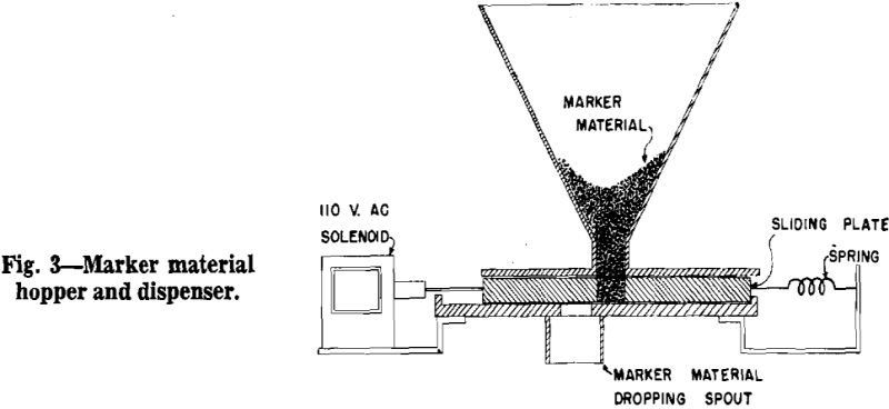
When the actuation is complete the spring pulls the plate into position to register with the hole in the bottom of the hopper again. Bumper blocks prevent excessive travel of the sliding plate and the sharp jar at the end of the travel prevents sticking. The solenoid used has a 32 ounce pull and a travel of about 1% in. This arrangement operates excellently when popped perlite is used for the marker material but it is not known if it would operate without sticking if another material were used.

