The final casting of refined copper has been restricted for generations by the following sequence of operations: Filling the reverberatory furnace, melting, skimming, blowing or flapping, and poling. The hoped-for 24 hr cycle, producing 300 tons or more, has been taken up largely with the necessary but time-consuming tasks of cleaning the bath, sulphur elimination, and in turn removal of excess oxygen to produce tough-pitch copper. Incidental to comparatively slow melting under combustion gases, copper oxides react with the furnace lining, and the slag so-formed must be completely recycled.

The three-phase arc furnace has eliminated some of the cycle stages, and telescoped the remainder into a continuous operation. Electrical energy, supplied to graphite electrodes enclosed in high grade refractories, rapidly melts copper cathodes and sustains a stream of metal, containing approximately 0.01 pct oxygen, without contamination from fuel.
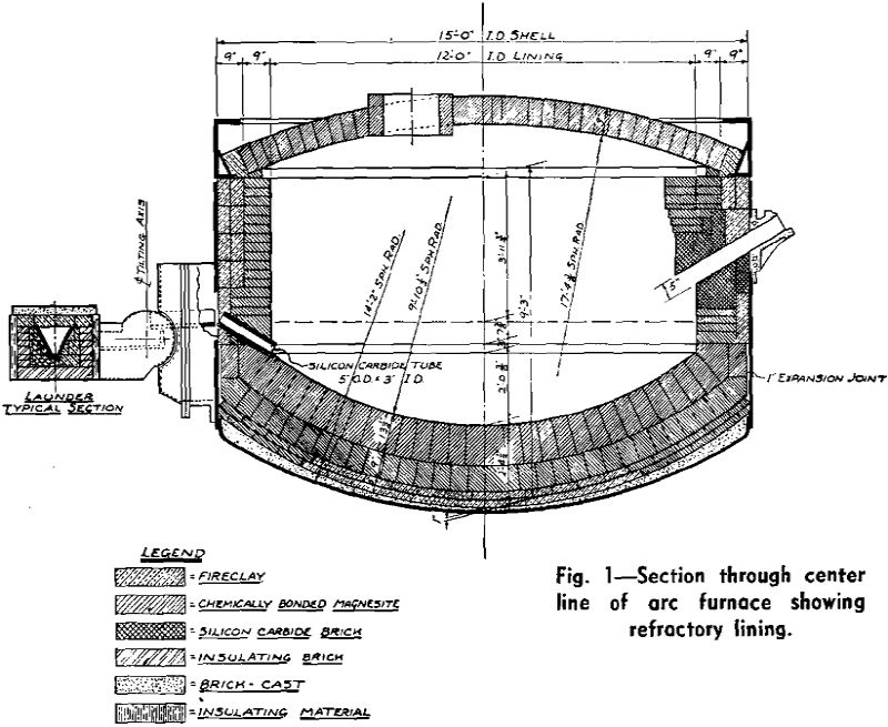
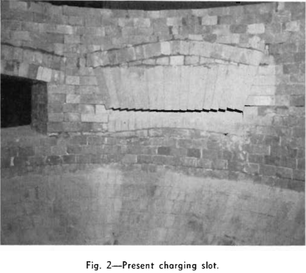
The charging slot, 3 ft 8 in. x 5 in., lies on the north center line, the tap hole on the south, and the 30×30 in. skim door 45° to the west of the slot.
Dry chrome-magnesite cement was brushed over each course after laying, and a 1-in. expansion space between the brick and the shell was filled with the same mixture. The total bottom thickness, excluding the castable material, was 5 in. of clay plus 22½ in. of chemically-bonded magnesite.
Tap Hole: A 5-in. OD and 3-in. ID silicon-carbide tube constitutes the tap hole and is set tangential to the upper course of the furnace bottom. Molten metal fills the tube when the furnace is level and filled to capacity.
Side Walls: The lining, against the shell, consists of a 9×4½x3 in. soldier course of fireclay, using straights and No. 1 arches to turn the circles. A second soldier course of 9×4½x2½-in. fireclay was laid in a somewhat similar fashion.
Roof: A single course of fire-clay skewbacks of special shape encircle the water-cooled ring. The remainder of the roof embodies standard sprung-arch construction, using bonded 9-in. magnesite of 3 and 2½-in. arches, straights, and wedges with special shapes as required to turn the circles, and with cardboard expansion joints between every fifth brick. The three electrode openings and a vent are turned respectively with 13½x4½x2½ in. and 9x 4½x2½ in. magnesite arches.
Launder: A 30-ft steel-framed launder, a cross-section of which appears on Fig. 1, connects the arc furnace with a low frequency induction furnace. Three 9×4½x2½-in. silica insulating brick line the bottom with a course along each side, laid flat, leaving 2-in. side spaces which are both filled with loose silica insulation. Suitable fireclay shapes support the central silicon-carbide V channel, formed with one 1½-in. split laid flat and two 9-in. splits at a 60° angle, giving a roughly equilateral channel 9 in. deep x 10 in. wide at the top. Joints are filled with silicon-carbide cement. Courses of clay brick, two of 12x12x2 in. and one of 12x6x3 in. cover the channel.

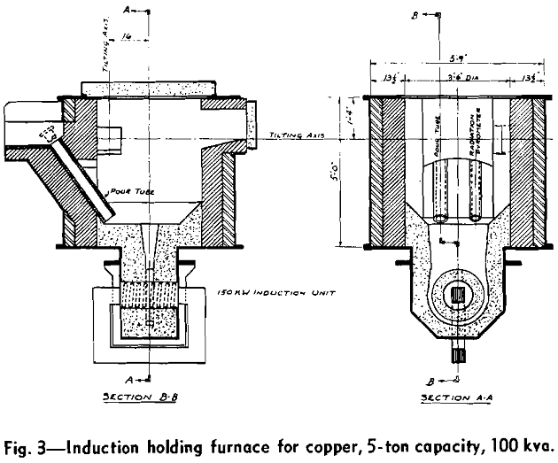
Induction Furnace: This holds about 5 tons, appears in outline on Fig. 3, and serves merely as a reservoir between the arc and the casting ladles. Power control will be described under electrical equipment. Metal enters the unit from the launder through a 6 in. OD x 4 in. ID silicon-carbide tube inserted through one furnace trunnion. The furnace pours into casting ladles through a similar tube set at an angle to allow complete drainage without going beyond 90° from the vertical.
Charging Machine: Cathodes, to be charged to the arc furnace, are piled 20 high on pallets and travel by gravity on rollers to a shear, where the loops are removed. The cathode is then pushed into the charging machine magazine, which constitutes a novel feature of the installation.
Electrical Equipment: The local electric utility company supplies power over a three-phase 60- cycle, 13.8 kv overhead line supported on wooden poles and pin insulators. The line terminates 100 ft from the furnace substation, where it changes to a three-conductor leaded cable laid underground in fiber ducts.
The transformers stand directly above their respective oil circuit breakers and are wired with single conductor, varnished-cambric, flameproof cable through fiber ducts enclosed in steel. The floor is constructed to form a liquid-tight basin to take care of a possible transformer tank failure.
The arc furnace transformer is in line with the vertical center line of the furnace and at sufficient height to minimize the heavy rigid secondary copper buswork and to provide clearance and free movement for the flexible cable loops between the bus and the electrode mast arms. The bare copper cables, connecting the bus and mast arms, consist of twenty 1,500,000 circular mil and twelve 1,750,000 circular mil cables per phase.
The low voltage, free-standing, metal-clad switch gear and controller for the induction furnace unit stands adjacent to the casting platform. This houses the main air circuit breaker, tapped autotransformer, power-factor correction capacitators, manual pre-setting tap switches, and magnetic solenoid tap changing contactor. Indicating power-factor and kilowatt meters, furnace molten metal electronic temperature recorder and controller, and furnace inductor core sleeve electronic temperature recorders are set flush on front of the switch gear cubicle.
The silicon-carbide sill still presents a problem as this material quickly oxidizes. There is apparently a reaction between the oxides of copper and the carbide, as boiling can be seen around the lower edge of the sill. A periclase brick sill will be tried at the next repair, but the furnace has operated successfully for months with little or no sill brick.
Quality Control of Metal: Delivery of good quality cathodes leaves control of arc furnace metal dependent on the three elements: Oxygen, sulphur, and iron. This resembles reverberatory practice, but manipulation differs. The three elements are dealt with in order.

Crystalline material within the loop has proved most difficult to eliminate. While the shears cut off the loop and upper 10 pct of the cathode, experience has shown that sulphates, if not removed from the loops in the dip tanks, slowly dissolve and run back over the body of the sheets while still wet.
Slag: Slag formation varies directly with accidental or deliberate additions to the bath. Because of the very refractory character of the furnace lining, the skimmings should not be termed slag, as they consist of semifused crusts impregnated with copper shot and oxides. The analysis of the September skims was: Cu, 21.71 pct; Fe2O3, 2.86; Al2O3, 3.89; SiO2, 20.00; CaO, 4.68; MgO, 33.28; and Cr2O3, 8.90. Ignoring the copper, the remainder corresponds to an accidental mixture of roof and wall brick plus a minor amount of magnesite cement.
The arc furnace is rated at 20 tons per hr. This rate has not been reached yet over an extended period; the best daily tonnages have been approximately 15 tons per hr, but over shorter periods the rated capacity has been approached.
