The essential elements of thickener basin construction consist of:
- Laboratory testing and selection of soil materials for thickener bottom and determination of required thickness of treated blanket.
- Rough grading of site to bottom slopes of thickener basin. If imported soil materials are to be used, establish rough grade at bottom slopes minus 150 to 450 mm to allow for placement of imported materials.
- Excavation for thickener access tunnel and center pier foundation or caisson foundation.
- Form and place concrete for tunnel and pier foundation.
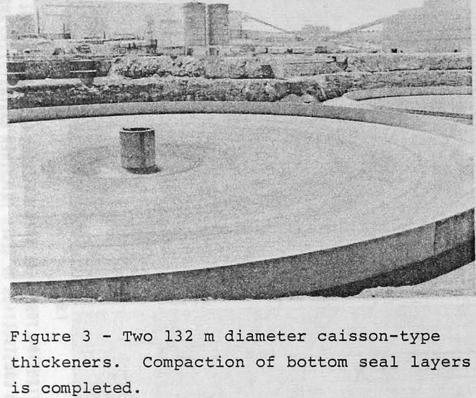
- Backfill over tunnel and compact to specified density.
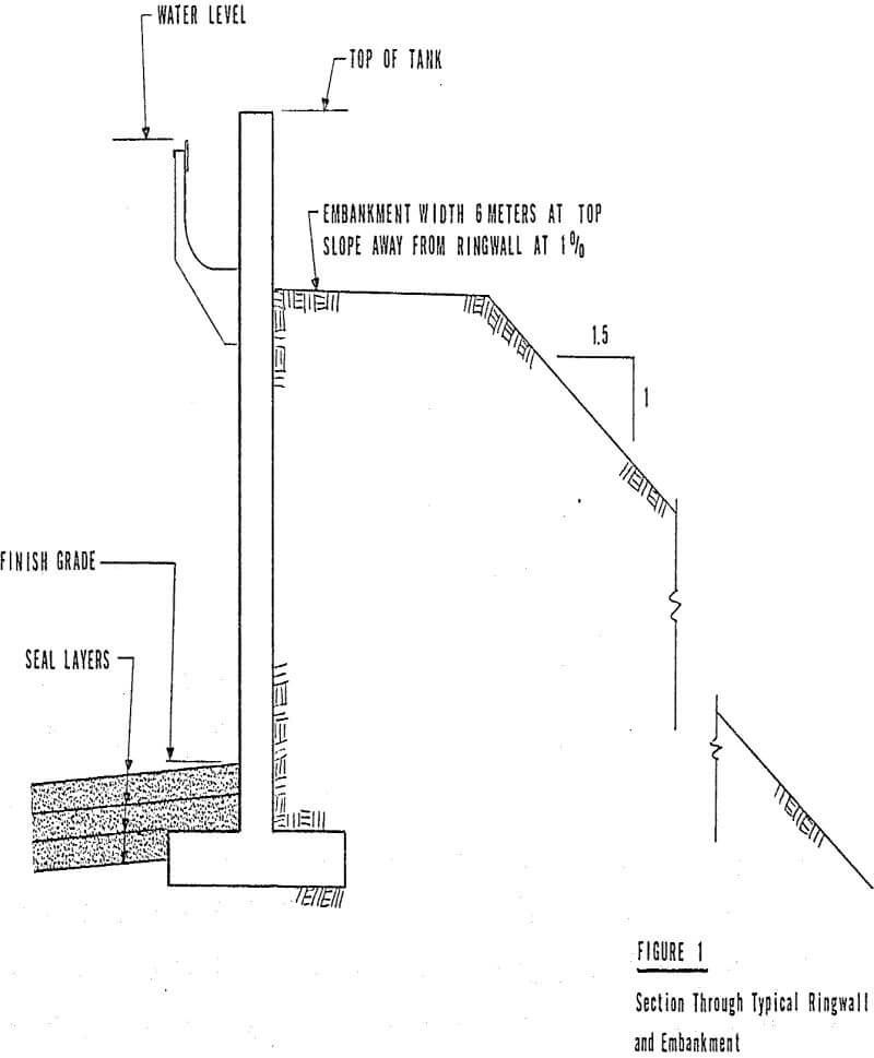
The perimeter wall (or ringwall) is designed as a simple retaining wall to withstand hydraulic pressure exerted by the slurry and to retain the earth embankment. Wall height is determined by thickener diameter and the compound slopes of the rake arms. Figure 1 is a section through a wall showing a typical relationship of footing, bottom seal layer and outside embankment.
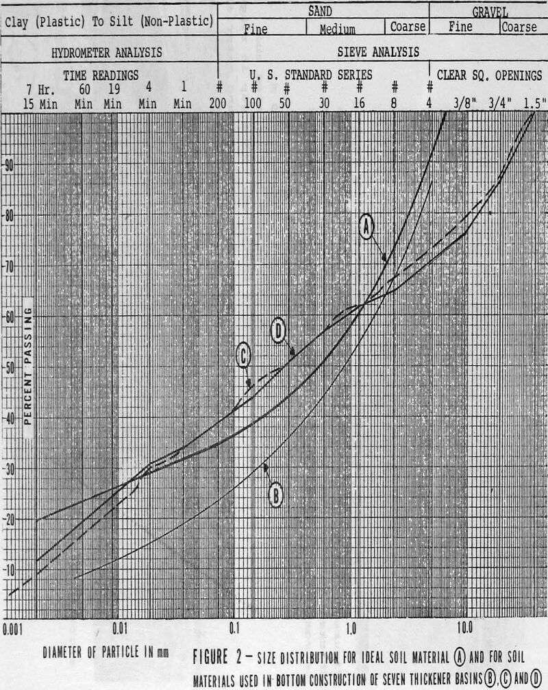
Soil materials selected for seal layer construction will ideally contain 10 to 20% clay, 25 to 40% passing 74 microns and not more than 10% plus 9 mm.
Laboratory testwork on submitted soil samples will develop the following data:
- Optimum moisture content for maximum compacted density.
- Permeability coefficient for cores of untreated soil.
- Amount of soil stabilizer for maximum density.
- Amount of seepage inhibitor required for soil blanket treatment.
- Required amount of seepage inhibitor for water borne treatment.
Following completion of bottom compaction, closure of the ringwall and assembly of rake arms, the thickener is ready for flooding.
Water is pumped to the feedwell launder and the seepage inhibitor compound is concurrently metered by pump into the launder for a concentration of 1000 PPM of compound into the feedwell. Pumping is continued until the water level is at 400 to 500 mm above the bottom ringwall interface.
Alternatively, the compound may be mixed in a water truck and pumped to the launder in a series of batches until the water reaches the specified level in the basin.
Earth bottom thickeners, engineered and constructed as generally described in this paper, are considered to be the lowest cost solution for bottom construction presently available to the industry. In addition to the capital cost advantage, these basins have proved to be watertight structures that provide trouble-free operation for indefinite periods of time.


Design of Scalloped-Bottomed Thickener Tanks
Thickeners are simply large tanks, usually circular in shape, which are designed to allow settling of solids and to operate with continuous overflow of clear water and underflow of thick pulp. The dimensions of the thickener are usually such that dewatering of very fine pulps may be accomplished while still overflowing clear water.
Significant cost savings often can be realized by the use of a scalloped-bottomed tank. The particular scalloped bottom discussed employs radial beams forming the outline of the cone-shaped bottom. These beams are supported directly by columns. Cone segments are hung between adjacent beams. The exact geometry of these segments depends upon the cone angle and radius, the number of radial beams, and their inclination. The geometry is chosen to satisfy certain clearance restraints and to utilize the material as efficiently as possible. The resulting thickness of these segments is significantly less than that of the equivalent plate for the tank with a conical bottom. This result, along with the simpler fabrication procedures required, accounts for the cost savings associated with this design.
In order to predict the stresses and forces that occur in the scalloped-bottomed tank, it is important to have a thorough understanding of the geometry of the structure. The radius of the cylindrical tank is equal to R. The number of radial beams, N, is usually determined by the number of supports deemed necessary and the spacing requirements for ease of access to the bottom of the tank and ease of connection at their common central ring. Typically, N might equal 8 for smaller diameter tanks and become 12 or 16 with increasing diameter. The angle 6, which lies in the horizontal plane, is given by
δ = 2π/N
The radial beams are inclined by an angle β with the horizontal. The length of each beam, L, is then given by
L = R/ cos β
A typical cone segment O-A-B is shown in Figure 3. Point O is the theoretical intersection of the radial beams; points A and B are at the intersection of the radial beams with the cylindrical shell; point M lies halfway between A and B on the straight line joining the two; point C is the lowest point on the intersection curve of the conical segment and the circular cylindrical shell. The length of line A-B equals S and is given by
S = a R sin δ
Internal Scallop Forces:
The pressure acting along line O-C is given by
p = p (h – x tan Δ)
where, p is the density of the contained product, x is the horizontal distance to a point along line O-C and h is the pressure head at point O.
The horizontal component is usually resisted by a compression ring. The vertical component is transmitted through bending in the ring into the columns supporting the tank. Alternatively, the imbalance of the net internal forces from one section to the next along the cone may be considered to be all or partially resisted along the length of the radial beams. This resistance is due to the shearing forces transmitted from the edges of the conical segment to the radial beams. If these forces are properly taken into account, the compression ring may be significantly reduced in size or eliminated completely and the shear in the supporting columns may be reduced.


