According to the statement made above, in a conventional conical cyclone where both overflow and underflow discharges are axial, a free vortex should form. Actually, a combination of free vortex and forced vortex known as Rankine’s vortex forms. It basically consists of two parts as shown in Figure 3: a forced vortex (b) – equivalent to a rotating solid body (rotational flow) – between the vertical axis of the vessel and a radius close to the radius of the vortex finder (a zone where the radial component of the velocity is virtually zero), and a free vortex (c) or potential flow (irrotational flow) between the vortex finder and the wall (a zone with an inward radial component of the velocity). The region with the forced vortex is the central viscous or turbulent vortex region and is defined as a vortex core or viscous core.
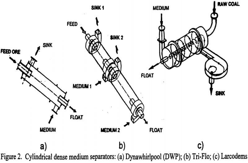
In a cylindrical cyclone, with axial overflow discharge and peripheral underflow discharge, as in the DWP, Tri-Flo and Larcodems, the vortex type approaches a forced vortex when the underflow flowrate prevails (high value of the ratio: underflow flowrate/feed flowrate), it approaches Rankine’s vortex if the overflow flowrate prevails.
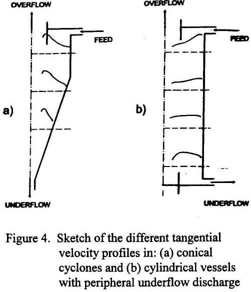
Figure 4 is a simplified sketch of the different flow patterns in conical cyclones and in cylindrical vessels with peripheral underflow discharge, considering the more common operating conditions with high underflow flowrate/feed flowrate ratio for cylindrical vessels. Practically, free vortex conditions (w=k/rn) prevail in the largest part of a conical cyclone, where separation phenomena take place. The motion approaches that of a forced vortex (w= k r) on the medium inlet side for a large part of the cylindrical cyclone.

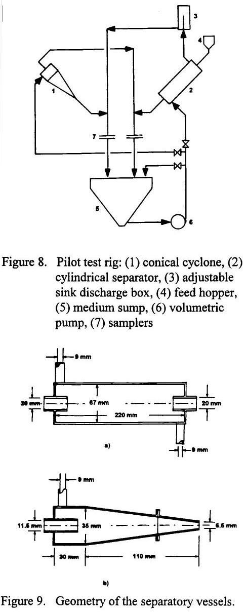
Although the occurrence of Rankine’s vortex has been known for a long time for the conical cyclone, the flow patterns shown in Figure 4 were only partially described in early studies for the cylindrical vessels. They result from the experimental studies that will be described in the following. A pilot test rig was installed (Figure 8) in order to obtain a more comprehensive picture of the different behaviour of dense media in cyclonic devices of different shape. It consists of a medium sump, centrifugal pump, dynamic separator (a conical vessel (DSM cyclone) or a cylindrical one (one stage of Tri-Flo) as desired), as well as sampling devices. Figure 9 shows the geometry and dimensions of the cylindrical and conical separators available in the lab and used in the tests. They do not have involute inlets as industrial units do, but only tangential inlets. We have assumed that this simplified geometry, and the use of small scale units, do not significantly change the general behaviour of suspensions in the separators.

- The tangential velocity profiles in cylindrical separators differ greatly from those in conical cyclones. The fluid motion in a conical cyclone is that of Rankine’s vortex, where free vortex conditions affect the largest part of the vessel. In a cylindrical vessel, the motion approaches that of a forced vortex, i.e. that of a centrifuge.
- The free vortex conditions in conical cyclones give high values of tangential velocity (higher than at the feed inlet radius). This produces very high centrifugal acceleration values in the separation zone (which are roughly inversely proportional to r³) and very strong densifying in a wide range of operating conditions.
- The high values of centrifugal acceleration in conical cyclones produce two opposite effects: they help separation by increasing the mass forces/drag forces ratio, particularly for small particles and viscous media; they also worsen the separation since the high densifying effect produces a high density gradient in the separation zone.
- The forced vortex conditions in cylindrical cyclones give lower tangential velocity values than those at the feed inlet radius. This produces lower centrifugal acceleration values in the separation zone (which are roughly directly proportional to r) than those values in conical cyclones. However, at the same time, the densifying effect is also largely reduced, as well as the density gradient inside the vessel.
- It is commonly thought that in cyclones, the higher the centrifugal acceleration, the more efficient the separation. However, this may be true only in some cases and for some applications. In dense medium cyclones, excessively high tangential velocity values may be harmful since the growth or strengthening of recirculation regions could make some particles reentrain into the wrong flow, and the increase in the density gradient inside the separator could be deleterious. The Tri-Flo would also not be likely to improve its separation when the fluid velocities are increased above a certain limit for the above mentioned reasons, and since increased turbulence levels might disturb the transport of particles.
- There is a wide-ranging opinion that the high densifying effect is particularly detrimental because: (i) it gives a high density differential (density difference between sink and float media) and hence a high density gradient in the separation zone; (ii) it causes an accumulation of medium solids in the cyclone, thus increasing the density cut-point over the feed medium density. This last point is considered harmful for separation sharpness since a variation in densifying causes instability of the density cut-point. Recently, some authors have pointed up this fact, suggesting the use of dense medium dynamic processes working at near “zero offset” conditions (density cut-point = medium density); this may possible with cylindrical vessels such as the Tri-Flo. In many cases, the poorer separation produced by the high densifying effect overrides the benefit of the high centrifugal acceleration, and this explains the recent trend towards dynamic DMS processes working near “zero offset” conditions.
- The axial velocity profiles of conical and cylindrical cyclones also differ because the transition of the axial velocity profile between the upward and downward flow regions is sharp in conical cyclones. Instead, it is gradual in cylindrical vessels, with a wide zone where the axial velocity is zero or near zero, a feature that should improve separation.
- Consequent to the different velocity profiles, the performance of conical and cylindrical vessels differs in various applications. For classification, thickening and clarification, conical cyclones are more suitable and therefore are normally used. For dense medium separation, cylindrical vessels reveal some advantages over conical vessels, so they should be preferred when installing new plants.
- In accord with the results of this study, industrial use of the Tri-Flo, cylindrical dynamic dense medium separator, has proved that efficient separation can be obtained even in case of very difficult problems, where conical cyclones have failed, e.g., upgrading lithium and feldspar ores.

