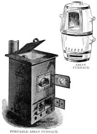
 In the early stages of opening up a mine, when there is some uncertainty as to its future career, necessitating caution in laying out works of a permanent character, the want is often felt of an assay furnace, easily built and easy, of transportation, should the “ mine ’’ prove to be “ no mine.” Again, cases occur in which parties buy the right to treat comparatively small heaps of tailings, treat them, and then shift their plant to other localities. Under these circumstances it is necessary to restrict the plant to the barest necessaries, to suit, so to speak, the nomadic character of the work.
An assay furnace that is really portable, easily transported, erected, taken down, of little weight, always ready for action on short notice, is indeed in these cases a desideratum which has long been wished for. The gasoline furnaces introduced into the Australian market some time since practically fulfil these conditions ; but they have the fatal drawback of being dependent on a constant supply of the liquid fuel, gasoline, which is seldom, if ever, obtainable locally in any wayback mining township, and has, consequently, to be ordered a long time beforehand, and has often to be carted hundreds of miles per bullock team or other such means, so that there is always a certain amount of chance of being stopped for want of fuel.

It occurred to the writer that if it were possible to substitute a hydrocarbon easily procured at a low cost, the furnace and appurtenances could perhaps be modified sufficiently to suit the new fuel. The question, therefore, resolved itself whether kerosene could be brought to do the work of gasoline. On an actual trial under normal working conditions it was found that with trifling alterations, the ordinary gasoline burner would give quite satisfactory results with 150° fire test kerosene. Accordingly a trial extending over several months of fairly frequent work, and under all sorts of possible conditions, was entered upon, with the results now to be set forth.
The ordinary outfit for a gasoline furnace consists of a reservoir, in which the gasoline is poured through a hole afterwards made air-tight with a screw-plug and leather washer. To the reservoir an air pump, much the same as a bicycle pump, is attached, connected through a check-valve to a pipe leading inside the reservoir and delivering the air pumped in, above the surface of the gasoline, creating a pressure in the vessel and forcing the liquid along the outlet pipe leading from the bottom of the vessel to the burner. The burner or vapourizer consists essentially of a pipe bent on itself in such a way that the vapourized liquid issuing from the outlet partly impinges on the pipe itself, thus part of the heat, produced goes to vapourize a further supply of gasoline. At the start an initial amount of heat, sufficient to vapourize a little of the gasoline, has to be supplied from some outside source, and this is generally provided by burning a little gasoline in an open vessel under the burner. The amount of gasoline burnt, and thus the amount of heat generated, is regulated by a needle valve closing the orifice from which the vapour is issuing. It should be stated that the jet of vapour, issuing with considerable velocity, is made to draw in a quantity of air, on the same principle as a Bunsen burner for ordinary coal gas, and thus perfect combustion is insured. The burner, as manufactured in America, under the Hoskins patent, consists of a single casting of brass in which a system of holes is bored in straight lines, intersecting each other, so as to form a continuous passage for the gasoline or other liquid, the holes on the outside of the points of intersection being stoppered by screw-plugs of brass, thus giving opportunity for an occasional cleaning. The liquid fuel enters at the lower end, where it joins with the supply pipe from the reservoir, thence horizontally to the front end of the burner, which, exposed to the radiating heat from the furnace when in operation, gets red hot, and thus converts the liquid into a gaseous fuel. From the front the vapour travels along another passage at the top of the burner to the back of the burner again, thence downwards to the valve chamber, from which it issues in a horizontal jet, through a wide passage having free communication with the air, with which it is mixed in the necessary proportions, and on leaving the burner it enters the furnace orifice as an intensely hot pale blue flame. In the lower duct of the burner several lengths of copper wire are introduced and left loose, presumably to conduct some of the heat from the hot to the cold part of the burner.
In substituting kerosene as a fuel, these wires are taken out, as, owing to the temperature of the front of the burner, kerosene deposits carbon in the passages through which it travels, and the wires in question help to choke them, which is the greatest fault to be found in the use of kerosene. It, however, does not amount to a great deal, and to overcome this defect it is sufficient to take the screw-plugs out and clean the inside of the passages by inserting a small wire brush, or a bent and flattened wire, finishing the cleaning by pouring a little kerosene through the passages, so as to wash out the last traces of the sediment. The whole operation will not take more than ten minutes, and should be done before heating the furnace.
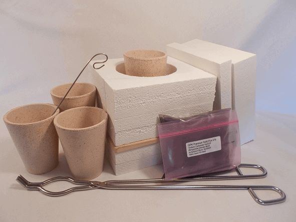
The form of furnace found the most satisfactory for use with kerosene, consists simply of a nail-can twelve (12) inches in diameter and sixteen (16) inches in height, lined with fire-clay. This will take four H crucibles, The fire-clay at the sides is uniformly half (½) an inch from the sides of the crucibles.
In the side of the can, near to the bottom and below the platform, upon which the crucibles rest, is a hole about four (4) inches in diameter at the opening, extending nearly across the furnace. A slit in the upper part of the hole one inch wide and running the full length of it provides communication between this hole and the crucible chamber.
A fire-clay tile of suitable shape for a cover to the can also provides, a good deal of radiated heat to the parts of the crucible that the flame does not touch directly.
The heat generated with kerosene is all that could be desired, and the writer has never had any trouble in obtaining a satisfactory fusion with all sorts of charges.
How to Build a Portable Fire Assay Furnace
The hottest zone in the furnace is the farthest away from the burner, so that the two crucibles farthest away will run down first. In practice, starting with four crucibles in the furnace, the two farthest from the burner are poured when ready, shifting the two nearest ones to the place occupied by the two just poured, and then putting two fresh ones on the places rendered vacant. Thus the crucibles are put in a comparatively cool place, where the charge will quietly run down, then they are shifted to a hotter place till ready to pour. Owing to the gradual application of the heat there is little risk of a crucible cracking in the fire. The writer has run down on several occasions small bars of gold, the heat being sufficient to give a perfectly satisfactory melt in a few minutes. The muffle furnace does not differ essentially in contraction from the melting furnace. The flame is made to travel along the bottom of the muffle, where it splits in two and goes around each side of the muffle and meets at the top, and the heat generated is more than sufficient to do any ordinary muffle work that an assayer is likely to have.

Users of gasoline furnaces are recommended by the makers to connect the muffle furnace with a chimney, or otherwise create a draught in the muffle for oxidizing purposes. The recommendation has not been found quite satisfactory. In spite of the draught, reducing gases from the combustion of the kerosene appeared to be injected into the muffle through the slit at the back, and cupelling became very slow in consequence. The lead in the cupels is often quite hot—hotter, in fact, than is necessary or advisable— and yet its surface keeps still and perfectly bright; but as soon as air is forced into the muffle with a small bellows, or even by blowing towards the mouth of the muffle through a bit of glass tubing, oxidation proceeds rapidly. The conclusion was come to that communication must be cut off altogether between the muffle and the heating part of the furnace, and an independent draught through the muffle created. The slits in the muffle were stopped with fireclay and a hole bored in the top of the muffle at the back, about one inch and a quarter in diameter; in this hole rested the end of a pipe (a piece of common one-inch iron steam pipe) about six feet long, leading upwards and through the roof of the building, to which it was secured, so as not to put any weight on the muffle itself. The plan answered perfectly; the draught was found to be ample—in fact, it had to be moderated somewhat, and it did not seem to affect in the slightest degree the heating efficiency of the apparatus. Another consideration that led to the adoption of the pipe communicating from the interior of the muffle to the exterior of the assay building, was the necessity of getting rid of the lead fumes produced in cupellation—not a trace of them was ever perceptible after the pipe was installed.
In the matter of portability, the melting furnace only weighs about 50 lbs. complete, the muffle a little less, while the reservoir and burner only add eight pounds (8 lbs.) to the weight, so that the whole outfit weighs less than one cwt. The furnace can be started anywhere and at any time at a minute’s notice, and the furnace will reach a smelting heat in from thirty (30) to forty-five (45) minutes.
In conclusion, no claim to anything new is made, the principles of the liquid fuel burners being long well known. It is desired merely to explain a few points about a little-known furnace with which the writer has had considerable experience, and which has undoubted points of advantage over the usual type, under certain conditions.
