Table of Contents
The information below is provided as representative of medium HP Diesel engines of four, six, and eight cylinders. Many other sizes and types are available and variations on four, six, and eight cylinder engines, such as in stroke, bore, and displacement—giving higher or lower HP ranges, may be obtained.
Performance Curves are for maximum, rated, and continuous performance of power units with full equipment, including radiator fan. Full equipment, as utilized in determining data as shown, include air cleaner, lubricating oil pump, fuel transfer pump, fuel injection pumps, jacket-water pump, and a suitable governor.
Fuel Consumption Curves are the fuel consumption of power units with full equipment, including radiator fan, and at various governed speeds. Fuel consumptions shown were obtained with fuel oils having 45-50 Cetane value, 30-34 A.P.I.
The Brake Mean Effective Pressure for a given load and speed can be computed for four stroke cycle engines by use of the following:
B.M.E.P = 792,000 X B.H.P Load/Cu. In. Displacement X R.P.M
Output in Metric B.H.P. (Cheval Vapeur) = Values from Curves X 1.0139
Fuel Consumption per Metric B.H.P. (Cheval Vapeur) = Values from Curves X .9862
gravity (at 60° F.), 33-42 viscosity (S.U. at 100° F.), and a total (gross) heat value of 19,000 B.T.U. per pound, and are based on standard British and U. S. B.H.P.
The maximum output curves show the maximum output in B.H.P. which the engine can develop with a clear exhaust, usable only on intermittent service applications such as excavators, locomotives, hoists, etc.
Rated output curves show the load in B.H.P. which the engine is capable of carrying for a period of 12 hours from each cold start—generally for 12 hour per day service.
Continuous output curves show the maximum recommended load in B.H.P. for continuous day and night runs for more than 24 hours. The continuous output does not exceed 90% of the rated output.
The margin of capacity of the units whose curves are shown is such that during a 12 hour run at rated output and after the jacket-water and lubricating oil temperatures have become constant, the engine is capable of carrying a load of 10% above its rated output for one hour without undue heating or mechanical trouble—and then continue with its 12 hour rated load. Output figures and references are based on a sea level barometric pressure and a standard temperature of 60° F.
Foundation prints, specification sheets, performance and fuel consumption curves, altitude derating curves and other detailed information will be supplied on request.

Diesel Engines
Advantages and Disadvantages of 2 and 4 Cycle Engines
Advantages
2-cycle: (a) Power developed by piston displacement per unit of volume, 75% to 90% more than a 4-cycle engine.
(b) More even crank effort.
(c) No air inlet valves, no exhaust valves.
4-cycle: (a) Lower fuel consumption.
(b) More complete combustion of fuel.
(c) Possibility of use of lower grade fuels.
Disadvantages
2-cycle: (a) Inferior combustion of fuel and a therefore smoky exhaust.
(b) More cooling water required and more oil for lubrication.
(c) Greater fuel consumption.
4-cycle: (a) More pounds per horsepower.
(b) Air-inlet and exhaust valves requiring valve motion which results in extra wearing parts.
(c) Unsteady crank effort requiring a heavier flywheel.
Speed
As a rule Diesels are classified as to speed by rotating speed and average piston speed in feet per minute, but neither of these in itself is entirely descriptive as an engine with say a piston speed of 1000 feet per minute could rotate at 200 rpm., in which case it would probably be classed as a medium speed engine, but if the same engine had an rpm. of 800 it would then be classed as in the high speed class.
Diesels are therefore classified as being Low, Medium, High or Super-high Speed and it requires a combination of both rpm. and piston speed to determine in which speed range they come.
Horsepower
Commercial engines are available in sizes from 5 HP to approximately 25,000 horsepower.
Combustion Systems
A. Air-injection: fuel is blown into the cylinder and atomized by air in the neighborhood of 900 to 1300 pounds per square inch pressure.
B. Solid-injection: fuel is precompressed to 900 to 6000 pounds per square inch and is then atomized by passing it through one or more small injection orifices.
The table listed following gives a general idea of the sizes which are usually adaptable to use by the smaller mining companies for use as prime movers or in other words drives for ball mills, crushers, etc., or they can be direct connected or belted to generators which in turn furnish electric power for the operation of these ball mills or crushers.
No attempt is made here to cover the very large Diesels ordinarily classed as stationary. They would require special tables and if information on any certain size or type is desired this information can be furnished on request.
The brake horsepower and weights shown on the table vary slightly depending upon the accessory equipment supplied.
Diesel engines can be furnished with various attachments such as, electric controls for regulating engine speed, heat exchangers, mufflers, (for industrial silencing) air-cooled oil coolers, and safety devices for shut-down of the engine in case of low oil pressure or excessive water temperature.
Diesel Electric Sets
Diesel Electric Sets are complete units consisting of a Diesel Engine directly connected to any of several makes of direct or alternating current generators. They are available in many sizes using an externally regulated generator or a self-regulated generator.
The electric sets may be paralleled with each other and with other generators with similar operating (voltage) characteristics.
Generally speaking Diesel engines may be classified as:
1. (a) 2-cycle, (b) 4-cycle.
2. (a) Horizontal; (b) vertical; (c) radial.
3. (a) Single acting; (b) double acting.
4. By speed.
5. By horsepower.
6. (a) Air injection; (b) solid injection.
Cycles of Operation
All of the more commonly used Diesels operate on either of the following cycles: 2 cycle where the cycle consists of two strokes of the piston (a) expansion; at the end of the expansion stroke, exhaust ports are all uncovered by the piston, burnt gas is discharged and pure air enters the cylinder, (b), compression which closes the exhaust ports; and fuel is then injected just as compression is completed.
In the 4-cycle engine the process is completed in 4 strokes of the engine, (a) Air Inlet, (b) Compression. (c) Expansion, (d) Exhaust.

Electrical Data


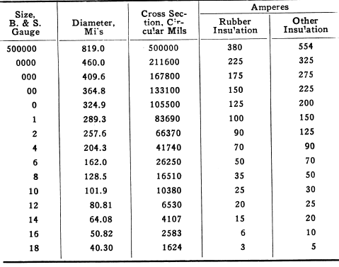
Allowable Carrying Capacities of Copper Wire

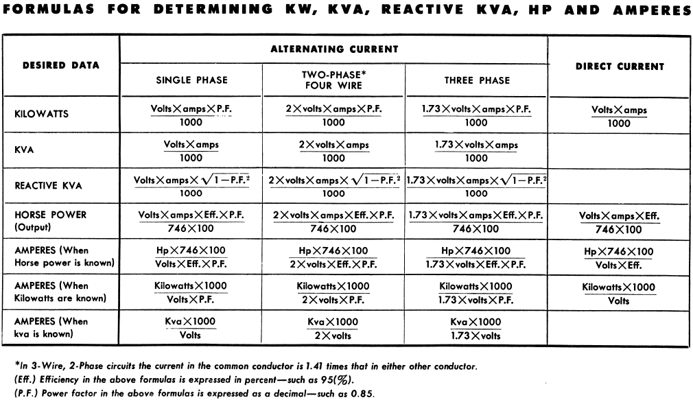
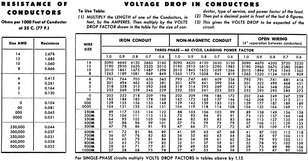
Electrical Conductors
The above sizes are those commonly used through-out the electrical industry, mills, mines, etc. Sizes are selected for a given motor or piece of electrical equipment, from the Name Plate Rating on the equipment to which lines are connected.
The above table, standard throughout the world, gives the sizes of conductors which will carry the current as listed without undue heating. A SAFE WIRE FROM A FIRE STANDPOINT.
For any electrical installation the necessity of considering the most economical size wire should be given much study. The most economical conductor to use is one in which the annual cost of energy loss is equal to the interest and depreciation charges on the conductor—copper or aluminum.
To calculate the proper sized wire it is necessary to know (1) Amount of power, (2) Cost of power, (3) Hours of operation, (4) Cost of conductor in cents per pound, (5) Interest and depreciation charges.
Example: A continuous operation, such as a mill, smelter or other industrial plant using power twenty-four hours per day, 8,760 hours per year, with a power cost of .0125 cents per kilowatt hour, 20% interest and depreciation charges, with copper conductor costing $.25 per pound, use 2,750 circular mills per ampere of current. Aluminum conductors costing $.25 per pound, use 6,400 circular mills per ampere of current. Where the load factor is low, power costs are greater, hence with an operation on an eight-hour-per-day basis, approximately the same wire sizes are required.
Notes: The circular mills of conductor per ampere and the cost of conductor per pound, are fixed. Voltage has nothing to do with the problem. The wire or cable has to have suitable insulation for the location and service where used. Insulation of conductor, wire supports, conduit, and building that supports the wire are not a part of the electrical circuit. There are no electrical losses in these. The wire conductor itself is the only part that carries the current, the only part in which losses occur. It is common to find wires carrying so much current that the losses per year will often equal the cost of the conductors many times over.
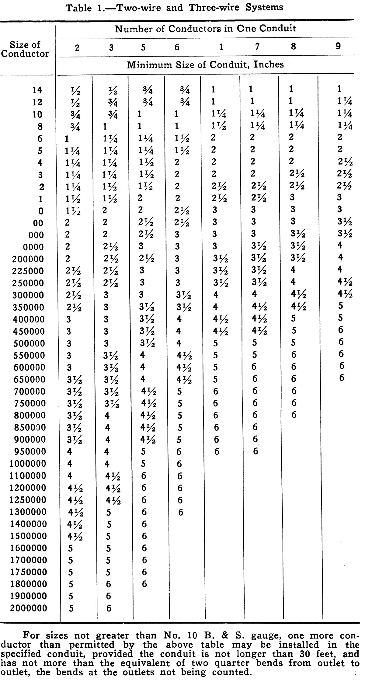
Size of Conduits for the Installation of Wires and Cables

Source: This article is a reproduction of an excerpt of “In the Public Domain” documents held in 911Metallurgy Corp’s private library.
