In 1971, during the planning and design stages of a $300 million expansion, the Iron Ore Company (I.O.C.) of Canada Ltd. through its Engineers, Canadian Bechtel Ltd., came out with a preliminary request for two 10,000 LTPH belt conveyor scale systems. These Systems were to provide weighing accuracies within ±.5% of the iron ore pellets and concentrates in transit on two 72″ wide conveyors from the stockpiles to the ships. Each conveyor system would be fed by a rail mounted bucket wheel reclaimer, with the conveyed material moving directly to the ship loaders with no intermediate surge and/or storage bins between the stockpiles and the ships.
After initial discussions with various belt scale manufacturers, I.O.C., Bechtel and Mr. Colijn decided that what they wanted was not an “off the shelf” item and it would have to be a joint engineering/development effort between I.O.C., Bechtel and the Supplier, so a Supplier should be selected rather than a specific product. On the basis of our presentation of applying electronic track scale techniques and equipment both in terms of the electronic measuring equipment used and the weigh bridge design, we were selected as the supplier.
The system design stage took approximately 4 months encompassing over 100 meetings plus 1 trip to Sweden to look over the LKAB Systems at Narvik, Norway, Lulea, Sweden and Oxelosund, Sweden. The final engineered System that was jointly approved was as per the following:
- Two 72″ wide horizontal conveyors equipped with gravity take-ups. One conveyor was 533′ long, the other one 885′ long.
- The conveyors would use fabric belting, – Specifically, the belting selected was a 2 ply UniRoyal Useflex 800 having a ½” top cover and 3/16″ bottom cover, with an operating tension rating of 800 lbs/in/width.
- 45° catenary impact idlers are to be used between the feed points and termination point eleven idler spaces prior to the centre line of the scales. 35° fixed idlers are to be used on the weighbridge and the approach/retreat sections of the scales, with 35° catenary idlers used from each scale retreat assembly to the head pulley.
During this time, the end user (I.O.C.) also firmed up their specifications as per the following:
(a) System accuracy to be within ±.5% of load between 10% and 100% of the belt capacity.
(b) System to have demonstrated repeatability during calibration of ±.1% from 20-100% capacity.
(c) System to have a bilingual (French-English) alpha/numeric printout device to display bridge load rate; total LT; and be equipped with typewriter – style key-board
(d) Calibration weights are to be used, calibration chains will not be considered. Weights to simulate 33%, 66% and 100% belt loading.
(e) Scales are to be checked by material load tests using railroad track scale weighments as the reference weights.
(f) Some means of belt speed control to automatically control the speed as to try and maintain a fairly consistent belt loading, given the erractic loading patterns of the bucket reclaimers.
We tried to waive the variable speed controller aspect of the specification, but were unsuccessful. Our thinking was that the belt tension variations due to introduced belt speed changes, would have similar or worse effects on the weigh signal than the loading variation themselves.
The function of each controller is:
(a) to accept a control scale signal from a single idler scale located on the belt preceding the weigh belt and automatically control the speed of the weigh belt to maintain a reasonably constant lbs/ft. loading by automatically selecting one of five pre-set speeds representing 20, 40, 60, 80 and 100% of maximum speed.
(b) To provide above outputs such that a belt could increase its speed from its present range to the required range within the same acceleration time. (i.e. 20-100%.speed within the same time as 20-40%).
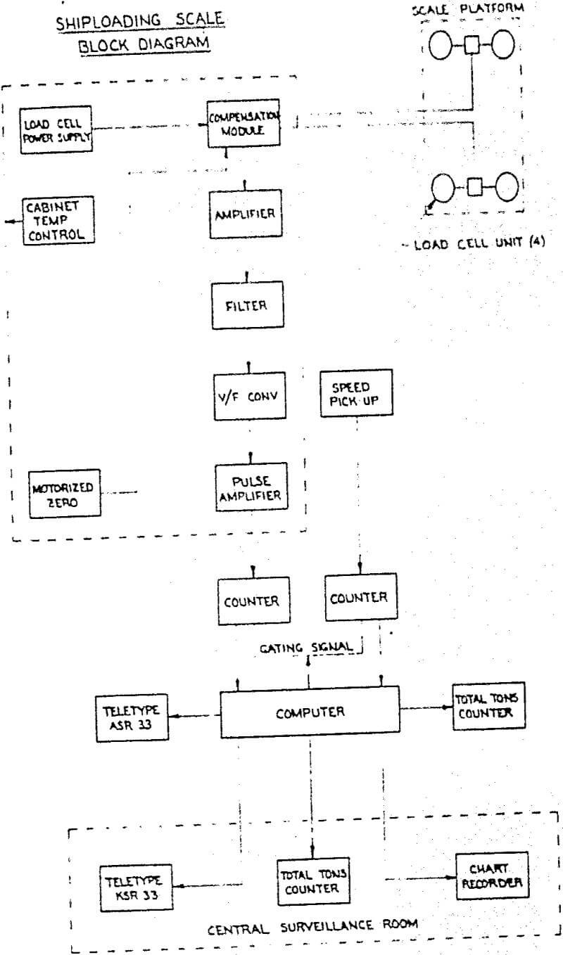
Electrically, the System comprises the following equipment.
- Load Modules – (Four (4) per Scale)
- Environmental Cabinets: (One per Scale)
- Compensation Module
- Load Cell Power Supply
- Mechanized Zero Module
- Strain Gauge Amplifier
- Filter Module
- V/F Converter
- Computer Module


