Table of Contents
Small mines are almost invariably adit rather than shaft mines, and in most instances ore is trammed directly from mine to coarse ore bin at the mill for crushing. Accordingly, most mills are situated adjacent to the portal of the main haulage level. In a few cases, location of the mill at the mine is impractical due to water shortage, adverse snow conditions, inaccessibility, etc., and therefore a wide choice of mill sites may not be available. Careful consideration of all the economic factors is a prerequisite.
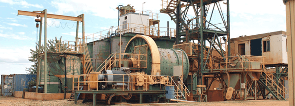
Requirements for Mineral Processing Plant Design
Preliminary to mill design the mine must be developed to the point where a decision may be made on daily mill tonnage, and representative samples can be obtained for metallurgical test work. From the metallurgical test work a flowsheet is worked out and the mill site is then selected.
When the mill site is selected, and cleared, a detailed contour map of a reasonably broad area around the mill location is required so that full consideration may be given to access roads, tailing disposal, water supply, and service facilities. Test pits for foundation information must be dug in most cases. The next step is completion of a preliminary layout based on the selected flow-sheet and mill site contour. This is followed by determination of all machinery sizes so that manufacturers’ drawings can be obtained as quickly as possible.
With the above information final elevations can be determined and mill foundations designed. Following this, the building and installation programme is quite straightforward.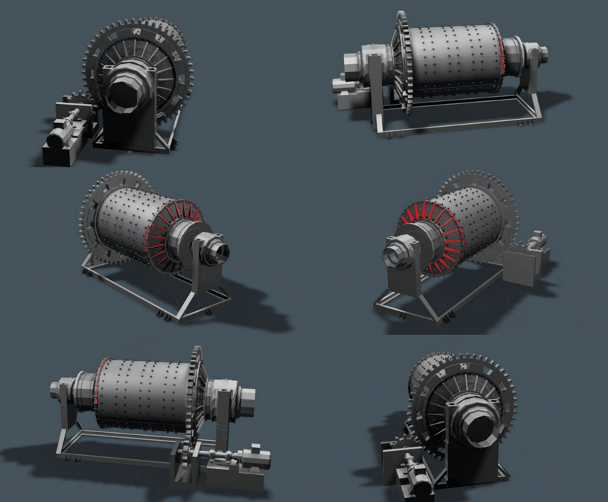
Construction of Small Concentrating Plants
The following remarks are generally applicable to the six plants referred to in the present article. These plants are of standard frame construction on concrete foundations. Lumber, other than truss lumber, is obtained from the nearest available sawmill, cut to size and length as instructed. To obtain added strength for the building wall frame, the exterior shiplap is placed diagonally. This is found particularly necessary for the ore bin tower framework.
The trusses frequently are prefabricated and shipped to the site knocked down in crates and marked for assembly. Depending on the spacing of the trusses or roofing frame, the sub-roof is shiplap or in 2-in. material. Roofing is generally ready-made roll-roofing or aluminum sheeting. In heavy snow country, where most of the mills are located, the pitch of the roof is made 8 in 12, with the aluminum roofing preferred, as the heavy snow load slides off the roof with the added warmth of the building interior. The overhanging eaves are completely housed on the outside with the heated air allowed to circulate to this space. This prevents ice forming above the eaves and minimizes formation of icicles.
The exterior finish to the walls will vary, with about three types to choose from, these being ordinary building paper, ‘ready-roofing,’ or ‘asbestoside.’ All sash and doors are usually primed at the factory and the desired finish colour added when in place.
A feature of each mill is the octagonal laminated construction of the coarse ore bin, which is totally enclosed to protect the ore in the bin from freezing. The fine ore bin is usually a wood stave tank, again with a building frame totally enclosing it. The twin concentrate bins are raised high enough to afford clearance for a truck and are emptied through the bottom by means of removable floor sections.
All heavy mill equipment is set on reinforced concrete foundations carried down to solid bearing. Lighter machinery is supported on wood frame substructure. Concrete floor slabs are sloped to desired points, particularly the subfloor below the flotation cells to a collecting trough and in turn to sump and pump.
Changes in floor levels are made with easy stairs to the various levels. The reagent platform is sufficiently high to provide adequate man clearance beneath and to provide gravity feed from the reagent feeders to any position. Guard rails 3 ft. 6 in. in height are always placed between changes in levels.
Power Supply
Owing to the remote situation of most of the small mines, very few are within economic distance of the transmission lines of any existing power company. Accordingly, most mines must provide their own power supply. Because of the mountainous terrain, the choice is frequently available between hydro-electric and diesel-electric installations. At small mines with limited ore reserves, however, the choice is almost invariably in favour of diesel-electric, because of the much lower capital cost. In addition, the salvage value on a hydro-electric installation is limited, whereas a diesel-electric installation can be readily transported for re-use.
Of the six plants discussed in the present article, five are powered by diesel-electric and the other has a hydro-electric installation. There are many economic factors involved in this hydro-electric installation and while the capital cost is undoubtedly higher than for equivalent diesel-electric, the hydro-electric installation is relatively straightforward. In addition, the mine is difficult of access and therefore transmission of power to the mine from the centrally-located hydro-electric station offers advantages.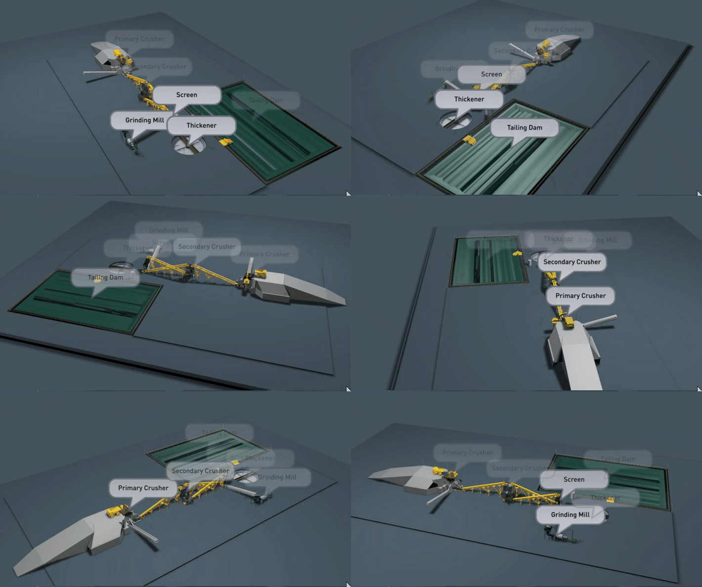
The usual’diesel-electric installation is housed in a building adjacent to and connected to the mill building proper. The disadvantage of this adjacent location is, of course, the risk of fire and the consequent higher insurance rate, but this disadvantage is more than overbalanced by the following advantages:
- Waste heat from the diesel-electric plant is readily available to the mill.
- Surplus hot water from the cooling system is of advantage in the mill for increasing the temperature of the flotation pulp.
- In a small mill, supervision of the power engines can be handled by the mill crew without increasing the number of employees and this economy, amounting to three man-shifts per day, greatly outweighs the added insurance costs.
Power costs vary from less than 1 cent per kWh for purchased power from utility companies to more than 4 cents per kWh for diesel-electric power.
Electrical Installation
Electrical installations are usually let out for contract bid and since this is one of the last jobs to be done in a mill installation, the time saving advantage of having a contractor with fairly large electrical crew is important. Electrical installations are quite straightforward in most cases, consisting of a diesel-electric plant requiring a synchronizing panel, main disconnect switch, and two main distribution panels, one for the mill proper and one for the crushing plant. Combination magnetic switches with stop-start buttons are usually employed with a remote stop-start button at the machine to fulfill safety requirements.
Lighting
Lighting is standard, with the exception that fluorescent lighting is usually provided over the flotation machines. This lighting is kept at a fairly high level so that the influence of daylight, does not affect the operator’s judgment on the appearance of the froth.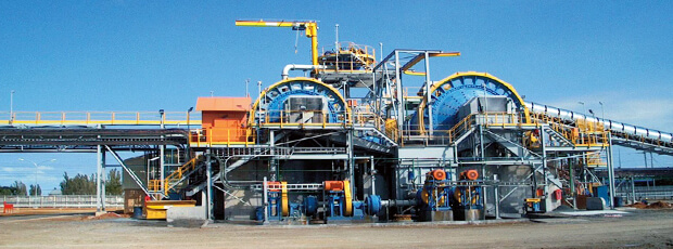
https://www.911metallurgist.com/mobile-ore-processing-beneficiation-plant
Features
Several features are incorporated into the plants under discussion. In general, these aim at decreasing costs without Sacrificing efficiency, and are also adapted because of local conditions. Briefly, they are as follows:
Flood Feeding—This system, based on feeding from the face of the coarse ore bin only, gives a lower proportion of live capacity in the bin than does bottom feeding, but requires less headroom and results in almost automatic feeding. This system allows the use of a heavy-duty coarse ore belt-feeder instead of the most expensive pan feeder. The feeder is installed under the coarse ore bin. The extension from the bin face is built up with high side boards to prevent spillage. The rack and pinion gate over the opening is kept open except in emergency. Therefore, there is a flood feed on the belt at all times with the gate controlling the angle of repose on the belt to prevent overflow over the discharge. The belt is never empty and thus the ore, and not the belt, absorbs any direct shock when the bin is filled. Rate of feed is controlled with a stop-start push button and/or variable drive.
Vibrating Screen.— It has been found beneficial to use a vibrating screen instead of the conventiorial stationary grizzly. This is especially applicable in single-stage crushing plants. The main benefit derived is the positive removal of primary fines ahead of the jaw crusher, which allows a closer setting and therefore a better and more uniform feed to the ball-mill, with corresponding tonnage increase. In two-stage crushing plants vibrating screens are invariably used ahead of the secondary crusher.
Grinding Circuit.—Standard single-stage grinding circuits are the general rule, with operators favouring the spiral classifier because it is not necessary to drain after forced shut-downs. In one instance a jig is used in closed circuit with classifier and ball-mill for recovery of coarse native silver. At another plant a unit cell is employed for recovery of coarse silver-lead concentrate to assure a uniform grade of feed to flotation, to increase recovery and to improve filtering.
Flotation Reagents and Concentrate Pumps.—The flotation floor is laid out for compactness and where possible has one operating aisle. The aisle is set at a height to allow easy cell adjustment. The launders are built so that the cleaning stages can be varied as required. Allowance is made for stage-feeding reagents from mechanical feeders whether dry or wet. Concentrate pumps are frequently preceded by small tanks to absorb surges and to take care of filter overflow, especially when direct filtration is employed. The flotation floor is usually set well above the mill floor, with concentrate pumps below and ample drainage to mill sump.
Dewatering.—In small mills there is a definite trend to direct filtration or dewatering without thickeners. As most plants of this type are handling relatively coarse grind ores, direct filtration of concentrates gives a low moisture content. The saving in capital cost for thickeners, diaphragm pumps, and larger buildings is considerable.
Wet Vacuum System.—A wet vacuum system instead of the conventional dry system is occasionally used. This results in an appreciable saving in capital equipment and installation costs, as the customary filtrate pump, filtrate receiver tank, moisture trap, and considerable piping are eliminated. The wet cycloidal vacuum pump is on the gravity discharge of the filter. It requires about 20 per cent more power with approximately equal results.
Concentrate Handling.—The capacity of concentrate storage facilities is in general dependent on distance from the railroad. This storage usually consists of a concentrate bin or bins with filter above. Bins are built so that a truck can pass beneath and loading is usually by hand from removable floor planks in the bin bottom. Louvres on the bin face allow for initial discharge of the bin. One plant loads with a small electrically-driven slusher.
Storage.—Ore storage in the coarse ore bin and the fine ore bin is designed to meet the requirements of the customary 5 days per week mine operation and 7 days mill operation. Fine ore bin capacity is such that the crushing plant can usually shut down one day each week. General practice is to do all crushing on one shift for three-shift mill operation. Concentrate storage is arranged on the same basis and allows for haulage distance. Because of the distance from sources of supply, storage facilities are usually provided within the mill proper for ample quantities of reagents, grinding ball, spare parts, liners, etc.
Controls, Laboratory, Sampling.—Because of the small size of the plants under discussion, mechanical metallurgical controls are not generally used. Density and pH readings are taken at regular intervals and grind control is by periodic screen analysis, while tonnage determinations are usually by means of 3 time-sample from the fine ore feeder. Sampling is generally done by hand-cutting methods, but in some mills an automatic sampler is used on the tailing. Assaying is usually on a shift basis. The assay office is in a separate building where fire assaying is employed. When only wet assays are required the facilities are sometimes housed in the mill proper.
Tailing disposal.—Tailing disposal is usually by gravity to a nearby flat site for impounding. Impounding is necessary because of fish and game regulations and/or small power plants on the same water system. In no instance is tailing impounded for water recovery.
Operating. Crew.—There are two men employed on each shift in the concentrating section. When the power house is adjacent to the mill, the mill crew operates this portion of the plant with the assistance of overall supervision from the company master mechanic.
Heating.—Heating methods vary from dependence on an adjacent power plant for radiated heat to hot air coal-fired furnaces, to waste heat recovery by water tube boiler on diesel exhaust gases, or to circulating hot water systems with unit heaters, or oil-fired unit heaters.
Safety.—It is standard practice to have a dust exhaust system in the crushing plant. An exhaust fan is connected to the dust concentration points at the crusher, screen, etc. The equipment is housed in as far as is practical. Water sprays are also used and dust counts are taken periodically by a Government inspector.
All walkways, stairs, platforms, etc., are properly guarded with suitable railing and V-belt drives have safety guards. Oil and grease line extensions are used to avoid hazards.
Electric wiring is to Government specifications and all wiring is in rigid metal conduit, switch boxes, motor frames, and electrical panels being grounded. Stop switches are adjacent to all motors where emergency stop or starting supervision is required.
First aid kits are provided and instructions for first aid treatment for injuries are at hand.
In mill design, care is taken to arrange the layout to facilitate good housekeeping, which assures safety.
