Table of Contents
In classification of pulps bearing magnetized ferromagnetic particles, depolarizing is of great importance. If size separation is to be effective, particles must be individual rather than in flocs. Depolarizing is also practiced in heavy medium separations in which ferrosilicon or magnetite is the medium.
Properties of Ferromagnetic Materials: Experimental work, described below, has shown that if a sample in the magnetized state is heated above the Curie point and cooled, much of the preferred orientation is destroyed and the sample is substantially depolarized. It has been thought that when the sample cools below the Curie point the domains cancel each other, leaving a zero net moment. However, such particles still exhibit a tendency to cohere, and undoubtedly this is caused by the forces of residual magnetism.
Mechanism of Depolarizing with Alternating Current Magnetic Fields: It is believed that when ferromagnetic material is passed through an alternating magnetic field, depolarizing occurs in the decaying portion of the field. As the particles pass through the portion of highest intensity they become magne-

tized. If the particles are not free to move, the polarities of the particles will be reversed (by a mechanism similar to that described above for magnetism) at a frequency equal to that of the applied field. As the material moves through the decaying field, intensity levels become such that a domain does not completely reverse, but stops on an axis of easy magnetization.
Experimental Work
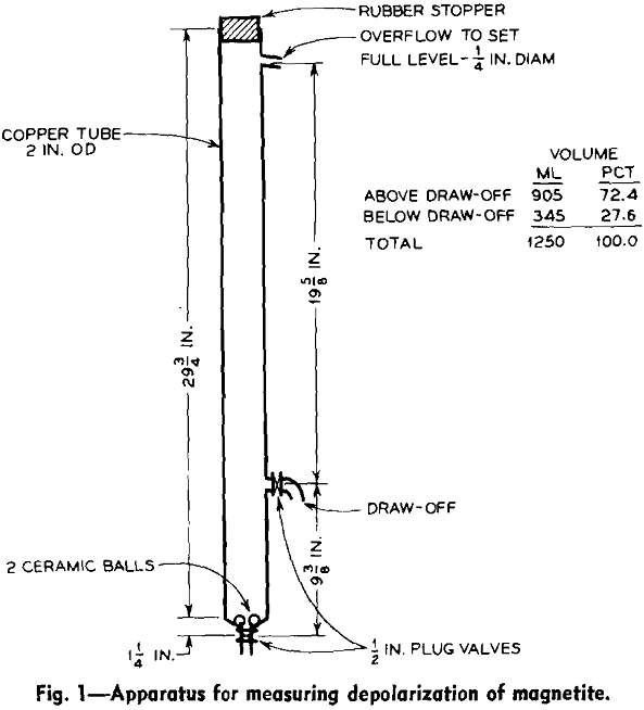
Evaluating Effectiveness of Depolarizing: Evaluation methods previously used were unsatisfactory for this work because gangue particles made it difficult to observe the settling rate of the magnetite. To overcome this objection, modifications were made to measure settling rate of the magnetite only. With this method the criterion of depolarizing was the slow withdrawal from an 800 oersted (rms) a-c field. The present work substantiated the findings of Hartig that slow withdrawal from a field of 550 oersteds or more was equivalent to depolarizing by the Curie treatment.

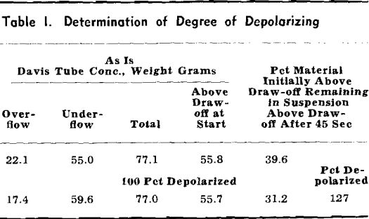
At the end of the sedimentation period the draw-off plug valve is opened and the pulp above is collected in a beaker and is called the overflow. The pulp remaining is collected in another beaker and is called the underflow. These two fractions are then separately treated in the Davis tube to recover the magnetic fractions, which are dried and weighed. The two fractions are combined and repulped in about 200 ml of water, after which the pulp is given the so-called 100 pct depolarizing treatment, which consists of placing the pulp in a glass vessel or the sedimentation tube in an 800 oersted a-c magnetic field and slowly withdrawing it. After this the pulp is put through exactly the same series of treatments as the original sample— including sedimentation, Davis tubing, drying, and weighing.

The selection of 45 sec settling, which was somewhat arbitrary, was based on the reasoning that 53 microns (270 mesh) was a significant and convenient point of reference in the classification operation. In this particular tube at 45 sec settling time, Stokes law predicts that for spheres the 53-micron material would be equally divided between the overflow and underflow.
The reproducibility of this test was checked by making 12 duplicate determinations of the percent of the material initially above draw-off remaining in suspension above draw-off after 45 sec. The mean of the values obtained was 57.8, average deviation 1.8, and standard deviation 2.1.
Measuring Intensity of A-C Fields: Field strengths of the various coils used in the investigation were measured by determining the voltage induced in a search coil calibrated against a standard coil, constructed with a length that was great as compared with diameter and with thin windings (approaching

a single layer), the intensity of which can be calculated by the standard formula:
H axis center = 0.4 π NI/√4R² + S²
when H axis center equals field intensity, in oersteds, at the center of the coil on the longitudinal axis; N is the number of turns; I is the current in amperes; R is radius of winding, cm; and S is length of coil, cm. In lieu of a standard coil the search coil factor can be calculated from the formula:
H/E = 10 8/2πfNA
where H/E equals search coil factor, oersteds per induced volt; f is frequency; N is number of turns; and A is area, cm².
Apparatus: Most of the depolarizing test work was carried out in a closed-circuit system. Pulp flowed by gravity from a steady-head tank through a depolarizing coil and was pumped back through a magnetizing coil or magnetic separator for remagnetizing, then back to the steady-head tank. All tests were made on a ball-mill discharge (classifier feed) from the magnetite taconite pilot plant. Screen analysis of this product is approximately as follows:

It contained approximately 56.1 pct Fe and 7.6 pct SiO2. Although magnetic properties were not determined, the magnetite contained is believed to have a coercive force in the neighborhood of 80 oersteds.
Experimental Data
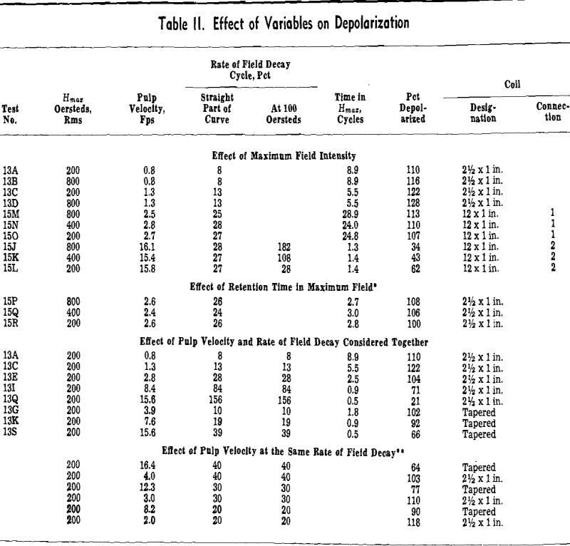
Some preliminary tests were made while experimental techniques were being developed, on the assumption (from Hartig’s work) that the most important factor in depolarizing was the rate of decay of the field in the pulp. These tests indicated that although the rate of field decay was important, the velocity of flow had a significant effect over and above that attributable to the rate of field decay.
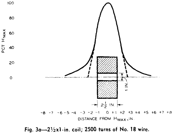
By the use of more than one coil, it was possible to hold all the variables constant except the one under consideration. For instance, the rate of decay in the 12×1-in. coil with connection 1 was approximately the same as that for the 2½x1-in. coil. As the former has a long plateau at the maximum field strength, whereas the latter reaches the peak field only in the coil center, this gave a convenient method for holding all variables constant except retention time in Hmax.
It will be noted that for the coils with a single set of windings (2½x1-in. coil, tapered coil, and 12×1-in. coil, connection 1) the curve of field strength vs distance is a smooth curve of regular shape, whereas for the more complicated connection (12×1-in. coil, connection 2) the rate of field decay changes for different parts of the coil. This introduces the difficulty of evaluating the rate of decay for this type of winding.
Analysis of Data
Effect of Maximum Field Intensity: For this factor the tests within each group (except the 15 J, K, L group) are similar in all respects except Hmax. It will be noted that for the first three groups, Hmax has little effect on depolarizing, with perhaps a slight advantage in favor of high field strengths. The tests of the 15 J, K, L, however, show a significant advantage in favor of low field strengths. These tests were made with the 12×1-in. coil, with the No. 2 connection (irregular field shape). If the rate of field decay here is calculated by the usual method the rates of decay are the same for all three tests.
Discharge Through Orifice and Free Fall Through Coil: The preceding data indicated that streamline flow favors good depolarizing and that if streamline flow prevails (at NRe less than 4000 to 6000) relatively high velocities through the coil can be tolerated. To apply these conditions to pulp flows that might be encountered in a commercial plant, it would be necessary to use a large number of small tubes, with perhaps several tubes passing through a single coil. This would be an awkward arrangement at best and would require a complex installation.
Depolarizing of Cobber Concentrate Before Grinding: In making the design layout for the Pilotac plant, it became evident that the simplest design for closing the ball mill circuit with a rake classifier would be to install the depolarizing coils on the ball mill feed (rougher magnetic separator concentrate), rather than on the ball mill discharge (classifier feed). This proposal was considered seriously, as it would also obviate passing the circulating load through the depolarizing coils and thus require a smaller depolarizing installation. It was also postulated that grinding in the ball mill would improve depolarizing.

