Deep Well turbine pumps receive constantly increasing application to the problem of mining water and other fluids from great depths. Many installations of medium settings are presently operating successfully and it is felt that much greater depths are immediately within reach. Settings and lifts in excess of 2000 feet are not at all out of reason with present knowledge, experience, and materials; however, conditions of individual applications will govern in each case and dictate methods and possibilities to the designer.
Although the deep well turbine pump has been produced in the vertical turbine pump industry for many years, the connotation of the word “deep” still remains questionable. Among the manufacturers of this type of machinery, answers to the question implying the practical-limitation of setting for a deep well pump will vary to an extreme.
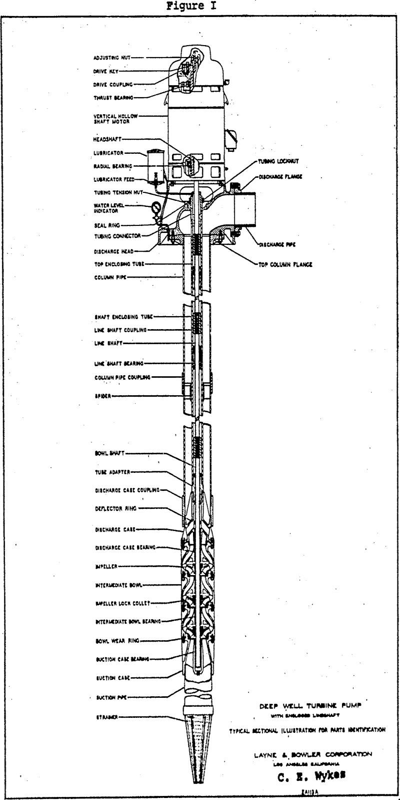
In general, the most dependable design has been found in the oil-lubricated or tube-enclosed lineshaft pump. As illustrated in Figure I, the pumping unit proper or bowl assembly is suspended at the required depth on the column pipe.
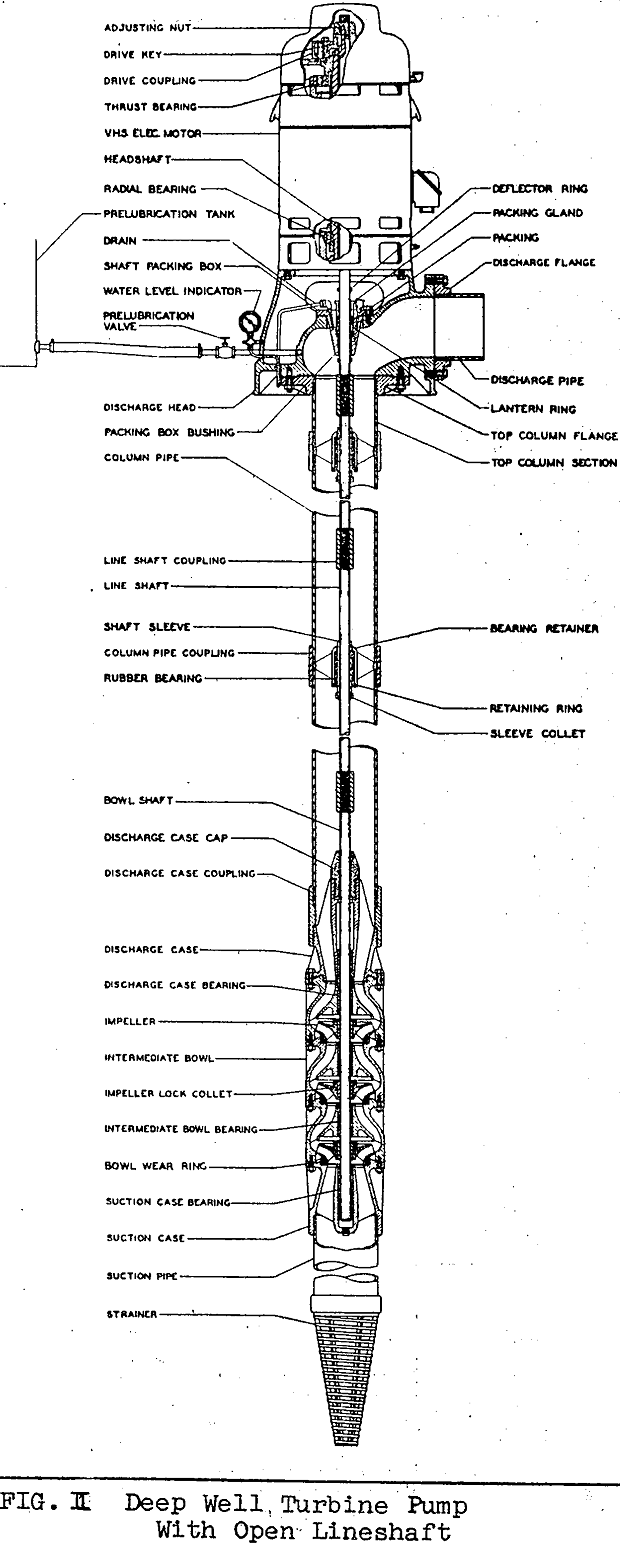
Another version of lineshaft units which appears only rarely in the deeper applications is the open-lineshaft design. This arrangement is similar to the enclosed shaft construction in principle, but the shaft cover pipe is omitted so that the shafting revolves in and is lubricated by the pumped fluid. As shown in Figure II, bearings are mounted in the eduction pipe. Experience upon which this writing is based precludes a recommendation of this design in settings beyond 500 feet, and preferably not over 400 feet in many cases.
Although the foregoing has covered well Installations almost exclusively, deep applications are also to be found in other areas, such as mine shafts. Pumps are used extensively in mining operations, of course for de-watering, leaching, and myriad other purposes.
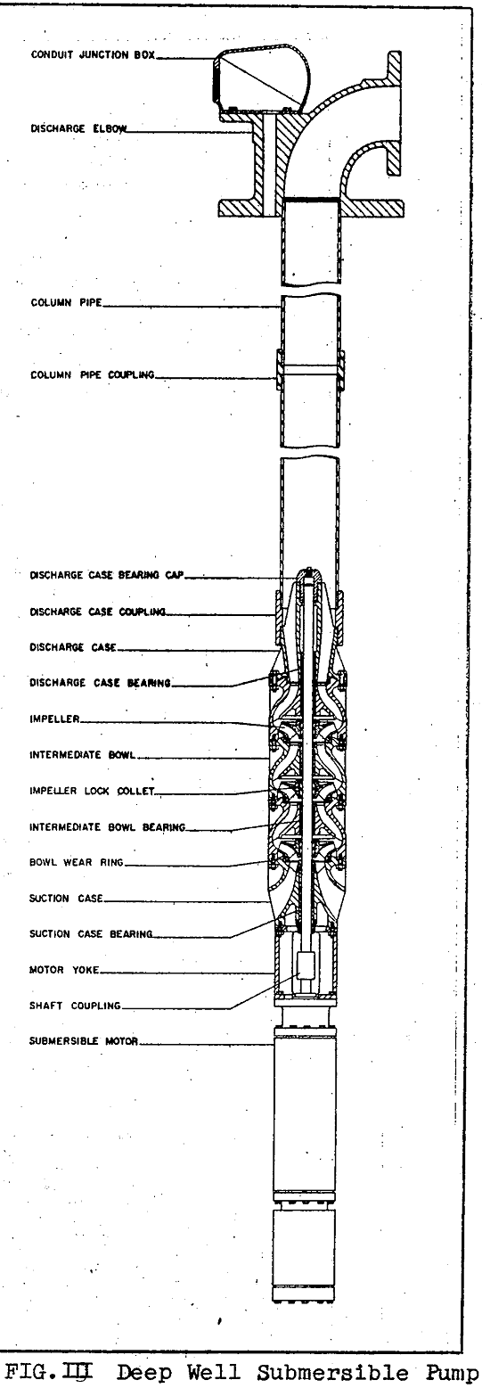
To this point, all description has revolved about the use of surface or, at least, “dry” motors and drivers. Where electric power is available, consideration of the submersible pump is also a factor. Here, the motor is immersed in the fluid, usually attached at the lower end of the pump below the bowl assembly. For very deep settings, particularly below 1500 feet, the submersible cannot be disregarded from an economic standpoint and at times will represent the only physical solution known to us at this particular time. Exceptionally deep operation at many thousands of feet has been attained with special small diameter oil well submersible pumping units, but such equipment will be considered beyond the scope of this paper.
General problems requiring consideration here may or may not stem solely from extreme depth of setting; they may be merely the obstacles usually encountered with turbine pumps; perhaps aggravated or magnified by the setting and pressure. Stresses, of course are ever-present considerations in almost any engineering problem. With high lifts, internal pressure within the bowl assembly may be enormous, although easily contained by sufficient metal strength and thickness.
During operation, however, most reactions are the result of combined loadings and thus far from simple. Shafting, for instance is placed under tension both from its own weight and from the hydraulic downthrust opposing the fluid lift.
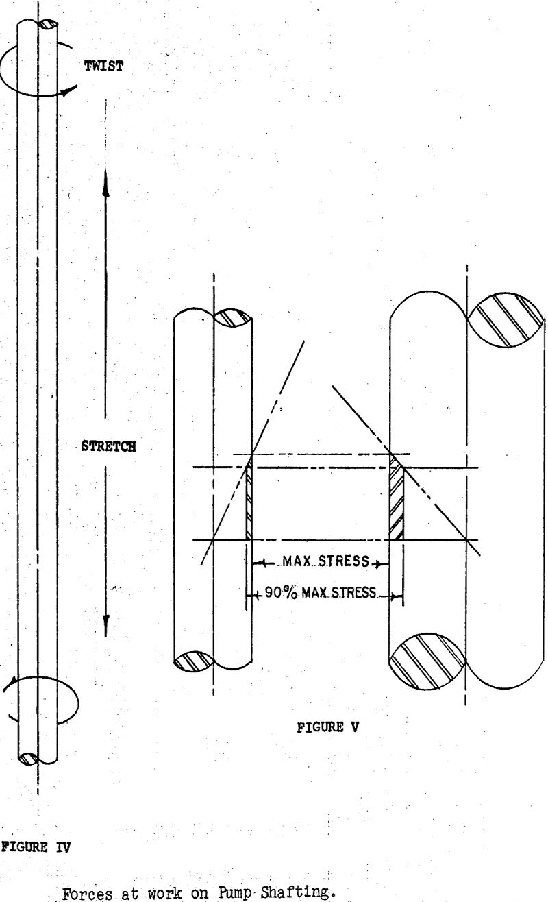
Since a long steel string of shafting of relatively small cross section area acts like a rubber band in some respects, deflections increase greatly in importance with depth of setting. Shaft will stretch of its own weight, of course; it will also stretch farther as the hydraulic downthrust load is applied during operation. When the pump is stopped and the downthrust is lessened by the amount of the hydraulic or liveload, the shaft returns to its length before start-up. This results in a yo-yo effect, and the magnitude of motion may be expressed:
e = 12LFh/EA
where e = elongation inches
L = shaft length feet
E = modulus of elasticity
Fh = hydraulic downthrust pounds
A = shaft cross section area square inches
In analyzing the behavior of pump shafting, angular deflection cannot be completely ignored, either. Since torque is applied in opposite directions on either end, the shaft will twist. The phenomena may be described quantitatively as:

where A = angular deflection degrees
D = shaft diameter inches
l = shaft length inches
t = torque inch pounds
Es = torsional modulus of elasticity-
P = horsepower
N = revolutions per minute
The effect of such deflection may be considerable. That it can shorten bar length appreciably is shown by analysis of Poisson’s Ratio. It is obvious, too, that the continual elastic working – the stretch and release, the twist and return will predispose toward metal fatigue.
Pipe elongation can even assist in providing for impeller endplay room in the bowls, since it will allow the bowls to displace in the same direction as the shaft. This, of course, assumes the timing of the deflections to be identical.
A source of deformation much more difficult to handle lies in the pumping temperature of the fluid. Deep strata often produce water from 100° F and up, with the resultant thermal expansion in all parts. Consider, for instance, the case of a pump installed in a mineshaft: it is possible that the outside of the pump column may be in a cool environment of some 70° F when starting up; the pumpage could well be in ‘excess of 150° F. In such an application, differential displacement between pipe, shaft and tube will never coincide.
Installation and operation of extremely deep turbines usually devolve upon the user. In putting such a unit down a hole, handling equipment becomes of prime importance. For gripping the pipe, slips or some similar device exerting fairly equal pressure around the circumference, are strongly recommended. Any elevators or grips which tend to “egg” the pipe are unsuitable and dangerous. Lifting equipment obviously must be able to handle the full weight of the pump and the actions must be smooth and easy, as shocks or bumps in starting or stopping a lift may result in the loss of the pump down the hole.
For submersible equipment, installation is somewhat simplified since it is necessary only to make up pipe joints going in. The power cable must be put down with the pipe, however, and this will require care in splicing and in attachment for protection and support. Impellers in this type of unit are adjusted for position in the factory or, at the latest, at the surface just before starting in the well.
