Table of Contents
The quarry is located in the western part of the Piedmont Plateau. Geologically, this province is described by Watson as an area of highly metamorphosed sedimentary and igneous rocks of Paleozoic and pre-Paleozoic age. The Piedmont region of South Carolina has extensive areas of granite and gneiss that are suitable for aggregate. The gneisses have similar chemical and mineral compositions to the granites and are therefore designated as granite gneisses. Commercially, both types are called granite, and in this report the more common term is used rather than the more technically correct one of gneiss.
The rock in the Liberty quarry is described as a contorted, biotite granite-gneiss of medium to dark gray color and medium grain size. Composition of the rock is chiefly microcline and albite feldspars, quartz, biotite mica, and small quantities of muscovite mica. Accessory minerals found in the rock are titanite, zircon, apatite, chlorite, epidote, garnet, monazite, and pyrite. The light-colored feldspar and quartz alternate with bands of dark-colored biotite, which generally are thinner and less continuous.
Two samples, selected by the Bureau for estimating the mineral constituents by binocular microscope, show the following results.

Sample 1, from the east quarry face, had a highly contorted, banded structure. Sample 2, from the north quarry face, had a parallel and closer spaced, dark, banded structure.
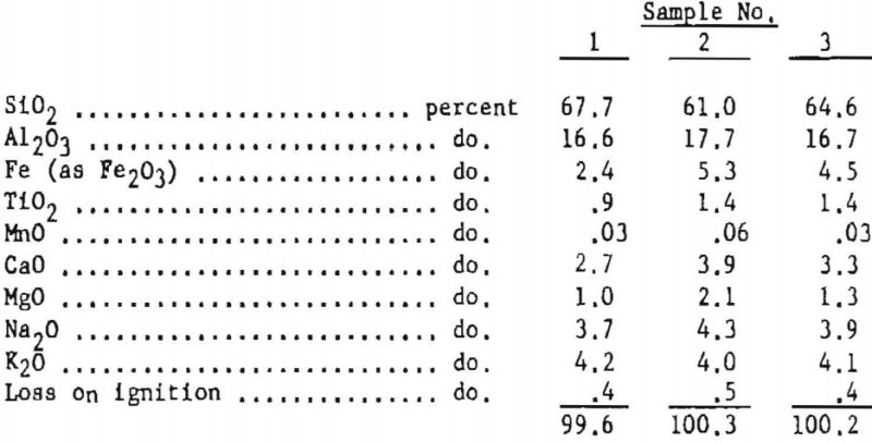
The same two samples, plus sample 3 which is the minus-1/16-inch fraction from conveyor C-13, gave the following chemical analyses:
Structurally, the local occurrence is a dome-shape, intrusive mass. Joints are widely spaced, the most prominent directions being a nearly east-west vertical joint and a N. 30° E. joint dipping steeply southeast. Most of the joints arc tightly closed, but the zone along the northern face where the rock surface is at the lowest elevation has open joints which cause difficulty in drilling and blasting. Horizontal sheeting is not pronounced and tends to parallel the surface doming.
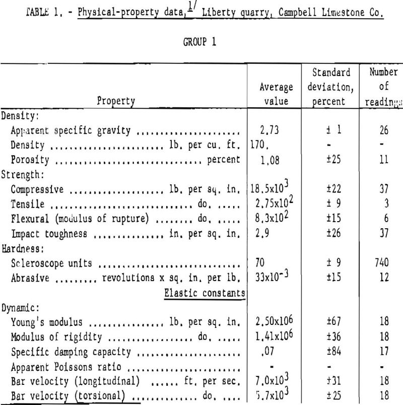
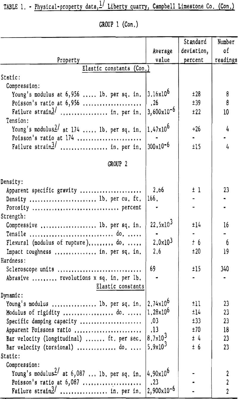
The South Carolina Department of Highways lists the atone from this quarry as having a specific gravity of 2.69 and an abrasive loss of 48 to 52 percent, using the Los Angeles testing method. Table 1 gives additional physical-property determinations.
Exploration and Estimation of Reserves
Observation of exposed granite outcrops and quarried areas supplied all the data needed for quarry development during the first 60 years of operation. On the basis of geologic continuity of the formation, reserves of rock suitable for market requirements are virtually unlimited. The problem is to determine the area most economically favorable for future development. Factors to be considered are: Overburden to be removed; roads, powerlines, buildings, and other obstacles to be relocated; ownership of property; drainage and water table; and vertical and horizontal distances rock must be transported to the processing plant.
Additional reserves to the south and west are not available because of railroad and plant installations. The best choice for lateral expansion is apparently to the north. Accordingly, a drilling program was begun in September 1955 to determine the depth of unconsolidated material and weathered rock to be removed in this area before quarrying. Southeastern Diamond Drilling Co. of Asheville, N. C. was employed to explore the prospective area with a Sprague and Henwood No. 112 drill, using AX bits to produce a 1-1/8-inch core.
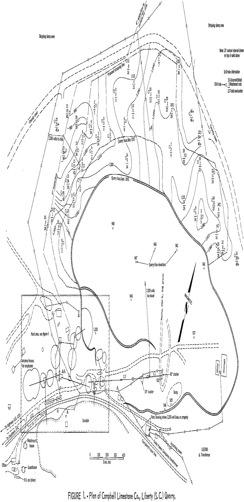
Figure 1 shows the location of the 50 drill holes. It was desired to determine the thickness of the unconsolidated material and weathered stone – defined herein as overburden. Usual practice was to core about 4 feet of the solid stone below the overburden. It was assumed that the stone would continue to be acceptable for quarrying for an unlimited depth. The data obtained by drilling is depicted in figure 1, and the surface of the solid rock is indicated by contour lines.
Exploration work delineated an area to be stripped that contained 35 feet or less of overburden and did not go beyond the county road to the north. As shown on the map (fig. 1) approximately 21.5 acres is to be stripped of overburden ranging from 0 to 35 feet and averaging about 12 feet in thickness – an estimated total of 410,000 cubic yards of waste material. Rock developed down to the present quarry floor (elevation 950 feet) is computed as 5,500,000 tons – a ratio of 13.4 tons of ore developed per yard of overburden removed. The height of the solid stone face varies about 105 feet, ranging from 30 to 135 feet. The surface of the stone slopes as much as 13-½° in a few places, thus creating a problem in operating excavating and drilling equipment.
At the current annual production rate of about 1,000,000 tons, the added reserve is 5-½ years. Plans are to open a lower level 50 to 60 feet below the present quarry floor for additional reserves. Existing roadways, stockpile areas, and buildings occupy about one-third of the present quarry floor and are excluded from calculation of reserves. The remaining 25 acres, plus the newly delineated 21-½ acres, would represent 8,400,000 tons if deepened 50 feet or 10,000,000 tons if deepened 60 feet. This reserve will last 8-½ to 10 years and, added to the 5-½-year reserve, gives planned reserves until 1971 or 1973. Further reserves can be added by either lateral or vertical development; undoubtedly the choice will be greatly influenced by future market requirements and technologic changes.
Development and Mining
General
Early quarrying removed the exposed dome of granite by benching into the side of the hill at natural drainage levels. When overburden increased beyond a desirable ratio, the quarry floor was deepened and it was necessary to pump out inflowing
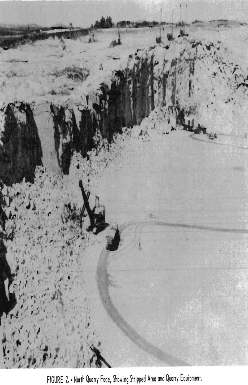
water. The present operating floor is about 80 feet below natural drainage. Total area enclosed by the quarry rim is about 40 acres and is roughly oval shaped, with a length of 2,100 feet and a width of 1,100 feet. The face is being advanced 2,100 feet on the northern and part of the western sides, with face heights ranging from 60 to 125 feet, as shown in figure 2. Present development will enlarge the quarry on this level to about 60 acres.
A sinking cut to open up a new operating level 50 to 60 feet below the present floor is planned for the near future. A haulage road from that level to the crusher will be on a 15-percent grade.
All inflowing water in the quarry drains by gravity to a large sump on the south aide of the quarry at an average rate of 35 gallons per minute (g.p.m.). The bottom of the sump is 10 feet below the lowest point on the floor and 20 feet below the present operating area.
A Fairbanks-Morse pump with a 6-inch suction and 4-inch discharge, powered by a 20-hp. electric motor, pumps the water out of the sump to a discharge point 80 feet above the sump level. Normally the pump is operated only brief periods each day and is started and stopped automatically by a float-type switch. A chain hoist is installed above the pump, so that if water inflow is excessive the pump can be raised to prevent damage to the motor. The sump water is used for wetting down roads and muck piles, which nearly consumes the entire inflow for most of the year.
As the water table is about at sump level, the quarry floor and walls are usually dry. While the cut for the new level is being sunk, it is planned to pump the inflowing water to the present sump. An electric, self-priming sump pump will follow closely behind the shovel excavation. The pump is designed with the motor as high as possible so that heavy rains will not cause trouble.
Removal of Overburden
Overburden is removed during development, and the company contracts this work whenever lateral expansion is required. The waste is used to fill in small valleys an average round-trip distance of one-half mile away.
For excavating unconsolidated material, the last contractor used 15-cubic-yard, Allis-Chalmers scrapers. A 5-vertical to 1-horizontal slope was specified as the limit for stripping.
Weathered rock was drilled with a Gardner-Denver Air Trac drill using 2-inch bits. Compressed air was supplied by an Ingersoll-Rand, 300-cubic-foot-per-minute, rotary-type compressor. Low-velocity explosives loosened the rock, and it was loaded into 15-ton, end-dump, Euclid trucks with a 1-½-cubic-yard, 38-B Bucyrus-Erie shovel. A bulldozer was used to keep the waste disposal pile smooth and fairly level.
Primary Drilling and Blasting
Drilling is done with two 29-T and four 27-T Bucyrus-Erie churn drills. Two drills are powered by diesel and four by electric motors. Electric power is brought in at 2,300 volts and reduced to 220 volts by three transformers mounted on old trucks so that they can be easily moved. The additional work and equipment needed to provide this power supply is more than offset, as the cost of electric power is only about one-half that of diesel fuel and less time is lost in starting and maintenance. The drilling crew consists of 6 drillers, 3 helpers, 1 service truckman and 1 foreman.
Left-lay, ¾-inch-diameter wire rope is used to support the 20-foot by 5-inch- diameter drill stem. The high-carbon steel bits are 6-5/8 inches in diameter and 5 feet long. Average drilling speed, including delays, is 2-¼ feet per hour. Bits are resharpened after 16 to 20 feet of drilling by a shop in a nearby city and have a life of about 1,000 feet.
An investigation is being made of the advisability of changing to a faster, compressed-air drill that may be more efficient than the churn drill. Test holes have been drilled to assist in the comparison, but results are not yet available.
A normal blast consists of one row of holes spaced 27 feet apart, which have an average burden of 18 feet and are drilled 5 feet below the desired floor elevation. Blasting is done about 18 times per year, and the holes are loaded and shot by the drilling crew under the supervision of an Atlas Powder Co. representative. Before the holes are loaded, they are cleaned with an improvised bailer mounted on an old truck. The bailer is dropped down the hole by gravity and hoisted up by a power takeoff on the truck.
Normally the lower part of the hole is loaded with about 400 pounds of 75-percent gelatin dynamite, prepared in 25-pound cartridges 5-½ inches in diameter and approximately 24 inches long. Then 60-percent ammonia dynamite in sticks of similar size is loaded in all except for the top 14 to 18 feet of the hole, which is filled with minus-1/16-inch sand screenings. The first cartridge has an electric cap for a primer and is lowered into place by a rope with a releasable hook as is the one following. Remaining cartridges are slit and dropped down the hole. Dropping compacts the cartridges so that the 75-percent dynamite is confined to about the lower 25 feet of the hole.
Instantaneous and 25-millisecond-delay electric caps arc used in alternate holes. Primacord is also placed halfway down each shot hole as an additional means of detonating the charge if testing reveals a faulty electric circut. After the area has been properly cleared of equipment and personnel, a warning is sounded on a siren, final electrical connections are made, and the shot is fired by closing a switch located in the plant area that completes the electric circuit from the 220- volt side of the drill transformers.
An average of 3.5 tons of rock is broken per pound of explosive. Fragmentation is only fair, probably because the joints are widely spaced. Many large pieces appear to come from the stemmed part of the blast. Drilling and shooting about four 2-inch wagon-drill holes, 15 feet deep and spaced around each large hole, at the same time as the large blast has been tried but has not been adopted as a standard practice. Substituting a cheaper, fertilizer-type blasting agent for part of the 60- percent dynamite has been tried, and indications are that the substitute will be satisfactory.
Explosives are stored in two 30- by 30-foot buildings of suitable construction, located away from the quarry in a valley. The buildings hold about 150,000 pounds of explosives, which are trucked to the blasting sites as required.
Direct operating costs for primary drilling and blasting in 1955 were as follows :
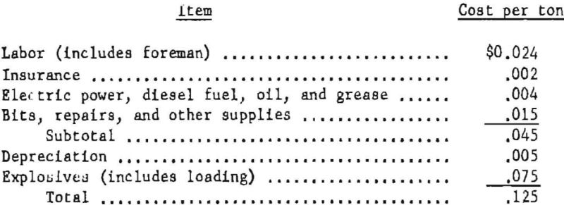
The total for 1956 was about 7 percent higher, or $0.134.
Secondary Breakage
It la estimated that 30 percent of the rock broken by primary blasting is too large to be handled by the quarry equipment and needs secondary drilling and blasting.
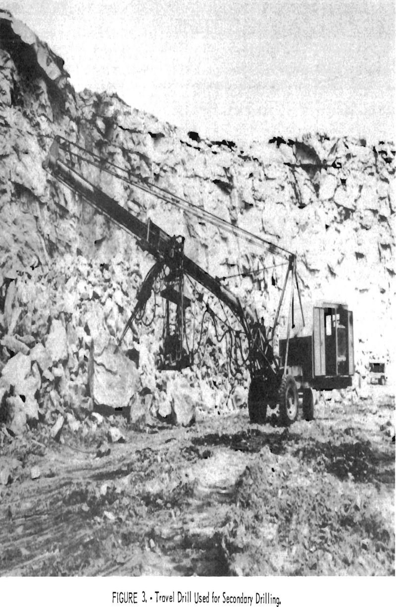
An efficient machine called the travel drill (fig. 3), operated by two men, does about three-fourths of the necessary drilling. This machine has its own compressor, is self-propelled, and is controlled entirely from the operator’s platform, which can be moved to any point along the 40-foot boom that projects over the muck pile. A 1-¼-inch drill bit is used, which has a penetration rate of 1-½ foot per minute, but about one-third of the time is consumed in positioning the drill. The bit is resharpened every 70 feet and has a total life of about 700 feet.
Three jackhammer operators drill the rest of the holes, as many are in places inaccessible to the travel drill. Compressed air is supplied by an Ingersoll-Rand, 300-cublc-foot, rotary-type compressor.
Each day 250 to 300 holes are drilled, and 2 men load them with 30-percent, high-density, ammonia dynamite. Each hole is detonated by an electric blasting cap, and the entire group is usually detonated at the end of the shift. The shot is fired by a du Pont CD-45, type-6412, battery-operated blasting machine from a movable all steel shelter 800 to 1,000 feet from the blasting area.
The cost of secondary breakage is about 56 percent of the cost of primary breakage, or 36 percent of the total drilling and blasting coat. A breakdown of direct operating costs during 1955 follows;
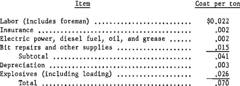
The total for 1956 is about 7 percent higher, or $0.075.
Quarry Loading and Transportation
An electric-powered 100-B Bucyrus-Erie shovel with a 4-cubic-yard dipper and a diesel-powered 1201 Lima shovel with a 3-½-cubic-yard dipper are used to load the broken rock. An operator and an oiler are assigned to each shovel. The power for the electric shovel is 2,300 volts, delivered by a 4-wire (1 for ground) rubber- covered cable. When the shovel is moved, men handle the cable with wooden-handled tongs.
The rock is hauled by truck and trailer units; 6 Easton, twin-body, side-dump trailer units rated at 15 tons are pulled by 2 D933-67E General Motors diesel tractors and 4 LJK Mack diesel tractors. Five units are in use, and the sixth is kept as a spare.
Two units are loaded by the smaller shovel and three by the larger shovel. The shovel swing is kept under 180° by proper positioning of the trucks. An attempt is made to keep one shovel in good digging rock to maintain a uniform production rate. The first truck in the morning is loaded lightly so that production will begin as soon as possible. The truck beds are too small to be in proper balance with the shovel size, as only about 1-½ to 2 dippersfull are needed to fill each side of the twin bodies. A program of modifying the trailers into single-bed units is under way. The new side-dump bodies will have a capacity of 22 tons and will be dumped by an electric motor and hoist; 3 units will be assigned to the 4-cubic-yard-shovel and 2 to the 3-½-cubic-yard-shovel.
Length of haul from the face to the crusher ranges from 800 to 1,300 feet, and the roadway is about level except for a 200-foot, 5-percent-grade ramp at the crusher.
An HD-10, Allis-Chalmers bulldozer is used to push spillage onto the muck pile. Roads are graded with an Allis-Chalmers grader, and a water truck is used to wet down roads and muck piles for dust control. Two operators are assigned to this equipment, but they are used also for miscellaneous pitwork as the water-truck duties do not require their full time. A foreman coordinates all pit activities.
Processing
General
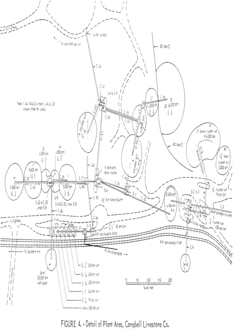
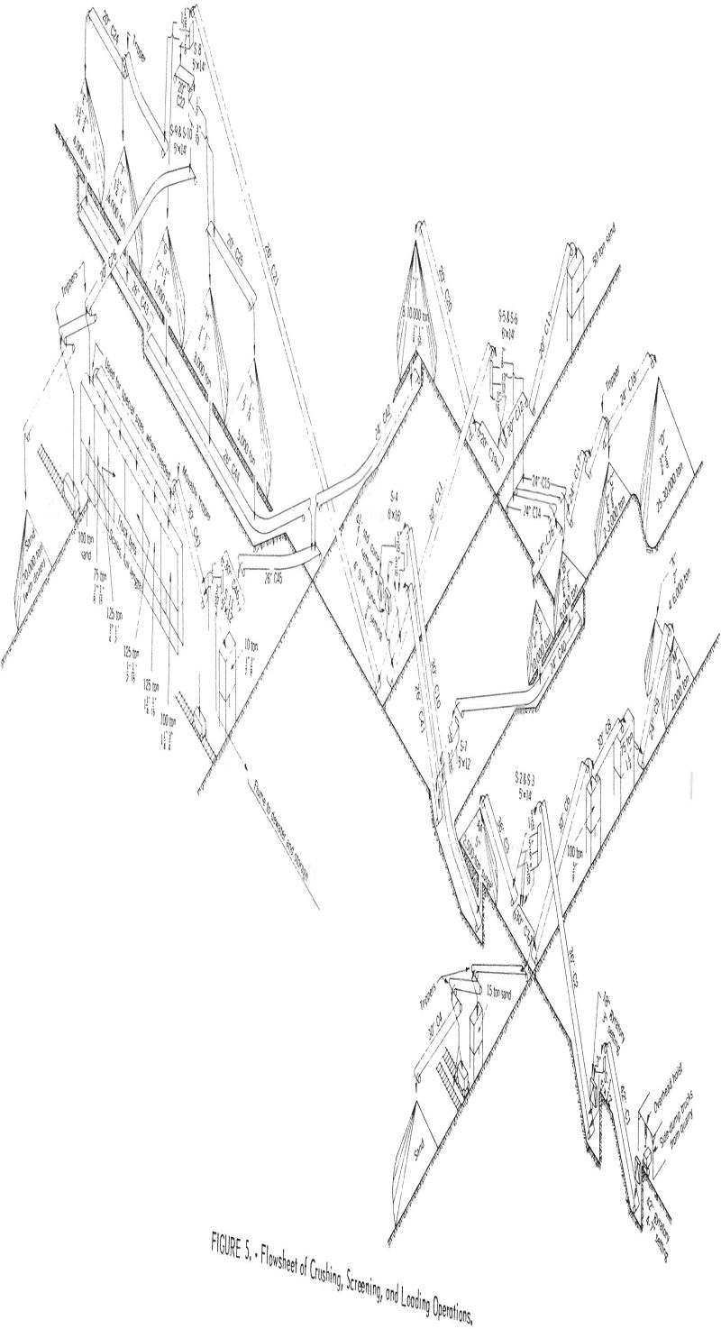
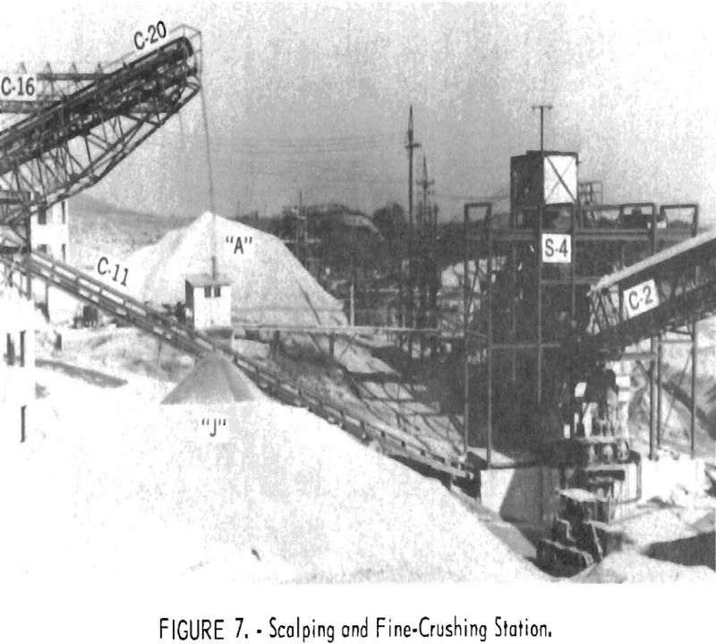
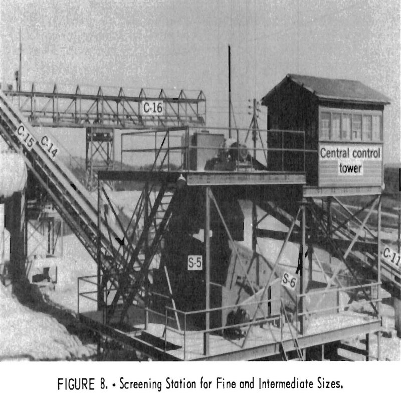
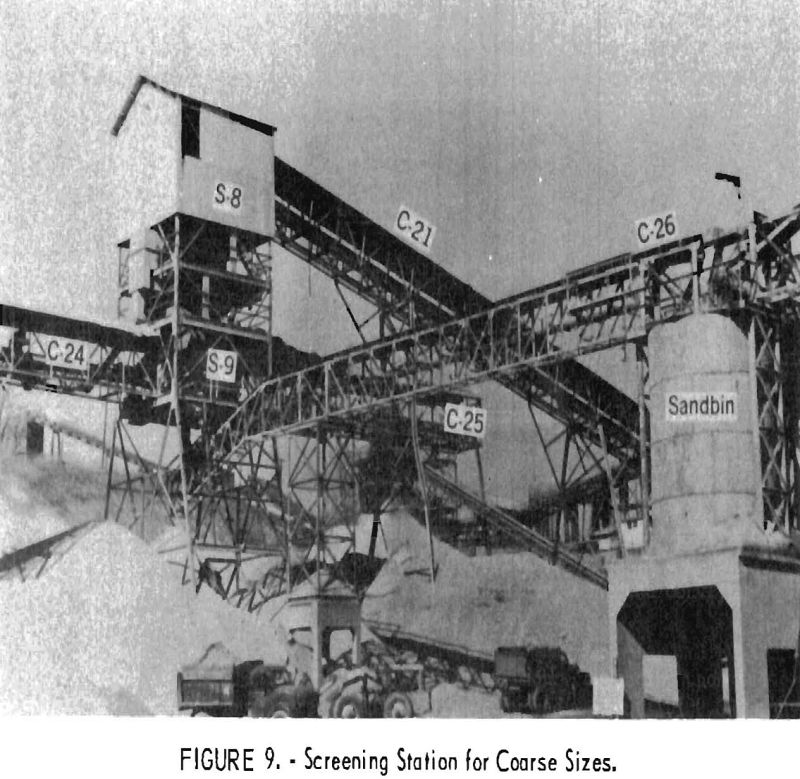
Processing includes crushing, sizing, storing, washing, blending, and loading the stone in preparation for market requirements. Two gyratory crushers and two cone crushers are used for size reduction. Eleven screens sort the stone into proper sizes for storage in 14 open-storage piles and 11 bins. The stone is moved to equipment, storage pile, or loading point by conveyor belt or chute. Figures 4 and 5 show the physical layout of the plant and the flow of material. Figures 6, 7, 8, and 9 show the crushing and screening stations.
The plant is modern in design with concrete foundations and either steel or concrete superstructure. Extensive additions and improvements were completed in 1956, including a central control tower permitting operation by one man of all equipment for producing atone beyond surge pile A-A and operating the conveyor below stockpiles A, B, E, F, G, H, I, and J.
Rated capacity of the plant is 500 to 600 tons per hour, depending upon the size of the quarried stone and degree of processing required. About 1,100,000 tons of stone is fed to the primary crusher per year. An estimated 81 percent is sold as

crusher-run material, washed stone, and stone-sand. The remaining 19 percent accumulates as sand in excess of the present market demand. More of this minus-1/8-inch sand has been sold in recent years, but the ratio of excess has not changed much because the increased demand for the smaller sizes of crushed stone has resulted in larger output of the minus-1/8-inch sand. Moreover, part of the trouble is inherent in the mineralogic makeup of the rock, the high percentage of biotite mica probably accounting for the high losses that develop in processing the larger sizes. At present, approximately 35 percent of the processed stone ends up as minus-1/8-inch material. Of this quantity, it is estimated that 15 percent is sold as sand, 30 percent is sold as crusher-run material, and 55 percent is stockpiled for future use.
The several processing operations are interwoven, but the following groupings are useful in describing flow of materials: (1) Primary crushing; (2) secondary crushing, screening, and storage; and (3) blending and loading.
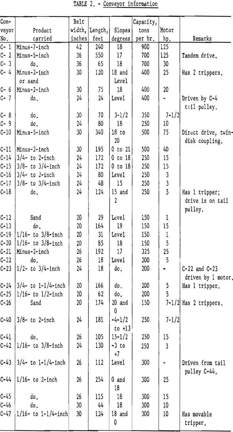
Conveyors are used in all three operations. For convenience, table 2 summarizes the specifications of the 33 conveyors used; in the text the conveyors are referred to by their assigned numbers. The 26-inch conveyors were converted from 24 inches to increase plant capacity.
Since 1954 all conveyors added to the plant have been driven by a direct-drive unit. They are more economical to operate and need virtually no maintenance. The chain and V-belt drives need to be replaced about once a year.
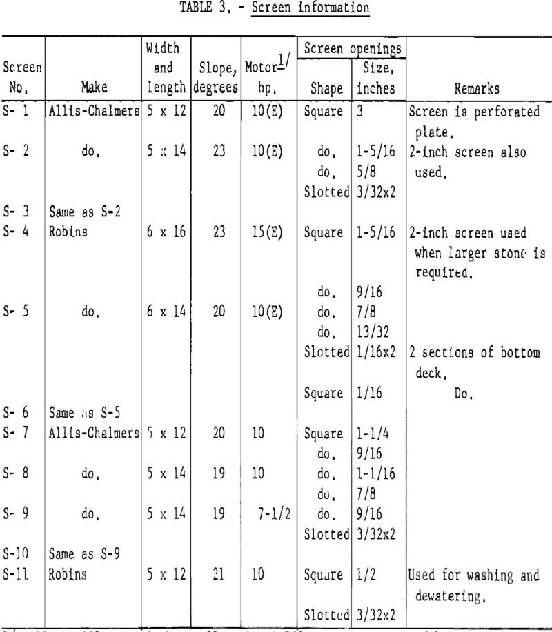
For convenience, screens likewise are grouped together in table 3 and referred to by designated numbers in the text.
Primary Crushing
Primary crushing is done with a 42-inch and an 18-inch Allis-Chalmers gyratory crusher. The large crusher is driven with a 2,300-volt, 3-phase, 885-r. p. m., 250-hp. slip-ring electric motor having a 17.0-inch pitch-diameter motor sheave and 19 D-240 belts to transmit the power to the crusher. The drive for the smaller crusher is similar except that the motor is 150 hp. and only 10 belts are used.
The twin side-dump trucks from the quarry are dumped into the 42-inch crusher by an air-cylinder, hook, and chain arrangement. When single trailer beds replace the present twin beds, an electric-hoist dumping mechanism operated automatically by a pushbutton will be used. The 42-inch crusher is fed opposite the high side of the discharge chute, and an electric overhead hoist actuates a large hook to assist in feeding large rocks to the crusher. About six times per shift a rock too large to be crushed is fed into the crusher. When this happens, the oversize rock is drilled and broken with explosive without removing it from the crusher.
Discharge settings range from 4 to 7 inches because of wear on the mantles and concaves. All quarried rock goes through the crusher, is transported by conveyor C-1, and is scalped by screen S-1, giving a plus-3-inch oversize for the feed to the 18-inch primary crusher. This crusher has the discharge opening set at 2-½ to 3 inches and has part of the feed opening blocked off so as to give a center feed when it is not operating choke feed. Discharge from the crusher and bypass from the scalping screen fall on conveyor C-2 for further processing.
Three men are assigned to the 42-inch crusher and 1 man to the 18-inch crusher a total of 4 men for primary crushing.
Secondary Crushing, Screening, and Storage
Conveyor C-2 delivers stone from the 18-inch primary crusher to the crusher-run station. First, the material is sized by screens S-2 and S-3, which produce a plus-1- ¼-inch, a 1-¼- to 5/8-inch, a 5/8- to 3/32-inch, and a minus-3/32-inch spilt; then, by proper choice of chutes, the various fractions are recombined for the desired product.
When 1-¼-inch crusher-run stone is wanted, the smallest 3 fractions are combined and transported by conveyors C-7, C-6, and C-8 to a 75-ton, square, steel-truck loading bin. A chute from this bin feeds onto radial-stacker conveyor C-9, which provides a storage pile (M) of 2,000 tons capacity. The plus-¼-inch fraction in delivered by chute to C-3 for transport to a 2,500-ton surge pile A-A. Similarly, 2- inch crusher-run stone is made by replacing the 1-¼-inch screen with a 2-inch screen. The radial stacker C-9 is moved to a new position to provide storage for 4,000 to 6,000 tons, designated as pile X.
Production of 5/8-inch crusher-run stone is similar, except that the plus-5/8-inch sizes go to the surge pile, and a chute at the end of C-6 diverts the flow to a 100-ton, round, steel-truck loading bin. A chute below the screens can divert the flow to loading trucks for haulage to an open storage pile.
When neither crusher-run size is needed, the plus-3/32-inch sizes go to the surge pile, and the minus-3/32-inch sand falls on C-7 and then C-4. Two trippers permit the sand to go to a 20-ton, round, steel-truck loading bin, to railroad cars, or to an open-storage sandpile.
A tunnel under the 2,500-ton minus-5-inch-size surge pile A-A permits feeding by conveyor C-10 to the scalping and secondary crushing station as the first step in producing closely sized stone. Scalping screen S-4 splits the feed into plus-1-¼-inch, 1-¼- to ½-inch and minus-½-inch sizes.
The plus-1-¼-inch stone is feed for a 4-¼-foot standard Nordberg cone crusher having a feed opening of about 7 inches and a discharge opening of 1-inch on the close side. The 1-¼- to ½-inch size is feed for a 4-foot, short-head, Nordberg cone crusher, which is set for a discharge of ½ inch on the close side. The 1-¼- to ½-inch size can bypass the crusher and be chuted to C-21. Each crusher is driven by a 2,300-volt, 3-phase, 885-r. p. m., 150-hp., squirrel-cage electric motor having a motor sheave of 19.9-inch pitch diameter and a crusher sheave of 36.3-inch pitch diameter and using 12 D-210 V-belts to transmit the power. Outside oil tanks are used with inside oil pumps, and an alarm bell rings if the oil supply fails. An overhead 10-ton hoist is installed for repair work, and enough clearance is provided under the crusher to permit a man to work for cleanup, greasing, and repairs.
Both crusher discharges are fed to C-11 for sizing in the fine- and intermediate-size screening section. By means of gates and by removing certain screens, the feed to the 4-foot short-head crusher can be bypassed to C-11 or can go to the 4-¼- foot standard crusher, permitting operation at a reduced speed when the 4-foot short-head crusher is being repaired. Moreover, the 1-¼-inch top-deck screen is replaced with a 2-inch screen if larger stone is required. The minus-½-inch undersize from S-4 is chuted to C-21.
From the secondary c rushers C-11 carries the intermediate and fine sizes to screens S-5 and S-6. Products made are plus- or minus-2-inch to ¾-inch, ¾- to 3/8-inch, 3/8- to 1/16-inch, and minus-1/16-inch. The plus-¾-inch size is chuted to C-14 then to C-16, where it falls onto a 10,000-ton-capacity storage pile, A. The ¾- to 3/8-inch size is transported by conveyors C-15, C-17, and C-18, which by gates and tripper arrangements can be placed in any of three storage piles having capacities of 6,000 (B), 2,000 to 3,000 (C), and 25,000 to 30,000 tons (D). The 3/8- to 1/16-inch size is placed in an 8,000- to 10,000-ton storage pile (J) by C-19 and C-20. The sand goes to a 50-ton, square, steel-truck loading bin by C-12 and C-13, Sand in excess of sales is hauled by two 2-ton dump trucks to open storage piles, which are leveled with a bulldozer.
The plus- or minus-2- to ¾-inch and the ¾- to 3/8-inch stone from piles A and B can be drawn from below by gates in a tunnel under the piles and placed on C-40 for reprocessing. This stone is fed onto screen S-7 through 1-¼- and 9/16- inch screens. If a top size of 1-¼-inch is desired, the plus-1-¼-inch stone goes to the secondary crushers on C-10, and the minus-1-¼-inch sizes to the screening tower on C-41 and C-21. If additional crushing is required, the plus-½-inch stone can be sent to the crushers on C-10 and the minus-½-inch size goes to the screening tower.
The 2- to 1-¼-inch stone off the top deck of S-8 drops by gravity to a 1,000- ton storage pile, G. The 1-¼- to ¾-inch stone is fed onto C-24, which by means of a tripper places this size into two 4,000-ton stockpiles, E and F. The ¾-inch undersize is split and chuted to C-22 and C-23 to feed screens S-9 and S-10, which produce sizes of ¾- to ½-inch, ½- to 1/16-inch, and minus-1/16-inch. A chute places the ¾- to ½-inch material in a 3,000-ton stockpile (H), and C-25 carries the ½- to 1/16-inch size to a 5,000-ton stockpile (I). Sand is transported by C-26, which has two trippers to place the sand in a 100-ton, round, steel-truck loading bin, into railroad cars, or In a 20,000-ton sand-storage area.
Employees assigned to secondary crushing, screening, and storage are, 1 operator, 1 oiler, and 1 truckdriver at the crusher-run station during the day shift and 1 central control operator, 1 oiler, and 1 tunnelman each on the day shift and night shift for operations beyond surge pile A-A – a total of 9 employees.
Blending and Loading
Sand is loaded simply by opening gates below the 3 storage bins provided for truck haulage or by the 2 conveyor-belt trippers for railroad cars. Similarly, crusher-run material is loaded into trucks from the truck storage bins and into rail-road cars by C-7 and C-4. Open-storage-pile loading into trucks from crusher-run piles M and X or from the 3/8- to ¾-inch atone pile D is done with a 5/8-cubic-yard or a ¾-cubic-yard shovel. Material from C is recovered by bulldozing over to pile B.
Storage piles E, F, G, H, I, and J have drawoff gates and conveyors in tunnels under the piles. By means of conveyors C-42 through C-46, each size or any blend of sizes can be brought to a washing and scalping station for final preparation before being loaded. Stone is discharged at a rate of 250 to 300 tons per hour from C-46 into a feedbox along with low-pressure water at a rate of 200 g. p. m., which provides a scrubbing action. Additional washing and dewatering, as well as scalping off the remaining minus-1/6-inch sand is done by screen S-11, which is equipped with a water spray of 200 g. p. m, near the feed end.
The washed, graded stone is loaded into railroad cars by chutes. Reversing a gate drops the stone to C-47, which has a movable tripper that distributes the various sizes to truck storage bins. Four bins have capacities of 125 tons each for storing ¾- to ½-, ½- to 1/16 , 1-¼- to 1/16-, and 1-¼- to ¾-inch sizes; the fifth bin of 75 tons capacity is used for the 3/8- to 1/16-inch size. A sixth bin of 100 tons capacity, normally used for sand, can be made available for special stone sizes when needed. Also a 10-ton, square, steel-truck loading bin filled by chute from S-11 is provided for the ½- to 3/8-inch stone.
Scales the full length of the concrete truck loading bins facilitate rapid handling of truck sales. The company has a contract with a trucking firm to haul all truck stone except that for some contractors and individuals who haul their own. A water hose is available for truckers to wet down their loads to control dust.
One man in the main office is responsible for taking orders for sales, obtaining railroad cars, billing out shipments, dispatching truck orders, and collecting money for cash sales. A telephone service between the office and the scale house facilitates the work. Rail shipments are weighed on scales that record automatically on weight slips. These slips are picked up once a day, the proper car numbers added, and bills prepared.
Blending and loading operations are on two shifts. Personnel on the day shift are, 1 foreman, 1 scaleman, 1 tunnelman, 1 plant operator, 1 truck-bin operator, and 1 shovel operator and road-maintenance man – a total of 6. The night shift comprises 1 foreman, 1 tunnelman, and 2 men for railroad-car loading – a total of 4.
Maintenance and Repairs
The cost of maintenance and repair is an important item in producing crushed stone. The high percentage of silica in the stone makes it quite abrasive, and the handling of large sizes before secondary crushing also makes for high impact damage. All work is done in shops on the property or at the machine site. Workers assigned to this section are 5 welders, 3 mechanics, 1 electrician, 3 helpers, and 2 foremen – a total of 14. Operators assigned to a machine also assist in emergency repairs.
A 40- by 60-foot welding shop is equipped with electric and acetylene welding machines, a power band-steel cutting saw, two punch presses for holes up to 1-inch in diameter, an automatic acetylene cutting burner, and smaller tools. Hoppers, chutes, skirt boards, and smaller steel structures are made in the shop, and general repair work is done there. The new trailer units already described are being built in this shop.
A 30- by 30-foot truck shop is equipped with necessary tools and a service jeep for maintaining all trucks, graders, loaders, pickups, jeeps, shovels, and travel drills and for sharpening the carbide drill bits used for secondary drilling.
A 20- by 40-foot machine shop is equipped with a lathe, steel-cutting power saw, planer, keyway cutting tool, blacksmith forge, drill press, and other small tools. Pouring bearings, threading bolts, and adapting or repairing machine parts are done in this shop.
The quarry and crushing equipment requires more major maintenance and repair work than other processing equipment. Rebuilding shovel teeth every 24 operating hours with manganese-steel welding bars and rods takes one welder nearly full time. A program of lining all trailer-truck beds with manganese-steel plate is under way. One unit was modified in this manner 2 years ago and proved very satisfactory.
The eccentric on the 42-inch primary crusher must be replaced every year. A winch service truck is used to install the eccentric, and the repair takes about 24 hours. Concaves need to be replaced every 2 years and mantles every year; these replacements take 72 and 20 hours, respectively. A spare shaft-and-mantle assembly is provided so installation can be made as a unit; life of the worn mantle can be increased indefinitely by using 1-¼-inch manganol bars welded in place with electric welding rod.
A similar procedure is followed in replacing the eccentric on the 18-inch primary crusher. Approximate service is 1 year for eccentrics, 2 years for concaves, and 1 year for mantles; estimated repair times are 6, 20, and 10 hours, respectively. A spare mantle-and-shaft assembly is kept on hand.
Certain practices of design have contributed to less maintenance work. When possible, chutes and hoppers are constructed, so that rock will build up to form its own wearing surface, thus saving wear on the steel. Moreover, the welding of old high-carbon drill steels in chutes transverse to the direction of flow has provided a good wearing surface.
Feed distributing boxes, fastened onto the feed end of all screens receive the impact of falling stone from chutes. Conveyor drive pulleys have been lagged with grooved belts that reduce slippage, make a more efficient drive, and reduce wear on the belt itself. Interlocking units electrically to prevent continuation of feed to a stopped machine reduces breakage and wear. Overfeeding on the secondary crusher is controlled by a plate installed in the feed chute that lifts and rings a warning bell if the stone builds up beyond a safe point.
Auxiliary Operations
A 60- by 100-foot concrete-block building is used to store supplies, spare parts, and equipment, Trucks pass down a central runway, and an overhead hoist facilitates loading and unloading. A 20- by 30-foot building used to store replacement screens.
Compressed air is required for the truck-dumping hoist, aeration of sand bins to promote flow of sand, and miscellaneous plant uses. Two Ingersoll-Rand, piston-type compressors are housed in a 30- by 30-foot building. The air is piped to a receiver tank and to the various points of use.
Water for washing the stone, wetting down the loads, and miscellaneous plant needs is supplied from a pond formed by a small dam across a stream about one-half mile north of the quarry. A 3-inch Gould centrifugal pump, driven by a 100-hp. motor, and a 6- by 15-inch Fairbanks-Morse centrifugal pump, driven by a 200-hp. motor, deliver the water to the plant area in a 6-inch waterline. A shortage of water in dry periods hampers operations, and it is planned to dredge a larger reservoir area behind the dam to correct this shortage.
The company has converted a railroad car, originally designed for use of railroad officials. Into a diner and lounge. A cook is employed, and the noon meal is furnished to key employees. A guesthouse maintained by the company also is available. Employees classified as auxiliary are 1 warehouseman, 1 pumpman, 1 cook, and 2 watchmen – a total of 5.
Supervision, Engineering, and Office Personnel
All operations at the Liberty quarry are supervised by a plant manager and a quarry superintendent. Four men are assigned to purchasing, accounting, payroll, sales, and other duties.
An engineer is stationed at the Liberty plant but is responsible for all three company plants. The department, the president of the company, and the plant managers determine changes, additions, or new equipment to be installed. Detailed specifications are prepared, checked, and presented for price quotations.
Fabrication, erection, and installation of equipment is the responsibility of the engineering department. Small changes are usually handled under the direction of the plant superintendent with the engineer acting in an advisory capacity.
Labor Distribution
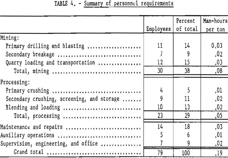
Table 4 summarizes personnel requirements at the Liberty quarry. Figures for man-hours per ton are based upon an average workweek of 44 to 48 hours and a yearly production of 1,000,000 tons of quarried rock. In terms of salable stone the figures for man-hours per ton would be proportionately higher.
The pay period is weekly, and checks are prepared and distributed on the Friday following the end of the pay period.
A group plan is in effect for life insurance, hospitalization, and surgical benefits. The company pays about half the cost and the employee the remainder.
Power Distribution
Approximately 200,000 to 260,000 kw.-hr. of electricity, 1,300 gallons of gasoline, and 3,000 to 4,000 gallons of diesel fuel are consumed a month, or 2.76 kw.-hr. of electricity and 0.06 gallon of fuel per ton of quarried rock.
All electric power is purchased from Duke Power Co. and is supplied to the Liberty plant as 2,300-volt, 3-phase, 60-cycle current. The 2,300-volt current is carried to all motors over 50 hp. and to transformers by overhead wires. Voltage is reduced to 220 volts for motors less than 50 hp, and to 110 volts) for plant lighting.
A breakdown of power requirements in horsepower-hours per ton of quarried stone for the quarrying and processing operations follows:

Related: Best Drill Press for Metal
