Design and Construction
The mill design and construction was accomplished through the combined efforts of Equipment Company in Colorado, Equipment Company (Peru) S. A., and Sindicato Minero Pacococha S. A. The design objective was a highly efficient mill at a minimum expense, and with plans to allow for a systematic expansion program to increase the mill capacity from approximately 125 tons per day to approximately 200 tons per day with minimum interruption of the plant operation and with a minimum of additional equipment.
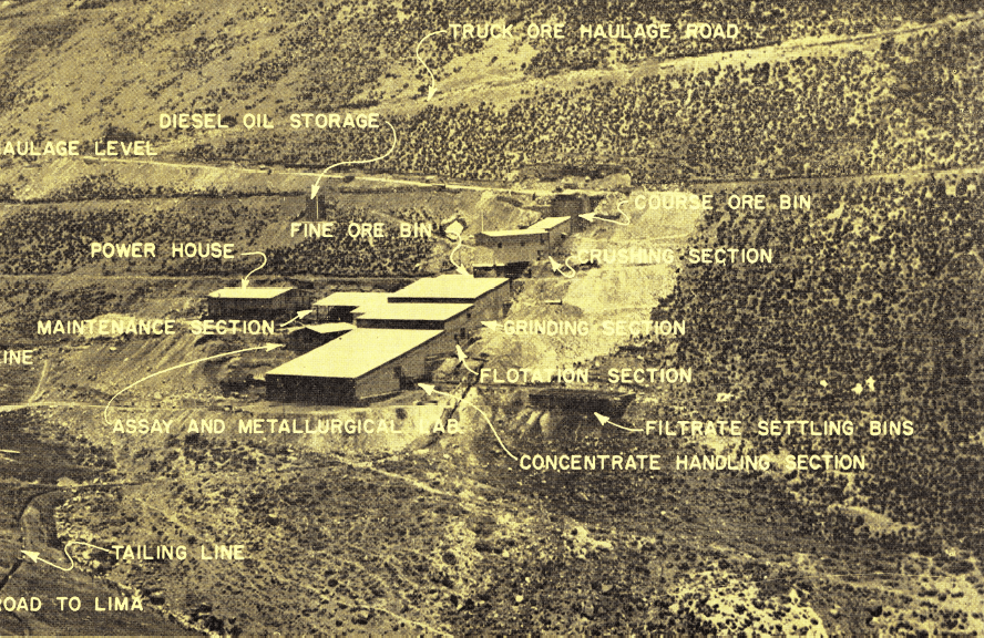
The mill was located so a favorable downhill ore haulage track grade of .05′ per 100′ could be obtained, together with a gravity flow of water from the lake.
A mill site having an average slope of approximately 30° was selected in order to provide a completely gravity flow throughout the plant with a minimum of building expenses.
When designing a flotation plant for a planned future expansion, many factors have to be considered other than installing additional machinery. These factors include such things as additional ore haulage, coarse ore capacity, water supply, power and power distribution, piping, launder, etc.
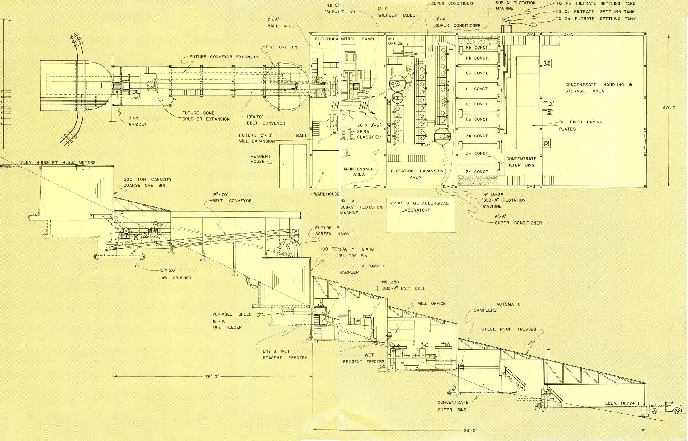
For example, the coarse ore bin has a live load capacity of approximately 200 tons and a dead load capacity of 300 tons. Provision was made to change the dead load storage area into a live load area by installing an apron ore feeder under the coarse ore bin. Also, the type of coarse ore bin designed permits the addition of bins to be installed to the sides with minimum expense.
The present crushing section is a conventional single-stage crushing system; however, the basic design provides for the addition of a screen, belt conveyor and secondary crusher with minimum stoppage of the mill and without any major modification in any of the basic structures. Note that both crushers are located so that they can be supervised by one operator. When the second crusher and screen are installed the mill will have a conventional two-stage closed circuit crushing section which will increase the overall mill capacity 20 to 40 percent. This expansion is already under way.
In the grinding circuit an additional ball mill is provided for on the other side of the classifier. With this installation and the conversion of the present 5′ x 8′ ball mill to a rod mill, a two-stage rod mill-ball mill grinding circuit is provided to give an expected increase in tonnage of around 50 to 75 percent, with lower power and maintenance cost per ton of ore treated. This installation can be made without affecting mill production during the construction period and without changing any conveyors or other major equipment in the grinding circuit.
Room has also been provided for additional flotation cells, thickeners and filters, and other miscellaneous equipment for handling the additional tonnage.
There are other features such as the location of the mill office near the master electrical controls, from which all major equipment is visible; providing overhead cranes above the flotation cells; balancing the lights between incandescent and fluorescent lights for improved visibility; access roads to all major sections or operating levels of the plant particularly to the grinding area; adequate drainage on all floors for easy cleaning; a large area for concentrate handling, etc.
One other point of interest is that whenever possible Peruvian design and building techniques were used. Most of the vertical retaining walls and some of the lighter building foundations were built from stone. The Peruvian Indian dating back to the Incan era has been noted for his outstanding stone work. All major foundations and supporting walls, however, were constructed of concrete.
Mining
The mine is located about one mile from the concentrator and the two are connected by a 2.5 mile long automobile road. An electric railroad is presently being installed.
The mine has three upper production levels called the “40”, “100” and “145” levels with several other levels being in the development stages.
A lower level, called “275” level, is in the development stage and will be used as a haulage level for the mine, and it is anticipated that in the near future this level will also be productive. Two raises are being driven to connect the working levels to the haulage level.
The mining method used is shrinkage stopes.
The “Purisima” vein strikes in a North-South direction with ore shoots 50 to 100 meters long, separated by barren sections of similar dimensions. There are approximately 10,000 feet of tunnels and 5,000 feet of raises. The upper workings of the mine are at an elevation of 15,500 feet and the haulage cross cut, level “275”, is at an elevation of 14,900 feet.
There are 175 men engaged in underground development and production. Hand tramming is used extensively underground using Type U-27 Ore Cars.
MILLING OPERATIONS
Development of the Flowsheet
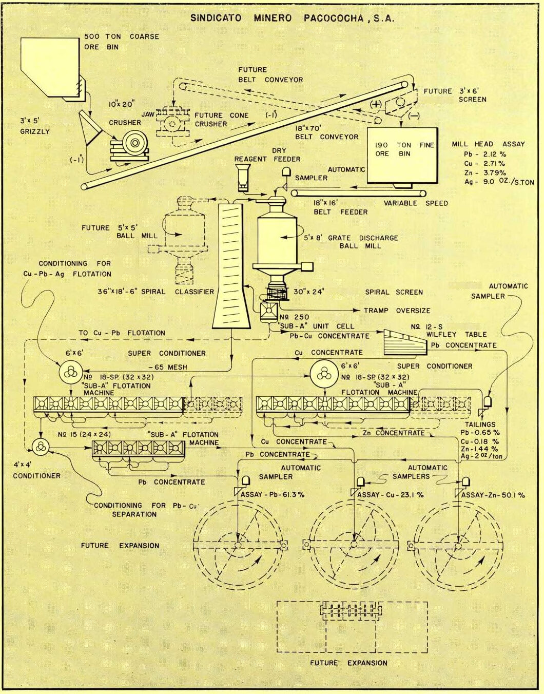
The ore was tested by the Ore Testing Division in Colorado, during the early part of 1959. The results of this test work together with actual operating results from the Banco Minero Mill were the basis for a selective flotation flowsheet for producing lead-silver, copper-silver, and zinc concentrates. The mill consists of a single stage crushing, single stage closed circuit grinding, flotation of a copper concentrate in the unit cell, flotation of copper-lead-silver concentrate, and flotation of a zinc concentrate. The bulk copper-lead-silver concentrate is then subjected to reflotation using cyanide to depress the copper and float the lead. The concentrates are de-watered in “Cochas” or filter bins.
Ore Haulage
The present ore haulage is by trucks via a 2.5 mile long road from the upper workings of the mine. A one-
mile long electric railroad is being installed. The mine cars inside the mine and cars for the haulage railroad are Type U-27 Ore Cars.
Mill Water
The mill water flows by gravity from Lake Pacococha via a 6″ diameter by 2,000′ long pipeline. No mill water storage tank is used as the lake produces the required head.
Power
The power is supplied by a 600 rpm supercharged MAN-AEG diesel and generator set. This unit has a sea level rating of 360 kilowatts and a rating at 15,000 feet of 240 kilowatts. There are two 60 kw Caterpillar diesel units used as standby. Room is left in the power building for an additional large diesel electric unit. The electrical system is 3-phase, 60 cycle, 220/440 volt.
TABLE OF CONNECTED HORSEPOWER
1. 10″ x 20″ Crusher…………………………………………………….30.0 HP
2. 18″ Conveyor…………………………………………………………….5.0 HP
3. 18″ Feeder…………………………………………………………………1.5 HP
4. 5′ x 8′ Ball Mill………………………………………………………100.0 HP
5. 36″ Classifier…………………………………………………………….5.0 HP
6. No. 250 Unit Cell……………………………………………………….7.5 HP
7. 6′ x 6′ Conditioner……………………………………………………..5.0 HP
8. 10-cell No. 18-S “Sub-A” Flotation Machine……………….37.5 HP
9. 6′ x 6′ Conditioner……………………………………………………..5.0 HP
10. 10-cell No. 18-S “Sub-A” Flotation Machine………………37.5 HP
11. 4′ x 4′ Conditioner…………………………………………………….2.0 HP
12. 6-cell No. 15 “Sub-A” Flotation Machine……………………15.0 HP
13. No. 12-S Table…………………………………………………………..1.5 HP
14. Miscellaneous equipment and lights…………………………30.0 HP
Coarse Ore Bin
The coarse ore bin has a live capacity of 200 tons and a dead capacity of 300 tons. This ore bin is of an unusual design and is a combination of reinforced concrete and steel. This type of construction requires no internal bracing members. A grizzly with 6″ opening, constructed of railroad rails, is provided over the coarse ore bin.
At present the discharge from this bin is by a vertical gate at the end of the bin; however, a tunnel and a slot in the bottom of the coarse ore bin have been provided so that the dead load section of the bin can be converted to a live load section by installing two or three feed chutes and a conveyor or apron feeder in the tunnel.
Crushing
The ore passes over a 3′ x 5′ wedge-bar type grizzly having 1″ openings ahead of a 10″ x 20″ Type “H” Jaw Crusher set at 1″ opening. The crushed ore, along with the minus fraction from the grizzly, drops onto an 18″ Conveyor and is transported directly to the fine ore bin.
Ample room is provided in the crushing section to install a secondary gyratory crusher, a screen and an additional belt conveyor. This installation, which is currently being made, will provide a two-stage closed circuit crushing section.
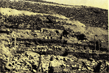
The Pacococha Mill site with benches in process of excavation. The mill site has a 30° slope which provides full gravity flow through the mill.
The present crushing capacity is approximately 125 tons per 8-hour day. With the addition of the secondary crusher it is anticipated that capacity will be 25 tons per hour producing an average 3/8″ to ½” particle size.
Fine Ore Bin
The 18′ x 18′ Welded Steel Fine Ore Bin has a live capacity of approximately 190 tons.
Feeder
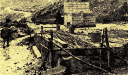
Native stone foundations were used wherever practical. All bearing walls and machine foundations were of reinforced concrete.
A Variable Speed Ore Feeder 18″ x 16′ accurately delivers fine ore from the ore bin to a combination drum scoop feeder on the Ball Mill.
Grinding Section
A 5′ x 8′ Grate Discharge Ball Mill is operating in closed circuit with a 36″ x 19′-3″ spiral classifier and a No. 250 Unit Flotation Cell.
The grinding circuit produces a minus 65-mesh flotation feed at a rate of 125 tons per day.
The 5′ x 8′ Ball Mill was selected so that is could easily be converted to a 5′ x 8′ Rod Mill and an additional 5′ x 5′ Ball Mill could be put into the circuit, thus eventually giving an open circuit rod mill grinding in conjunction with a ball mill classifier circuit.
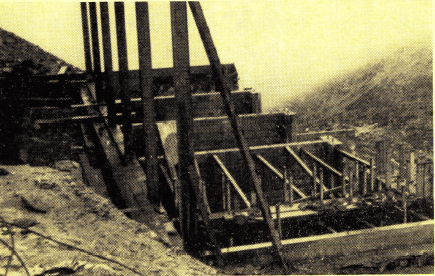
“Cochas” or filter bins being constructed. Side walls are of reinforced concrete to withstand the stresses of the wet concentrates. Concentrates, direct from the flotation machines, drain to 5 to 15% moisture depending on length of storage. After further drying concentrates are bagged for shipment.
Flotation
Flotation can be broken down into four different flotation processes: Copper flotation in the unit cell, bulk lead-silver-copper flotation, zinc flotation, and lead-copper separation.
The use of a Unit Cell in the ball mill- classifier circuit was indicated as an important step to recover a high percentage of copper with low lead content, since the copper proved to be a much faster floating mineral than the lead mineral.
A No. 12-S Wilfley Table is used on the unit cell concentrate to separate the copper from the lead when the lead content runs too high. The unit cell concentrate can also be treated in the copper-lead flotation separation circuit.
The classifier overflow is conditioned in a 6′ x 6′ Super-Conditioner and then the lead-copper- silver bulk flotation is conducted in a 10-cell No. 18 Special “Sub-A” Flotation Machine, using 3 cells for roughing, 5 cells for scavenging, 1 cell for cleaning and 1 cell for recleaning. This complete recycling process is done without the use of any pumps and once again shows the flexibility and simplicity of the “Sub-A” Flotation Machine.
The bulk flotation tailing is treated in another Super-Conditioner where copper sulfate and other reagents are added for the flotation of zinc. A 10-cell No. 18 Special “Sub-A” Flotation Machine is used for zinc flotation and is divided into 6 cells for roughing, 2 cells for cleaning, and 2 cells for recleaning, the final tailing is then sampled and sent to the tailing dam by gravity.
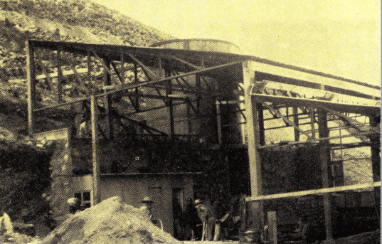
Mill nearing completion. This view shows the grinding floor with the fine ore bin seen in the upper center. Mill is of combination wood pillars and steel trusses with roofing and siding of corrugated steel.
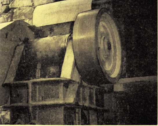
The 10″ x 20′ Forced Feed Jaw Crusher being installed has a capacity of 125 tons per 8-hour day. This crusher, plus an additional secondary crusher, will supply tonnage for the expanded mill capacity.
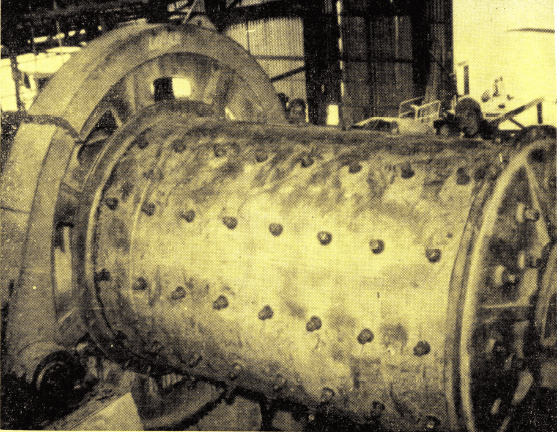
The 5′ x 8″ Ball Mill has a grate discharge but will be converted into a rod mill at a later date. A new 5′ x 5′ ball mill will be installed to handle increased tonnage as the mill capacity is increased.
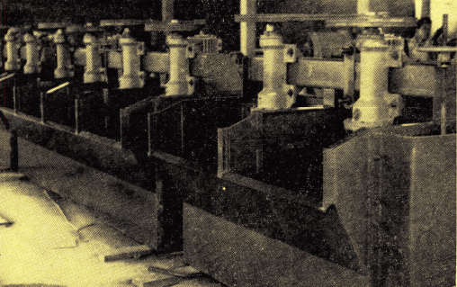
A 10-cell No. 1 8-S “Sub-A” Flotation Machine at the DECOPE factory in Lima prior to shipment to the mill.
The lead-copper-silver concentrate is conditioned in a 4′ x 4′ Super-Conditioner with cyanide for depression of copper. The flotation of the lead from the copper is conducted in a 6-cell No. 15 “Sub-A” Flotation Machine, having 3 stages of separation. The silver is equally distributed with the lead and the copper concentrate.
It should be noted here the particular arrangement of the flotation section. The small lead-copper separation flotation machine is located opposite the bulk lead-copper flotation machine while the zinc flotation machine is located in another area. This provides closer operational control over the complete copper-lead-silver circuit.
The complete flotation section is designed for future expansion and provides for additional cells on both the bulk lead-copper flotation machine and the zinc flota-
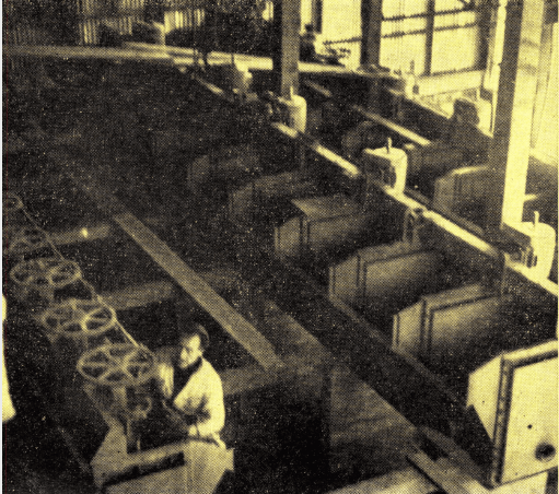
Installation of the No. 15 and No. 1 8-S “Sub-A” Flotation Machines at Pacococha. Note the access area beneath the flotation floor.
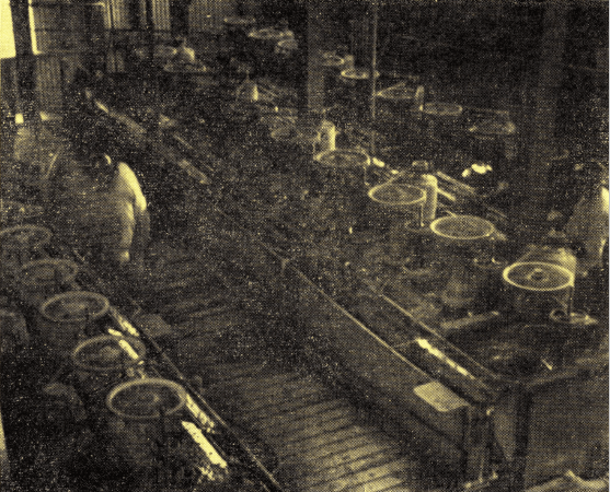
“Sub-A” Flotation Cells at Pacococha Mill. The center bank of ten No. 18-S cells is the Pb-Cu-Ag bulk flotation section. The 6-cell No. 15 machine at the left is the Pb-Cu separation circuit and the 10-cell No. 18-S machine at the upper right is the zinc circuit.
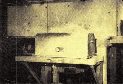
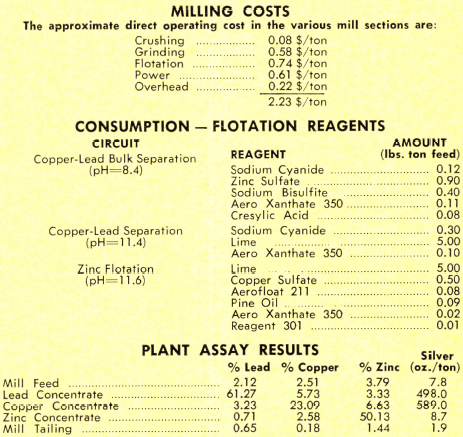
Automatic Sampler on final mill tailings. Sampling is used extensively at the Pacococha mill for operating control. Automatic Samplers are installed on the heads, tails and on each of the three concentrate lines.
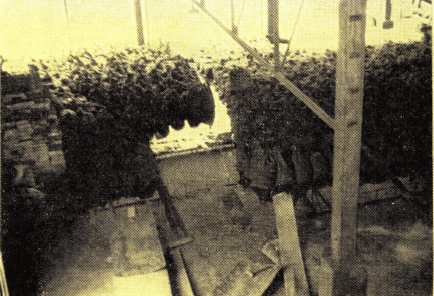
A general view of the concentrate bagging and storage area. Mill commenced operation before this section was completed and this photo shows some of the concentrates produced before all the siding was in place.
tion machine. The conditioners and the lead-copper separation machine are oversize, thus providing additional capacity.
There are no pumps in the mill with the exception of a 2″ x 2″ SRL-C Pump which is used only as a clean-up sump pump and is located on the flotation floor.
Filter Bins
The flotation concentrates are sampled and sent to filter bins for dewatering. Two bins are used for lead, four bins are used for copper, and three bins are used for zinc. These bins give a total capacity of 270 tons of lead concentrate, 320 tons of copper concentrate, and 460 tons of zinc concentrate. The piping and distributing system is arranged so that one bin is being filled while the other is draining.
If required, the concentrates can be further dried by oil fired heating plates. The water discharge from the filter bins is kept separate and distributed to settling tanks where fine copper, lead, and zinc concentrates are recovered in small amounts.
Ultimately a conventional thickening and vacuum filtration system will be installed.
Sampling
Complete sampling of feed, concentrate, and final tailing is provided by Automatic Ore Samplers.
A concentrate distributing system was worked out so that concentrate samples can be taken independent of the filter bin or cocha which is being used. A small metallurgical and assay laboratory is being constructed for mill control and also future testing of ore.
Concentrate Handling
All concentrates are sacked in 150 pound sacks and are trucked to Lima and then shipped to foreign markets.
Acknowledgment
Equipment Company expresses thanks to Sindicato Minero Pacococha, S. A. for permission to report in detail on their Pacococha Mill. Special acknowledgment is due to the General Manager, Sr. Ernesto Baertl, M., who assisted in assembling the data for this article.
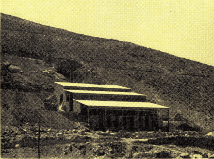
The Pacococha Mill in final stages of construction. All materials for mill construction except for the native stone were transported by truck from Lima some 75 miles away. All construction labor other than the supervisors were local workmen largely inexperienced in construction, but well acclimated to the 15,000 ft. elevation.
