Table of Contents
A 2,000-ton Copper Leaching plant for the treatment of the accumulated copper concentrator tailing was built and put into operation. During the experimental period, the first step was that of laboratory experiments or beaker leaches. The results on this small scale were so satisfactory that a
small operating plant, capable of handling 5 tons of roasted tailing per day, was installed. Again, the results proved satisfactory and an 80- ton plant was built and operated continuously. In this plant, full-sized roasting and leaching units were
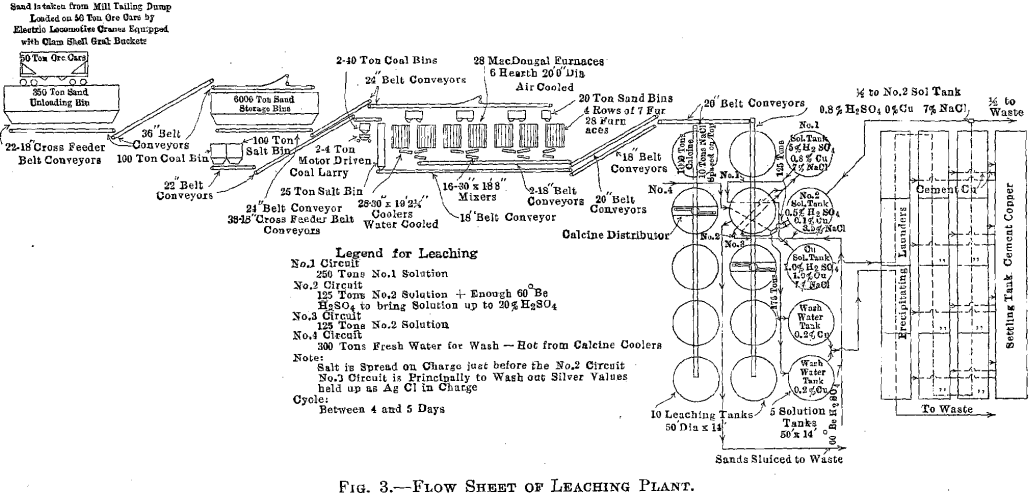
used. The results obtained by the operation of the 80-ton plant proved that the roasting and leaching of deslimed concentrator tailing could be profitably done, so in the early spring of 1914, the construction of a 2,000- ton leaching plant was begun (Figs. 1 and 2). Operation of the plant began and a flow sheet of the plant is shown in Fig. 3.
Leaching Plant Feed
The accumulated tailing in the New Works dump is estimated at about 20,000,000 tons. The dump consists of the concentrator tailing discharge, over a period extending to the present date. According to daily samples taken during that period, the copper content is about 0.64 per cent, and the silver 0.48 oz. per ton. The peak of the dump, or the point where the tailing is discharged, carries about 0.75 per cent, copper, while down toward the toe, and where present excavation is taking place, the copper content is only 0.57 per cent. About 3 lb. per ton of the copper is oxidized, the remainder being sulphide.
The following shows an average screen analysis of the tailing in the dump:
Cumulative Percent

An average analysis of tailing being treated at the present time follows:

The dump is being excavated by a Bay City Industrial Works electric hoist, equipped with a 4-yd. bucket. The hoist loads the tailing into 50-ton ore cars. These are hauled to the leaching plant storage bins in trains of 15 cars each. The hoist is capable of hauling 3,000 tons in 8 hr.
Conveying and Storage Equipment
Unloading Pit
The loaded cars of tailing are spotted by means of a 25-ton electric locomotive operated by the third-rail system. The unloading pit is a steel bin capable of holding 350 tons and is of sufficient length to allow three cars to be unloaded at a time. On top of the pit is a 2-in. grizzly, through which all tailing must pass before going to the storage bins. This grizzly serves to keep out rocks or lumps which would block the feeders, furnaces, etc. Under the steel bin are 22 short-belt feeders, each feeding from its own gate and running at right angles to the length of the bin. These feeders discharge onto a 36-in. belt running lengthwise, which in turn delivers the sand to another 36-in. belt traveling on an 18° angle to the top of the storage bins. The system will handle over 3,000 tons of tailing in 8 hr.
Storage Bins
The storage bins will hold 6,000 tons of sand tailing. This gives between two and three days supply for the leaching plant, in case of railroad troubles or difficulties due to cold weather. The bins are of substantial wood, construction and are inclosed, the walls and roof of the building consisting of wood sheathing covered with corrugated iron. The bins are arranged in a double row and are hopper-bottomed. The tailing is distributed over the bins by means of a 36-in. belt and movable tripper.
Underneath are 36 gates, each with its hopper from which an 18-in. belt feeder delivers to a 24-in. belt running the full length of the building, in the center. By means of other belts, traveling through a tunnel under the railroad tracks, and up an 18° incline, the feed is delivered to the top of the furnace building.
There are also small coal and salt storage bins from which a 22-in. belt system conveys coal and salt to bins in the roaster building, the salt being drawn from there to the leaching building as it is required. All belts run at approximately 400 ft. per minute.
Roasting Equipment
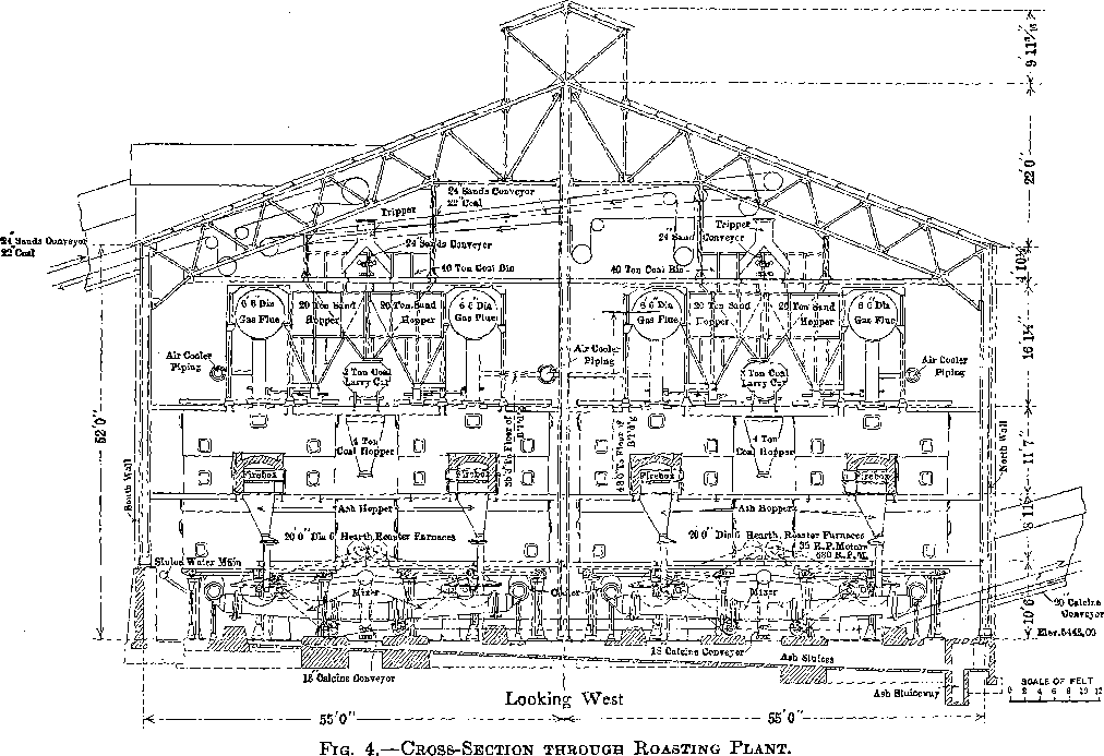
The furnace building is 232 by 110 ft. and is of steel and concrete construction (Fig. 4).
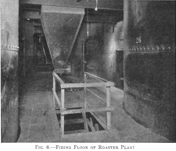
There are 28 McDougall-type, six-hearth furnaces arranged in four rows of seven each. The furnaces are 20 ft. in diameter, each being equipped with two fireboxes, diametrically opposite, the flame entering over a fire bridge directly into the third hearth, the top hearth being designated as the first. The grate dimensions of each firebox are 3 by 4 ft. (Figs. 5 and 6).
Each furnace has a 20-ton feed hopper, to which the tailing is delivered by means of two 24-in. belts each equipped with a movable tripper. The furnaces are fed by 14-in. belt feeders drawing from these hoppers, the amount of feed being controlled by gates which are operated by means of a screw adjustment, the feed dropping through a hole in the top arch, directly onto the top floor (Fig. 7). During the time the feed is on the two upper floors, it is dried and heated; as it drops
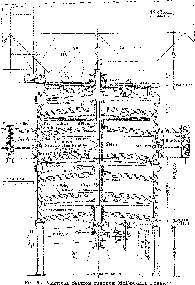
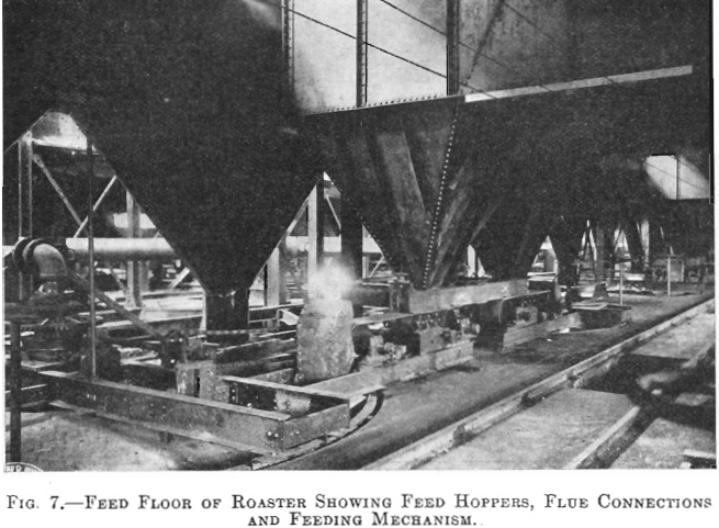
to the third or fired floor, the sulphur ignites. The three lower floors are kept hot by the combustion of the sulphur in the tailing.
Four flues run the length of the building, one over each row of seven furnaces. Each furnace has two opposite connections, from the top hearth to the flue. All four flues lead into a balloon flue with a downtake of 45°. The balloon flue enters the 15 by 200-ft. steel stack with a 45° uptake. The stack is lined with brick. In the bottom of the balloon flue is a 6-in. screw conveyor which delivers the flue dust to the belt- conveyor system which receives the calcine from the furnaces.
The furnaces are air-cooled, the air being furnished by four No. 11 Buffalo blowers each direct-connected to a 50-hp. motor. The air intake is at the top of the furnace shaft and the discharge at the bottom. The hot air does not enter the furnaces, but is delivered to the leaching and solution buildings for heating purposes by a suitable piping system. When it is not needed for this it is discharged into the atmosphere.
Each furnace is equipped with a cylindrical cooler, 30 in. in diameter and 19 ft. long. The cooled calcine enters a mixer or concrete-lined steel cylinder, at the head end of which a very small stream of water is added to settle the dust. The mixer discharges a moist warm calcine to an 18-in. conveyor belt, and by a system of conveyors the calcine is delivered to the leaching building.
The ashes from the fireboxes drop into launders and are sluiced out through the main tailrace.
Leaching Plant Equipment
The leaching building is 293 by 122 ft. and is of steel and wood construction. It contains 10 redwood tanks each 50 ft. in diameter, and 14 ft. deep, lined with 8 lb. lead. The average charge to a tank is about 1,000 tons of calcine.
The tanks are equipped with an ordinary filter bottom, made of 1¼- in. slats resting on 2 by 4-in. pieces. Above this are two layers of heavy cocoa matting and on top of the matting is a grating, made of 1¾ by 3½-in. material, with 6-in. square spaces. The grating fills with calcine 3½-in. deep and serves to keep the force of the sluicing water from tearing the matting. The acid solutions rot the cocoa matting, but if not disturbed, it will hold its shape and be an efficient filtering medium long after it is too much decomposed to handle.
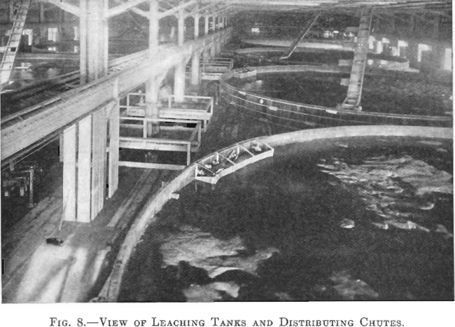
The tanks are in two rows of five each. A 20-in. conveyor belt travels over each row, and, by means of a tripper, the calcine is dumped into a distributor, which spreads it over, the tank (Fig. 8).
Each tank has three lead pipes 4 in. in diameter and one 4-in. iron pipe entering at the top. The lead connections are for strong and dilute acid solutions and the iron pipe is for wash water. Above the level of the leaching tanks an iron storage tank is provided for holding the stock of concentrated acid. Its capacity is about 120 tons of 60° Be. acid. All concentrated acid, used to raise the acid strength of any solution, is added to the solution as it goes on the charge in the leaching tanks.
There are seven 10-in. sluicing gates in the bottom of each leaching tank, one in the center and six spaced equidistant from each other in a circle about half way between the center and the circumference of the tank. These discharge into launders which connect with the main tailings launder.
“Acimet” valves and lead piping are used throughout for handling dilute and concentrated acid solutions.
The floors of both the leaching and solution buildings are of concrete, and are painted with an asphalt-tar mixture for acid proofing. These floors slope to a gutter which connects to a pump sump and in this way any overflow or leakage of solution is saved and returned to the system.
The solution tank building is a leanto off the leaching building and contains five solution-storage tanks. These are 50 ft. in diameter and 14 ft. deep. Solutions drain from the leaching tanks to the storage tanks and are pumped to the top of the leaching tanks, from the solution tanks, by means of vertical shaft, direct-connected, hard-lead, centrifugal pumps.
Precipitating Division
The precipitation of the copper and silver is accomplished with scrap iron. The precipitating launders are of concrete, each about 250 ft. long and having a section of 4 by 8 ft. available for containing iron. Each launder is partitioned off into four sections by concrete walls. Any of the 12 sections may be bypassed for the purpose of cleaning up. In the bottom of the launders is a heavy wood grating, upon which the iron rests, leaving a space about 6 in. under it, for accumulation of any cement copper which may drop off the iron. In the side of each section, at the bottom, are four 6-in. holes, toward which the concrete bottom slopes. These holes discharge into launders which carry the copper to a settling tank. There it is washed and stored and finally excavated with a clamshell bucket, loaded into standard railroad cars and, at present, shipped to the briquetting plant before blast-furnace treatment. An electrically operated Brown hoist, equipped with a lifting magnet, handles the scrap iron and loads the copper.
Details of Operation
Roasting
The tailing is subjected to a simple oxidizing roast, no particular care being taken to obtain a large amount of sulphate. The sulphur content of the feed is about 2.2 per cent, and that of the calcine about 0.6 per cent. One-third of the total sulphur in the calcine is in the form of sulphate. When too hot a roast is attempted in order to decrease the total sulphur content, a certain portion of the copper is rendered insoluble in all ordinary acids, with the exception of hydrofluoric.
A pyrometer is inserted over the fourth floor of every furnace, and by means of these, the firemen are able to keep constant control of the temperature. The best results are obtained by keeping the fourth floor at about 500° C. The hottest hearth in the furnace is the third or fired floor, and averages about 535° C.
The water for the calcine cooler system enters at about 40° C., is discharged at 65° C., and is piped to the solution building, where it is used to heat the circulating solutions. It is then pumped back and used again in the coolers. The calcine after passing through the coolers, and after the addition of 1 per cent, moisture, while going through the mixers, has a temperature of about 45° C. During the conveying from the roasters to the leaching tanks, this temperature is lowered to 40° C.
Leaching
The leaching is done by continuous downward percolation, no circulation or upward percolation being used. The percolation rate will vary from 3 in. per hour with the first solution to as high as 10 in. per hour with the wash water. As nearly as possible, all solutions and wash waters go on the charge at 40° to 50° C.
It requires about one-fourth of the weight of calcine, in weight of solution, to saturate a charge thoroughly.
There are five solution tanks: One for storage of No. 1 solution, one for No. 2 solution, one for copper solution, and two for wash-water.

After a tank is charged with calcine and leveled, 250 tons of No. 1 solution is added as fast as the charge will absorb it. The drain valve is always open, so, as soon as the solution reaches the bottom of the tank, it commences to drain to the copper-solution storage tank as copper solution. From the copper-solution tank there is only one outlet, which is to the precipitation launders. After traveling through the launders, two-thirds of the solution is returned to the No. 2 solution tank and the balance wasted. This waste is necessary to keep impurities such as iron and aluminum sulphates from building up in the system.
When the No. 1 solution has all been added to the leaching tank, the solution is allowed to drain until none shows on top of the calcine, when 1 per cent, of the weight of the charge, of common salt (NaCl), is spread over the calcine. On top of the salt is then added 100 tons of solution from No. 2 solution tank, but with additional strong acid to bring it to 20 per cent. H2SO4. Following the 20 per cent, acid solution, 150 tons of No. 2 solution is added, but without additional strong H2SO4. This scheme gives a zone 4 or 5 ft. in depth of very strong chloridizing solution, traveling down through the charge. There is about 8 per cent, of ferrous and ferric iron in solution, which, with the salt, forms ferric chloride, in itself a very corrosive reagent, even dissolving a considerable amount of unroasted sulphide. This chloridizing action also gives the silver extraction, as without it very little silver is recovered. The 150 tons of No. 2 solution which follows the 20 per cent, acid is for the purpose of washing out silver chloride and dissolved copper which may have been held in the calcine. It carries very little copper or acid, but is fairly high in salt content, and therefore better than a clean water wash. Following the last acid solution, about 300 tons of hot, clean water is added.
The two portions of No. 2 solution, one at 20 per cent, acid, and the other at 0.5 per cent, acid, after percolating through the charge, drain to the No. 1 solution tank.
The wash water, less a quantity sufficient to make up for the discarded solution, drains to the two wash-water tanks. The balance goes to the No. 2 solution tank and adds enough to make up the amount of solution discarded from the precipitating division each day.
Precipitating
The practice here is too old to necessitate much explanation. The main advantages in the practice at this plant over the usual practice are the large launders, which make it possible to put in large and odd-shaped pieces of iron, and the presence of salt in the solutions which prevents the copper from plating on the iron, and makes a soft spongy cement copper which is easily washed off with a hose, leaving the iron clean for more precipitation. It is never necessary to remove the iron for cleaning. The silver is recovered by precipitation on the precipitated copper.
Results
The resulting cement copper carries about 70 per cent, copper. The following data are taken from the reports for the month of October, 1915. This is a representative month, but it is certain that the results will be improved upon, after longer operation.
Sand tailing treated, tons………………………………………………………………..70,401.00
Copper in feed, per cent……………………………………………………………………..0.575
Silver in feed, ounces per ton……………………………………………………………….0.45
Copper in tailing, per cent…………………………………………………………………..0.082
Silver in tailing, ounces per ton……………………………………………………………0.14
Sulphuric acid (60° Be.), pounds per ton of feed…………………………………..64.90
Coal, per cent, of feed………………………………………………………………………….3.30
Salt, per cent, of feed…………………………………………………………………………..1.52
Iron, pounds per pound of copper…………………………………………………………..2.00
The plant during this month made an extraction of about 80 per cent, of the copper and 60 per cent, of the silver. This is less than indicated by assays, of heads and tailings owing to various plant losses of which the largest is dust from the roasting furnaces amounting to about 4.5 per cent, of the copper in the feed.

Discussion
F. N. Flynn, Clifton, Ariz.—I would like to ask Mr. Mathewson what percentage of his leaching liquor is wasted at this time? It has a bearing on the question in connection with the New Cornelia, and I think it is a very important question.
E. P. Mathewson, Anaconda, Mont.—I am not sure what the percentage is now, but we don’t discard the strong liquors. Something like 25 per cent, of the wash water taken out each day is sent over a special set of scrap iron tanks, and the copper recovered there. We had a little trouble at first. We did not proceed to use the sponge iron for the reason that the plant we originally contemplated was abandoned for flotation. Our original idea was to use a leaching process on all the tailings of the mill, but we found it would take a great deal of time to build a plant; and the cost of operating the plant we estimated to be about the same and the recovery the same. It was a question of time with us, and we decided to adopt flotation. That changed our plans. We now have the leaching plant, treating the tailings of the old dump, and the flotation applied to the current tailings. The sponge iron was figured for the large plant. We can get all the scrap iron necessary for the small plant—plenty from the scrap produced in the main plant of the smelter.
The Chairman (H. W. Morse, Los Angeles, Cal.).—I would like to open this meeting for a little while to the general subject of leaching. We ought not to hold back if we have any new schemes for the future. I know that those of us who are tangled up with this leaching work will appreciate any suggestions that will make us work harder and scheme harder to pull through these past difficulties on leaching.
F. S. Schimerka, Clifton, Ariz.—Under the direction of J. W. Bennie, General Manager of the Shannon Copper Co., Clifton, Ariz., it has been my valued privilege to cooperate in the elaboration of a hydrometallurgical process aiming at the recovery of copper in mill tailing resulting from a gravity concentration of a low-grade semi-oxidized sulphide ore occurring in a porphyritic gangue.
The experimental work which has been carried on with a 25-ton plant is completed, and the company is building at present a leaching plant on a larger scale, the first unit consisting of a 150-ton roasting furnace and accessories for leaching the calcine.
I wish to lay before you only the most essential points of our process, the outstanding feature of which is the non-application of acids or any other chemical in the leaching operation proper. After a sulphatizing roast conducted under well-defined conditions in a mechanical roasting furnace of the multiple-deck type, the calcine is treated with water only.
The separation of the copper liquor will be effected by decantation, and the copper, at least for the present, precipitated by scrap iron. The character of the tailing, which is highly basic and remains so even after roasting, prohibits the application of sulphuric acid, which is consumed to the amount of more than 10 lb. for each pound of copper dissolved from the calcine. Our mill tailing, all of which passes through a 1-mm. opening, contains an average of 20 lb. of copper to the ton, 1 per cent., we may say. Fifty-five per cent, and more of the total copper is present in oxidized condition, mainly as malachite and azurite, the balance is chalcocite. Sulphur is present in the amount of 1 per cent., mostly as pyrite. The precious metals are practically absent, and that no attempt at their recovery need be made has materially simplified our working procedure.
The manner in which the roasting of the raw tailing is conducted is, of course, vital to the process, there being no other means employed to convert most of the copper into water-soluble sulphate than the agencies of heat, oxygen and sulphur during the passage of the material through the furnace. A close regulation of the temperature in the roaster by means of pyrometer control is essential. Tests have shown that the re-formation of water-insoluble basic copper sulphate and oxide takes place when the temperature rises closely to 900°F., and we aim at keeping the temperature on the hottest floor between 830 and 860°F. We have encountered no difficulty in accomplishing this. It is, however, necessary to limit the amount of sulphur in the charge to a quantity which in an empirical way has been found to produce the best results, and which excludes the possibility of local overheating, as would take place by the oxidation of a large amount of pyrite. Moreover, any excess sulphur will, by formation of sulphur dioxide, decrease considerably the oxidizing effect of the hot gases striking through the furnace. Our roaster gases contain less than 0.1 per cent, of sulphur dioxide when issuing from the stack. For these two reasons, we aim at keeping the charge as poor in sulphur as we can afford to do without injurious effect upon results. Taking the copper contents in the tailing as a basis, we adjust the sulphur in the charge to 1½ lb. for each pound of copper in the tailing. This necessitates the addition of per cent, of sulphur to the charge in the form of iron pyrite.
For fuel we employ oil burned in an external firebox, which is air-jacketed to prevent loss by radiation. The fire gases which, mixed with the required volume of air admitted through openings in the firebox, at the entrance into the furnace, are kept at 800°F., are sent into the 10- deck roaster on the ninth floor. We do not employ muffles. The fuel consumption in the 25-ton roaster was 5 gal. of oil per ton of tailings treated, frequently less, and we are confident that we can decrease it to 3 or 3½ gal. at the most in the large roaster, on account of heat-saving devices incorporated in its construction. Also, there will be another source of heat provided by the exothermic reactions that take place during the roasting process in the furnace. The additional heat derived from these reactions is quite considerable and has made itself felt to an appreciable degree in the small pilot furnace.
In the new plant, the separation of the copper liquor from the leached calcine will be effected by counter-current decantation in three Dorr thickeners. Directly from the roaster the calcine is discharged into a circular mixing tank where it receives return liquor from one of the thickeners. From the mixing tank the pulp and liquor pass into three Dorr classifiers placed in series to effect a separation between the sand and slime. The slime in the overflow from these classifiers passes successively through the three thickeners, the first of which delivers its clear overflow to the precipitation boxes. As the pulp progresses through the battery of thickeners it is washed by water and waste liquor from the precipitating launders traveling in the opposite direction.
During our test runs with the 25-ton roaster, the extractions ranged from 65 per cent, to 77 per cent, of the total copper in the tailing. For the present the copper in the liquors is precipitated on scrap iron in a system of launders, although electrolytic separation is taken into consideration by the management for the future. Concerning the electrolytic deposition of the copper and a decision to introduce it in our plant, we are looking forward to the results which will be obtained by this method at Ajo in the New Cornelia Copper Co.’s plant now under construction, where the process has been worked out by such pioneers as Dr. Morse and Mr. Tobelmann, who have presented their paper on this subject before this meeting.
B. B. Gottsberger, Miami, Ariz.—For some time we have been experimenting on the recovery of oxidized copper. While trying to convert the oxidized copper to sulphide by means of calcium sulphide and sulphuric acid, we concluded that what conversion was obtained resulted from the solution of the copper in acid and its subsequent precipitation as sulphide. Laboratory work demonstrated that a process along these lines could probably be made to work, but desiring to avoid the use of hydrogen sulphide, if possible, we concluded to look for another method before trying this scheme on a working scale. Early in the present year we did some laboratory work along the lines of the process we have just seen at Chino and at the present time are trying out this idea in an experimental plant handling about 50 tons per day. I am very hopeful of a successful result from this work.
H. E. Williams, Calumet, Mich.—The Calumet & Hecla Mining Co. has been experimenting for some time, under Mr. Benedict’s direction, upon the problem of reclaiming copper from the old tailings banks in Torch Lake, which contain about 40,000,000 tons.
After many laboratory and test-plant experiment adopted the ammonia leaching process, and have bu which is now in partial operation.
The plant has eight unlined steel leaching tanks 54 ft. in diameter by 12 ft. high, provided with the usual wood grating, cocoa matting and canvas filters, removable steel covers and one central and six circumferential discharge gates. After being reground and treated on tables, the tailings are pumped into the plant and deposited in the tanks by revolving distributors. The leaching solution contains about 1.5 per cent, of NHS and an equal percentage of CO2, and after dissolving the copper, is pumped to the still house, where it is treated in ammonia distillation apparatus with low-pressure steam which precipitates the copper as oxide. This is sent to the smelter, while the NH3 and CO2 distilled off and condensed is pumped back to the leaching plant to be used again. From sand containing about 10½ lb. of copper to the ton, we recover about 8 lb. We have had to develop a roughing still, which has delayed the still-house work, otherwise the plant would now be operating at its rated capacity. I am sorry I cannot give you a description of the chemical reactions; but I am not a chemist and must leave that for Mr. Benedict in the future.
G. D. Van Arsdale, New York, N. Y.—I would like to ask Mr. Mathewson the reason he adopted wood tanks instead of concrete tanks.
E. P. Mathewson.—We had experimented with wooden tanks, and when we put up the 1,200-ton tanks, we, thought the wooden tanks would be satisfactory. After they had been in service for about a year we noticed deterioration, and we had them lined with lead. If they had been built of concrete, they would have been more expensive. For a plant the size of ours, we think the wooden tanks, lined with lead, are preferable; but with larger ones, we think it would be preferable to build them of concrete.
