Table of Contents
- Characteristics of the Driven Machinery
- Braking of Electrically Driven Machinery
- Special Coupling Types of Drives
- Appendix “A”
- A.C. Motor theory
- General
- Development of Torque
- Maximum Torque Determination
- Running Torque
- Appendix B
- First Quadrant
- Second Quadrant
- Third Quadrant
- Fourth Quadrant
- Appendix ‘C’
- Fundamental Mechanics
- Appendix ‘D’
- Sample Acceleration Time Calculation
The drive selected for any piece of machinery must adequately satisfy the application requirements both during the starting interval and at running conditions. All loading possibilities of the drive must be known and allowances made for any adverse limiting conditions such as extreme cold, or perhaps an intermittent excessive loading situation etc.
Characteristics of the Driven Machinery
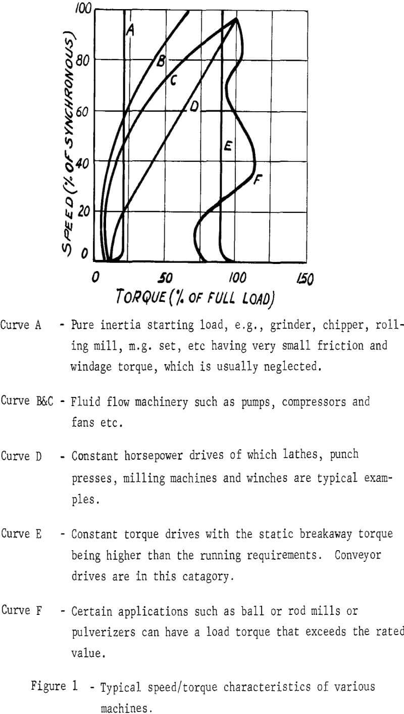
Prior to the drive selection being made it is necessary that the speed/torque characteristics of the driven machinery itself be known within a reasonable accuracy. Although this article limits itself to conveyor drives, the basic principles of drive selection remain the same irrespective of what type of machinery is to be considered, and for this reason it is interesting to be aware of possible characteristics that may be encountered.
The ideal location for the drive of a belt conveyor is the place which minimizes belt tensions both during the acceleration and running periods. Although circumstances may dictate that a drive be located somewhere between the ends of a conveyor, locating it at the head end when the conveyor has to be powered to drive it is preferred. In the case of a conveyor going down-hill where the load is overhauling and the job of the drive is to hold-back, it is better to arrange the drive at the tail pulley.
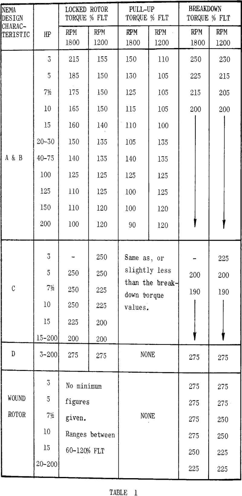
In general the speed/torque characteristics of a.c. motors up to 200 HP are defined in standards published by the National Electrical Manufacturers Association (N.E.M.A.). Motors larger than 200 HP are not covered by any particular standards and it is usually necessary to obtain pertinent information on these units from the individual manufacturers.
There are several types of starters available for providing this reduced voltage, the primary resistor and primary reactor types being standard units. There are also starters incorporating static devices such as saturable core reactors or silicon controlled rectifiers that can be arranged to adjust the motor terminal voltage, and these are often employed to satisfy applications requiring more complicated types of acceleration control. An example of what can be done is to provide a drive whose output torque remains constant at say 160% F.L.T. throughout the acceleration period. This is seen to be readily possible by imagining an infinite number of curves between the 80% and 100% voltage curves in Figure 3, and as the motor speeds up the voltage would be constantly adjusted such that the motor output torque remains at the 160% F.L.T. value.
Braking of Electrically Driven Machinery
The braking of machinery may be defined as the process of producing a retardation torque and there are five basic functions where it may be applied. These are: (a) Holding, (b) Stopping, (c) Deceleration, (d) Torque control, and (e) Speed control.
A drive which requires a brake to hold it in its stopped position is generally only used in cases where the drive would tend to move on its own were it not otherwise restrained. For this type of application the brake must be of a “fail safe” design, which means it must not have to rely on any power source to apply the brake. A friction type magnetic, solenaid or thrustor actuated unit which must be energized to open the brake and rely on a spring for closing is the type to use for this duty. If the brake is only required for holding, it need only be sized to provide the hold-back torque.
Listed below are several methods of electrical braking, some of these being more readily adjustable than others.
a) Regenerative Braking When a motor is driven above its synchronous speed by an over-hauling load condition it operates as a generator arid pumps power back into the line. The only adjustment available is to arrange for insertion of necessary external resistors in the rotor circuit of a wound rotor motor.
b) Plugging or Counter-Torque Braking The power lines to the motor are reversed to produce a reverse motor torque. When applied in this manner the motor rotor losses are high and it is essential that the duty cycle be carefully analyzed so that the motor is not damaged.
c) Dynamic Braking There are various techniques available, the overall effect being to quickly slow down the motor by causing it to act as a heavily loaded generator below synchronous speed. In order to obtain this effect some means of exciting the motor is necessary to create generator action, and any of the following systems may be employed to achieve the required excitation:
Special Coupling Types of Drives
In general, the use of a special type of coupling between the motor and load permits the motor to be started unloaded leaving the coupling device to connect and control the transmitted torque to the load shaft. The advantage of this arrangement is that the motor can be a standard NEMA design ‘B’ type, started directly across the line, voltage drops and low available torques being unimportant as the motor is starting without any connected load on its shaft. The power system must, of course, be capable of withstanding the high inrush current, but it will be of relatively short duration and in the majority of installations will not be detrimental to the operation. Once the motor is up to speed it is capable of transmitting as much as its breakdown torque through the coupling to the load without any serious disturbances to the power system.
Appendix “A”
A.C. Motor theory
General
An introduction to basic induction motor theory will enable the application engineer to obtain a better appreciation of the principles involved for the purpose of selecting the control system.
In the induction motor there are no electrical connections between the stator and the rotor, energy being transferred entirely into the rotor conductors magnetically, by induced electro-motive forces (E.M.F.) originating from a rotating field set up by the stator windings. It is this principle of operation that enables the motor to be manufactured as a robust and efficient machine, and also permits us to develop a torque equation with respect to other motor parameters.
Development of Torque
The fundamental formulae for the force (F) experienced by a conductor l cm. long, lying in and perpendicular to a field of density B maxwells per sq. cm. and carrying a current of I amperes is:
![]()
(The dyne by definition is the C.G.S. unit of force which will give a mass of one gram an acceleration of one centimeter per second per second.)
1 gram = 981 dynes
1 pound = 453.6 grams

Where
B = maximum flux density
I2 = rotor conductor current
ω = (omega) · 2 · π · f.
t = instantaneous increments of time
θ = angle that I lags behind B.
Substituting (ii) & (iii) in (i)
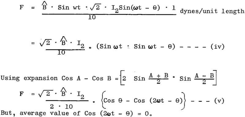
Therefore we can rewrite (v) to give us the mean force acting on a unit length of conductor per revolution.

It is evident that the total rotor torque produced by the force is:
Rotor Torque T = Total Mean Force · Radius at which force acts

Where
D = diameter of rotor
n = number of rotor conductors
Φ = flux per pole, proportional to B l
Cos θ = Rotor power factor
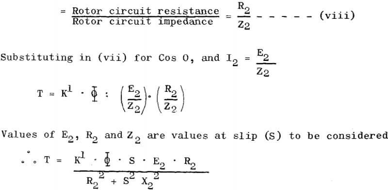
Assuming that Φ and E2 are both proportional to terminal voltage V1 (which is nearly correct), and neglecting stator losses, then,
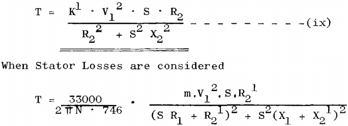
Where N = motor synchronous speed
m = no: of phases
S = slip (fractional)
V1 = motor terminal voltage
R1 = stator winding resistance per phase
R2¹ = rotor resistance referred to primary = n²(r2 + Rext)
n² = (transformation ratio)²
= (primary volts/secondary o.c.v)²
r2 = rotor winding resistance per leg
Rext = external secondary resistance per leg
X1 = stator winding reactance per phase
X2¹ = rotor reactance referred to primary = n²(x2 + Xext)
x2 = rotor winding reactance per leg
Xext = external secondary reactance per leg

Maximum Torque Determination
For maximum torque, equation (x) must be differentiated and equated to zero, from which, may be calculated the slip (S) at which the torque is a maximum.

On differentiating it is found that conditions for maximum torque are when:

Having obtained a value of S by substituting actual figures in equation (xi) it is possible to calculate the maximum torque by substituting for S in (x).
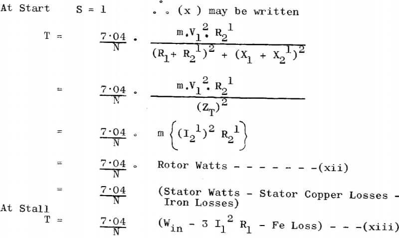
This tells us that the stall torque may be calculated by measuring total input watts and stator current if the iron losses are known. (These are usually obtained from the machine shop tests.)
It also tells us that the torque at the motor shaft is directly proportional to the watts dissipated in the rotor circuit (i.e. in the machine itself and the external secondary resistance)
Note If it is required to have maximum torque occur at starting, equation (xi) shows that the rotor resistance would have to be equal to √R1² + (X1 + X2). In general, the primary resistance R1 is sufficiently small in comparison with the reactance to justify the omission of the term R1 in this expression, hence for maximum torque at starting R2¹ = (X1 + X2¹), or approximately, the joint resistance of primary and secondary should be equal to the joint leakage reactance. Subject to this condition the current will lag approximately 45 degrees behind the impressed voltage, which means the corresponding power factor will be in the neighborhood of 70 per cent.
Running Torque
It can be shown that the torque equation (xiii) is equally true for a running machine as it is for a stalled machine EXCEPT for slip ‘S’ and friction losses. i.e. the equation would now read:
T = 7·04·S/N (Win – 3 I1 ²R1 – Fe loss-Friction Loss)……………………………..(xiv)
From this equation we can state that the torque at the motor shaft is proportional to rotor watts multiplied by slip.
Rotor Currents
In determining the most economical resistors to use in the secondary circuit it is necessary to determine the currents taken by the rotor at various steps of resistance when stalled. An equation for these currents can be obtained from equation (xii)

Appendix B
Speed-Torque Curves of A.C. Motors
In order to appreciate the full significance of the speed/torque curves of induction motors it is necessary to study the four quadrants which encompass all possible characteristics.
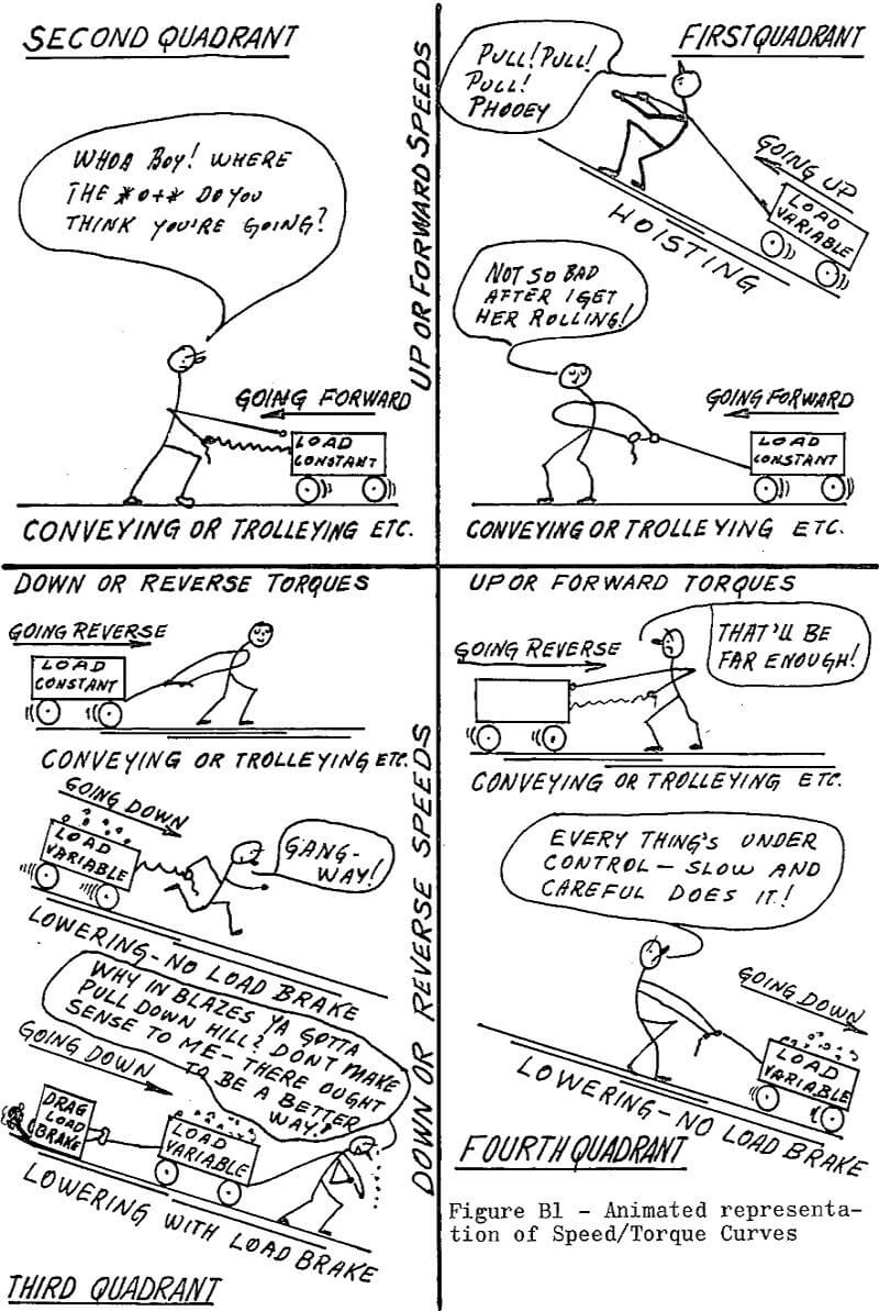
In Figure B 1 is shown a character in each of the four quadrants that represents the motor personified. His antics present a quickie of what takes place in the four quadrants as follows:
First Quadrant
This is a “pulling” quadrant.
Where hoists are concerned there is no way to get the load up except for the motor to pull it up, and this applies to any and all hoists. For most hoists, the lighter the load, the faster we go but on systems employing some type of load brake that simulates the load this is not so. In these cases our boy can pull hard but never fast.
For bridges and trolleys with motions on the level or for a conveyor that must be positively driven, the load is approximately constant. The picture shows our boy taking things kind of easy, but that is because he has the load rolling — he did have to apply some extra effort to get going.
Second Quadrant
This is a “holding back” quadrant.
No hoist performance curves will be found in this quadrant. This is because the load has no momentum to speak of and it is not necessary to force it to stop. Since it is in effect going up the hill, it will stop itself when our boy quits pulling over in the first quadrant.
It is another story in the case of bridges, trolleys, and conveyors having an overhauling load. In general, this type of drive does not stop when pull is removed. To slow down or stop a bridge or trolley drive, our boy has to hold back in other words, the motor may have to be “plugged,” which means reversing it to apply reverse torque. In the case of an overhauling conveyor the motor still holds back, but it is by “regeneration” as the motor speed exceeds its synchronous speed.
Third Quadrant
This is a “plugging” quadrant.
Trolley, bridging, and conveyor drive requirements are the same as for the first quadrant, except they are in the reverse direction.
Hoists without load brakes (counter torque, D.C. dynamic, A.C. dynamic) require a little pulling to start down when there is no load or light speed; speed is gained rapidly and our boy has to step out of the way or get run over. Heavy loads catch up quickly and our fellow has to get over in the fourth quadrant and hold back.
Load brakes add high drag, and the poor guy has to pull all the way down. This is true whether there is no load or full load, and is particularly true when electrical load brakes are used.
Fourth Quadrant
This is a “holding back” quadrant.
For bridges, trolleys and conveyors it is only necessary to hold back for retardation or stopping as was the case in the second quadrant. In this quadrant we are principally concerned with hoists, since it is lowering that causes all the problems when a.c. motors are used. It is here that the real difference in performance provided by various hoist systems are displayed, and designs ranging from extremely slow, carefully controlled systems to faster, less controlled arrangements are possible. When load brakes are employed, the motor never operates in this quadrant.
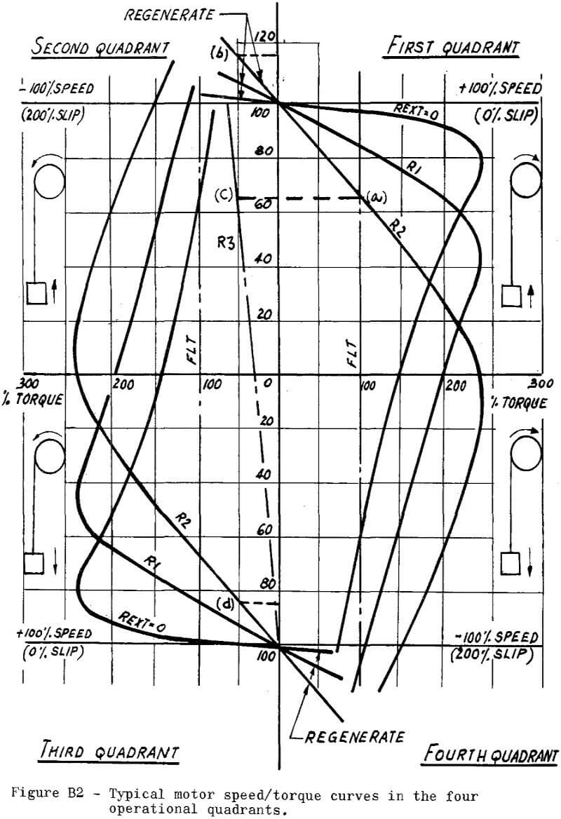
Now that the symbolic representation has presented the details that occur in each of the four quadrants, we may review these conditions with actual characteristic curves. Figure B 2 shows typical characteristics for a wound rotor motor with various increasing values of rotor external resistance from zero through R1 to R2.
It is immediately recognized that if a drive runs on step R2 at the F.L.T. condition in the first quadrant its speed would be approximately 66% of the synchronous speed at point (a). Without making any changes to the motor, but reversing the load to an overhauling condition of say -50% F.L.T., the motor speed would automatically adjust to hold the load back at about 115% of synchronous speed by regeneration at point (b). If at this time it is desired to return to the 66% speed condition, then the motor terminals can be reversed to plug the drive, and the rotor external resistance be increased to a value R3. The speed will stabilize at the required value at (c) but it is obviously not an ideal condition as very small load changes will result in large swings in speed. Reversing the motor and remaining at the rotor external resistance condition R2 would immediately transfer to the R2 curve in the second quadrant and the motor speed would be forced to zero along this curve at which time it would reverse and drive the machinery in the opposite direction to the point that the R2 curve intersects with the 50% F.L.T. line in the third quadrant to maintain a speed of 85% at point (d). Conditions that can occur in the fourth quadrant duplicate those described for the second quadrant.
Appendix ‘C’
Fundamental Mechanics
In all drive application considerations it is necessary to interpret the mechanical characteristics of the driven equipment in terms of the drive requirements. The formulae required are readily available in standard handbooks or mechanical text books but are generally given in absolute units. The following describes the most useful mechanical formulae, expressing them in readily useable engineering terms. Most of the data is given or can be derived from the basic fundamental formulae for rotation and translation.
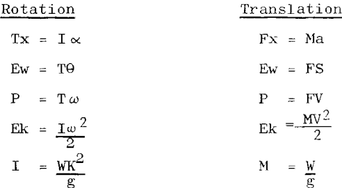
Rotation: HP – Torque – RPM Relation
The common unit of power (or rate of doing work) is the “horsepower”, which is defined as 550 Foot-Pounds/Second or 33000 foot pounds/minute. Expressing the fundamental equation for power in terms of this unit we obtain
HP = Tω/550
Expressing angular velocity in the common terminology for motor speed – RPM
ω = 2π RPM/60
and substituting in our equation for horsepower
HP = T:RPM:2π/550:60
= T:RPM/5250
Usually the HP rating of a machine and the speed is known and it is necessary to determine the torque
T = 5250.HP/RPM
A useful “rule of thumb” to remember is that one HP at 1750 RPM is equivalent to three lb. ft. torque. By ratioing HP and RPM the torque of any motor can be estimated mentally.
Translation: HP – Force – Velocity
Expressing the fundamental equivalent translation formula for power in the “horsepower” unit as above
HP = F · V/550 or F·FPM/33000
This relationship is useful in determining the belt horsepower of a conveyor drive the force F being the effective belt tension at the driven pulley.
Rotation: Acceleration Torque – Time Relationship
One of the most frequent problems that arises in the application of drives is the torque or time required to accelerate a motor and the equipment it drives. A simple formula can be derived from the fundamental equation
Tx = T∝ = I dω/dt
Assuming that torque is constant during acceleration
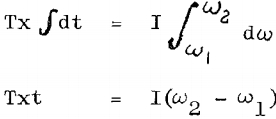
substituting for

The limitation of this formula should be carefully noted
- Constant torque was assumed in the above calculations. In general with a.c. drives this is not the case, and it has been found that using average values of accelerating torque introduces an error into the solution. For small torque variations the error in time will be small, about four percent low for two to one torque variations and ten percent low for three to one.
The accelerating time may be very accurately calculated by breaking up the speed torque curve into segments, each segment with a low torque variation. Using average torques for each segment the individual times may be independently determined and totalized to obtain the total accelerating time. - The total motor torque includes friction and load torques as well as the accelerating torque. In determining the accelerating time the friction and load torques must be subtracted from the total motor torque to determine the torque available for acceleration. Conversely if the acceleration torque has been determined friction and load torques must be added to determine the required motor torque.
Translation Accelerating Force – Time Relationship
By starting with the relation Fx = Ma and proceeding as shown under the preceding section it can be shown that
t(time to accelerate in seconds) = W(FPM2 – FPM1)/1932 Fx
The same general limitations as discussed in the previous section should be considered in the application of this formula. Friction and load forces must be considered in determining Fx or total force. Where Fx is not a constant the speed force curve should be broken up into segments and the times individually calculated to obtain the total time accurately.
Stored Energy
In working with loads of high inertia it is convenient to determine the stored energy in the system, and generally simplify the approach to problems of acceleration torques. Referring to the fundamental formula
Ek = ½ Iω²
or Ek2 – Ek1 = ½I (ω2² – ω1²)
expressed in Horsepower Seconds

Substituting for ω and I as before we can find the stored energy at operating speed.
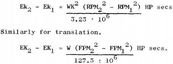
This method of approach can also be used to solve problems of acceleration and deceleration of inertia loads. For a change in speed the change in stored energy of the system is given by the equation above. This change in energy can be equated to the acceleration energy delivered to the system (or deceleration energy absorbed). Assuming constant torque the average power will be
Px (ave) = Txω2 – Txω1/2 lb.ft./sec.
Multiplying by time we can obtain the kinetic energy required for acceleration (or deceleration)
Ex(ave) = (Txω2 – Txω1)t/2 lb. ft. = (Txω2 – Txω1)t/1100 HP Sec.
substituting for Tx = 5250 HPx/RPM and ω = 2π RPM/60
and equating to the change in stored energy
(HPx2 – HPx1)t/2 = WK² (RPM2² – RPM1²)/3.23 · 10 6
The majority of problems involve acceleration from rest where HPx1 = RPM1 = 0. In this case
HPx = WK² · RPM²/1.615t · 10 6
Where HPx equals the accelerating HP (not including friction or load HP) at the operating speed to which the drive has been accelerated. The per unit accelerating torque can then be determined as HPx/Rated HP
or the actual value of accelerating torque is determined by
Tx = HPx : Rated Torque/Rated HP
This assumes that both accelerating horse power and torque remains constant throughout the acceleration period. When this is not the case the same limitations already outlined under the heading “Rotation: Acceleration Torque – Time Relationship” apply.
Note: It has been shown that in accelerating an inertia load the energy supplied to the system, not including friction or load losses, is equivalent to the stored energy at operating speed. It has also been shown that this energy is equal to ½ the accelerating HP at operating speed times the accelerating time.
When considering the differences between the HP input and HP output of a drive system, this is produced as heat in the motor rotor circuit or in the fluid of a fluid coupling or in the clutch plates of a friction coupling and is equal to the power delivered. In other words, the accelerating loss in all slip- type devices is equivalent to the stored energy of the system.
Similarly it can be shown that in plugging a motor to a stand-still the rotor losses are three times the system stored energy and for a full speed plug reversal the losses are four times the stored energy.
Equivalent Inertias
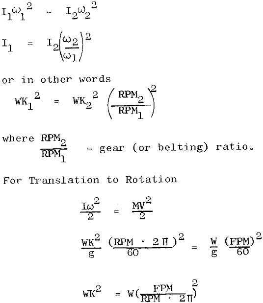
Motors are often geared or belted and different parts of the machine may operate at widely different speeds, or alternatively the motor may drive a body in straight line motion through a rack and pinion or rope and drum drive. It is then desirable for calculation purposes to obtain all of the system inertias in terms of equivalent WK² on a common shaft.
To transfer inertia use the law of conservation of energy and equate the stored energies.
For Rotation to Rotation
Optimum Gear Ratio
There are a number of drives where it is necessary to select the optimum gear ratio for minimum acceleration time. Generally complete data on the load is known and a tentative motor size selected.
WL = speed of load
IL = load inertia
TL = Load torque = R.TM
WM = speed of motor
IM = motor inertia
TM = motor torque
R = gear ratio motor to load = WM/WL
t = accelerating time in secs.
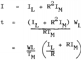
To find the optimum gear ratio differentiate time with respect to gear ratio and equate to zero
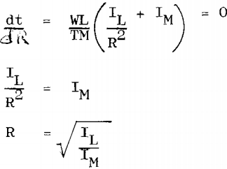
The above is true only for drive with a light friction loading. If the friction loading is appreciable it will affect the optimum gear ratio as follows:
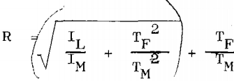
where TF = friction torque referred to motor shaft.
Appendix ‘D’
Sample Acceleration Time Calculation
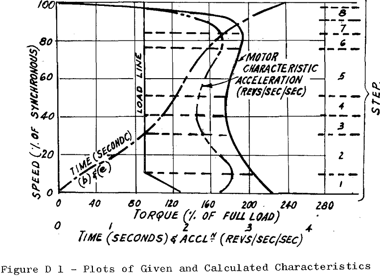
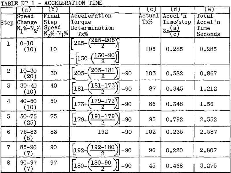
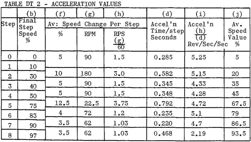
Drive – Conveyor (load characteristics as in Figure D1 below)
Motor – 15 HP, 1800 RPM, TEFC, NEMA Design ‘C’. WK² = 1.78 lb ft²
Load – Constant torque at 90% FLT of motor with
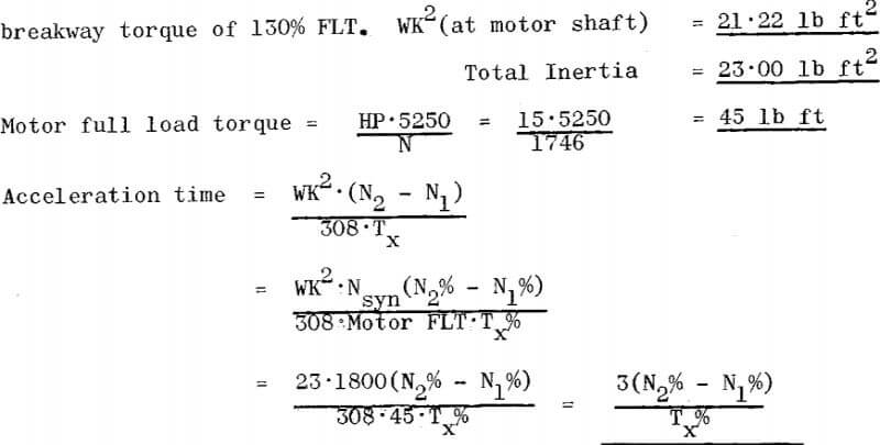
This is the factor used in Column (d), Tables DT1 & DT2
