Table of Contents
Natural materials can be used successfully in the construction of heap leach pads. The use of these materials usually result in the least expensive approach for such facilities. Sufficient geotechnical experience has been gained in the design and construction of clay heap leach pads so that they can be used with confidence.
Requirements of Pad Materials
Heap leach pad materials must satisfy the following requirements:
- Permeability. The coefficient of permeability of pad material must be sufficiently low to prevent loss of leachate and therefore precious metal values.
- Cost. There is a number of materials which can be considered for pad construction; these include: PVC, Hypalon, HDPE and other synthetic membrane type liners; rubberized asphalt which can be sprayed onto a prepared base; and soil cement or hydraulic asphalt cement.
- Pad Construction Considerations. A single use pad will require a different set of criteria than a pad which will be used for more than one leaching cycle. It is possible to re-use a clay pad; however, care must be taken not to damage the pad during the removal of heap material.
- Heap Construction Considerations. The heap can be constructed by stacking the ore with front-end loaders, using belt stackers or through end dumping and dozing.
Design of Material Mixture for Clay Pad
The soils beneath the site are generally stratified alluvial sediments deposited as a fan to a depth of about 60m. The upper portion of the subsoil contains layers of caliche, ranging in thickness from 3mm to 600mm.
- Index Tests such as grain size analyses and Atterberg Limits.
- Compaction Tests.
- Permeability Tests.
It is recommended that the whole test series be repeated for all the clay mixtures used in the design process. This will help in detecting inconsistencies in the results and will allow interpolation and in some cases, extrapolation of trends. It is especially important that the permeability tests be performed on samples compacted to the same standards; otherwise, it is very difficult to compare the results from tests on the various clay mixtures and to relate the results to the expected field behavior.
It must be noted that, in general, the characteristics of the in situ soil and the clay type used as an admixture, determines the mix design. However, as a general rule of thumb, 5% bentonite is usually sufficient to lower the permeability of the mixture sufficiently. This value can be used in feasibility analysis for the comparison of natural liners with synthetic liners when suitable clays are not available on site.
Construction of Pad
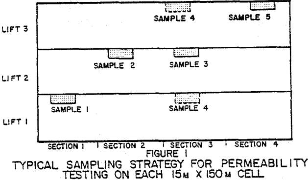
The total pad area of 43 acres is to be constructed over the four-year life of the project. It was therefore constructed in cells, with dimensions of about 15m by 150m. The procedure described below was followed for the three lifts of each cell. It is common to construct more than one cell at a time or to have adjacent cells in various stages of completion. Sufficient continuity is obtained between the cells due to the disc used for mixing the materials.
After compaction of the bottom lift, its final surface is leveled with a blade and bentonite noodles are spread to a thickness of about 15mm. This is followed by the addition of 50 to 75mm clayey silt and 100 to 125mm of stockpiled site soil.
It is preferential to have good bonding between the different layers of the pad to eliminate interfaces of preferential seepage. This is usually difficult to obtain with a smooth-wheeled roller unless the top of the previous layer is scarified. Sheepsfoot rollers enhance good bonding.
Construction Quality Control
Quality control testing is performed on each lift. A nuclear gauge is used to perform moisture content and density measurements. Such measurements are taken at ten locations on each constructed cell layer. Only one measurement is allowed to be outside the ranges specified below.

Most of the compaction control tests satisfied the specifications. Initially, some problems were experienced with moisture contents exceeding the upper limit, although the densities were satisfactory. These results were not of concern, as it is known that lower permeabilities are obtained if the soil materials are compacted wet of optimum.
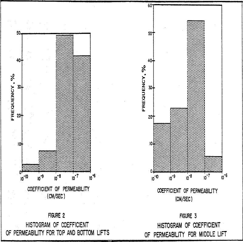
Permeability testing of low permeability materials is very time-consuming due to long saturation times and the low percolation rates during testing. In this project permeability testing was part of the quality control requirements and results had to be obtained before construction of the next lift. It was therefore important to select a reliable testing procedure which is relatively fast to perform and gives repeatable testing results.
Test specimens are removed from the constructed pad in specially machined sampling rings. These rings have a diameter of 71mm, a height of 50mm and a thin cutting edge. Sampling is done directly after the constructed lift has satisfied the moisture-density testing criteria. Specific care is taken in cutting the specimens and it is common to take one or two more specimens than required to have extras in case of specimen destruction during laboratory preparation.


Investigation of Pad after Leaching of First Heap Area
The waste discharge permit required an investigation of pad integrity after completing the leaching cycle on the initial heap areas. The purpose of this investigation was to determine whether any leachate penetrated the pad. Such an investigation can be made by taking samples during drilling operations or excavating the area and inspecting the subsoil in test pits. Drilling and sampling are difficult because of access to the heap and problems in retrieving undisturbed samples of the silty sand subsoil. Another concern of drilling is the possible contamination of samples during sampling. To insure reliable samples, the procedure described below was followed.
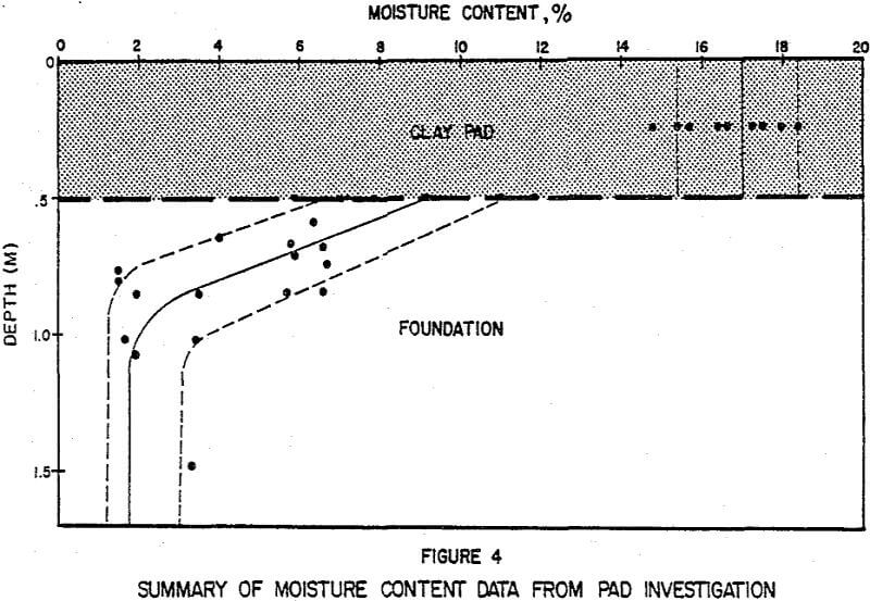
Nine other sample holes were dug using a backhoe to make a small trench. Samples for moisture determinations and cyanide assays were collected at the pad surface, immediately below the pad, just above the moisture front/dry soil interface and below the moisture front. The location of the wetting front was easy to observe because of the clear change in soil color.
It appears that the first two reasons provide the most likely explanation for the increased moisture level found below the pad. It would be expected that penetration of the pad by leach solution would be followed by an increase of moisture content in the pad. Such an increase did not occur since the moisture contents during


