Table of Contents
- Demonstrations at Sunnyside Mine No. 1
- Advancing Tailgate of 10 Left Longwall Panel
- Double-Entry Tailgate of 17 Left Longwall Panel
- Demonstrations at the York Canyon Mine Double-Entry Tailgate of 8 Left Longwall Panel
- Demonstrations 3 Through 6
- Demonstrations 1 Through 6 Summary
- Experimental Sections at Other Mines
- Bethlehem steel Co., Van No. 131 Mine
- United States Steel Corp., Gary No. 9 Mine
- Texasgulf Co., Trona Mine, Rock Springs Area of Wyoming
- Snowmass Coal Co., Thompson Creek No. 1 Mine
- Design Guidelines Support, Cost, and Installation
- Support Criteria
- Cost
- Installation Procedure
- Industry Acceptance
- Commercial Design 3 SFC Members
- Conclusions
This research is a part of an ongoing effort by the Bureau of Mines to improve health and safety in coal mining as directed by the Federal Mine Safety and Health Act of 1969 and amendments of 1977. The concrete crib design and field testing project has evolved from laboratory research to a verification and demonstration phase for technology transfer to industry. Cooperative underground demonstrations are either in progress or completed in seven different coal mines and one trona mine. Demonstrations involved three different steel-fiber-reinforced concrete (SFC) support member designs. These will be referred to as designs 1, 2, and 3.
A successful installation of design 1 SFC cribs at Kaiser’s Sunnyside Mine No. 1 at Sunnyside, Utah, was made in 1976 and monitored through 1979. It was a test section in the Bureau’s single-entry longwall (LW) demonstration. The wood cribs used to support the combined gate, or dual-gate, single entry were not stiff enough to hold the tailgate portion open in a satisfactory manner after the passage of the first longwall face, but the SFC crib test section supported the entry satisfactorily. Design 1 members contained steel rebar that was eliminated in later designs. This report covers field testing of SFC designs 2 and 3.
The encouraging results of design 1 prompted further work to refine the SFC support members to a design 2. The principal advantages of the revised design were a more versatile block geometry amenable to a high-speed production in a range of sizes, a lower cost mix design, and a more efficient fiber. Enough hand-molded members were produced in a small-volume production run to start the first few experimental sections. A 2.9-to-1 cost advantage was shown for the SFC system based on equal support capacity compared to wood.
Design 3 is very similar to, and based upon, design 2. Working with U.S. Steel and Bureau of Mines researchers, Burrell Construction & Supply Co., New Kensington , Pa., developed a commercial design that has been mass-produced. The manufacturing cost was greatly reduced from that of design 2 by use of a standard concrete block machine modified for this purpose. Reduction of transportation costs is anticipated when manufacturers closer to the mining areas begin production as demand increases. SFC support systems will cost less when increasing confidence in SFC support capacity permits increasing the crib spacing. Initial installations are customarily started at less than optimum support spacing for safety reasons and, therefore, cost more than actually necessary.
The main portion of this report will discuss SFC support system demonstrations in applications such as—
- Support of multiple-entry longwall tailgates until the rear of the second longwall face supports has arrived.
- Long-term support of longwall tailgates, bleeders, returns, and return escapeways.
- Support of an advancing tailgate with a pair of continuous SFC crib walls.
- Use as a stiffer stopping material that requires less maintenance.
- Other potential uses include (1) long-term support of shaft pillar areas and (2) better ground control in room- and-pillar retreating operations in main and bleeder entries.
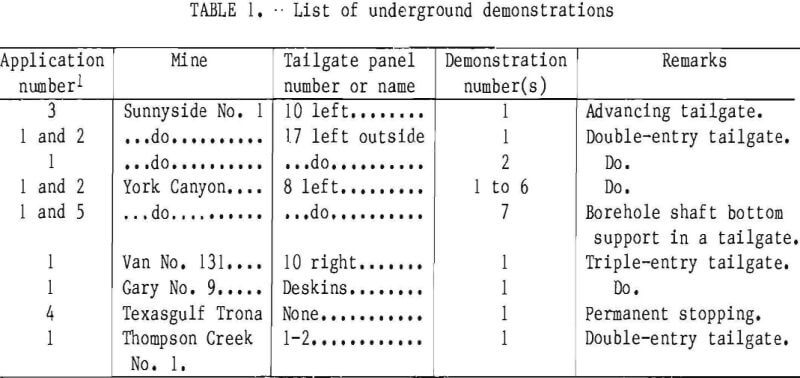
Table 1 lists applications demonstrations by mine order.
Demonstrations at Sunnyside Mine No. 1
Kaiser Steel Co. cooperated in several demonstrations at Sunnyside Mine No. 1 property. In addition to the design 1 installation previously mentioned, demonstrations of design 2 took place in the 10 left longwall panel and the 17 left outside longwall panel.
Advancing Tailgate of 10 Left Longwall Panel
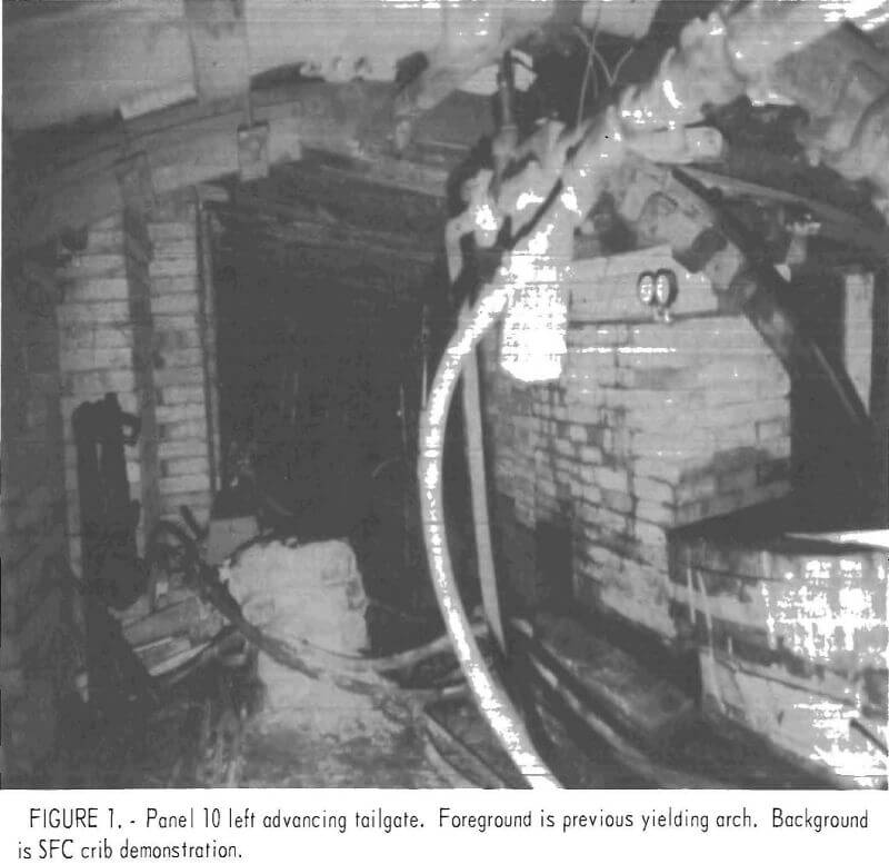
Paired continuous walls of design 2 SFC solid cribs placed “skin-to-skin” were installed in the advancing tailgate of the retreating 10 left longwall panel (fig. 1). The walls demonstrated application 3, support of an advancing tail-gate. The panel had about 2,000 ft of cover. The demonstration was not completed because the panel was stopped for production reasons not related to the concrete cribs. It was stopped with about 40 pct of the test section completed, when the face was 37 ft from the first pair of cribs installed.
The primary purpose of the demonstration was to obtain loading and performance, rather than economic information.
The standard advancing tailgate of the 10 left longwall consisted of yielding arches prior to the start of the SFC test section (fig. 2). Sixteen-foot-diameter semicircular arches on 3-ft centers had wood cribbing on both sides. Floor heave and punching into the floor caused loss of tailgate entry clearance, necessitating floor removal. Initial 7-ft clearance at the center of the arches closed to 4 ft or less at some places. The actual layout of the demonstration is shown in figure 2.
Individual cribs with dimensions of 30 by 30 by 72 in consisted of concrete members plus ½ to 1 ft of wood wedging and blocking. Most blocking was at the top of the cribs. Only enough wood wedges were used on the bottom to fill in and level the base. The cribs consisted of solid layers with members crosswise to members in the layers above and below. Each individual design 2 member measured 30 by 3 by 10 in.
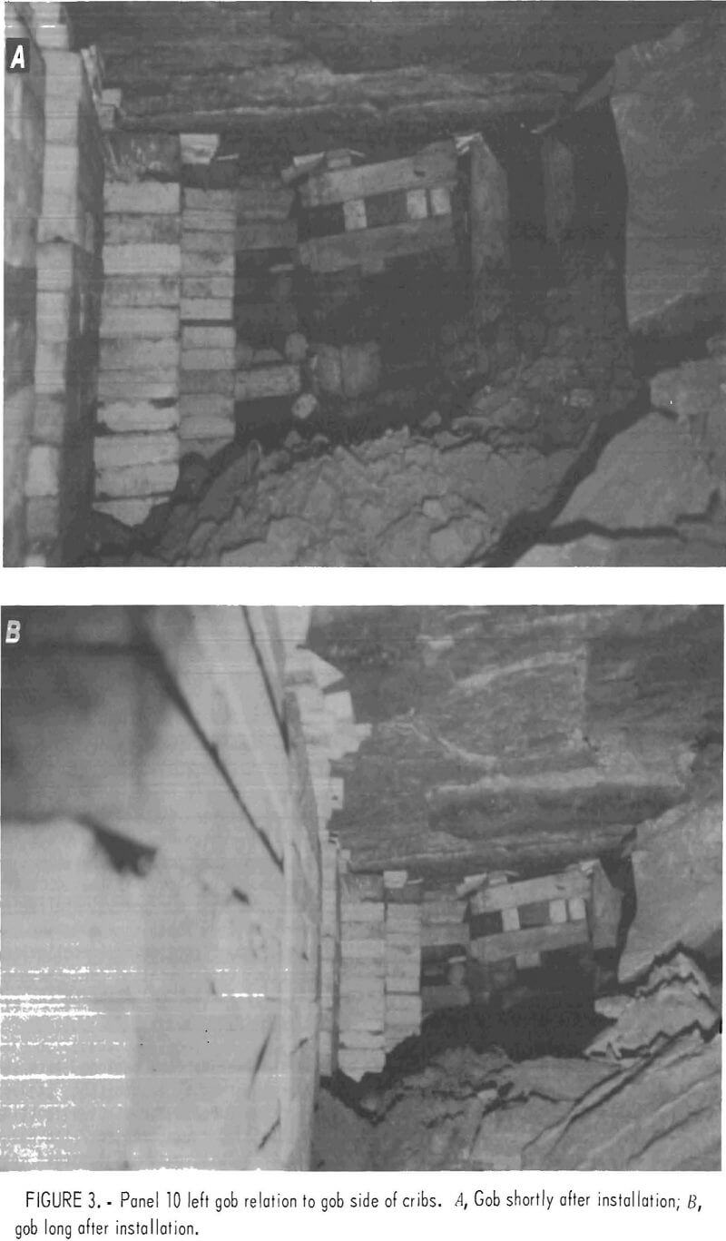
Construction started with the first pair of cribs. Subsequent crib pairs were offset to the right until the desired location closer to the remaining coal pillar was obtained (fig. 2). A space of 5-½ ft was maintained from the rear of the chock to a completed crib. Roof-bolt mats were installed on 4-ft centers before crib construction and spanned the 8-ft clearance between crib walls. A hydraulic jack behind longwall chock 5, on the gob side of the SFC crib, provided insurance against premature caving into the crib construction area. The gob-roof break line did not approach closer than 4 ft to the gob-side crib at a distance of 15 to 20 ft behind the chock at the slowest average rates of advance. At faster advance rates, the gob-roof break line lagged even farther behind before coming within 4 ft of the crib. At the point of crib construction, the gob-roof break line was normally about 10 ft from the gob-side crib (fig. 3A). When the panel stood for a month with no advance, small pieces of gob had piled against the side of the cribs (fig. 3B).
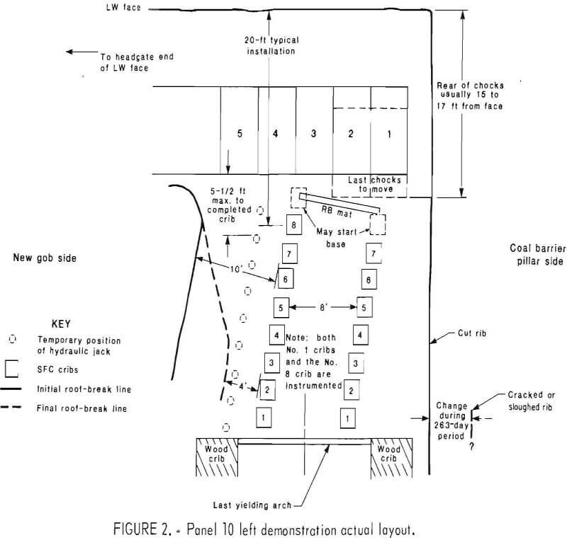
The purpose of the 8-ft clearance between crib walls was to provide clear-ance for a small battery-powered supply vehicle. The narrowest possible tailgate was desired, as close as practical to the barrier pillar, to minimize the loads on the cribbing.
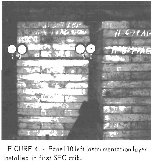
Three SFC cribs were instrumented with four hydraulic load cells per crib. The first two cribs were instrumented, as was the last one on the gob side. The four load cells constituted a complete layer in the crib such that the sum of the loads on the four equaled the total load on the crib. Each load cell installation consisted of a layer of rubber conveyor belting, hydraulic flat-jack load cells with pressure gages, and another layer of conveyor belting (fig. 4).
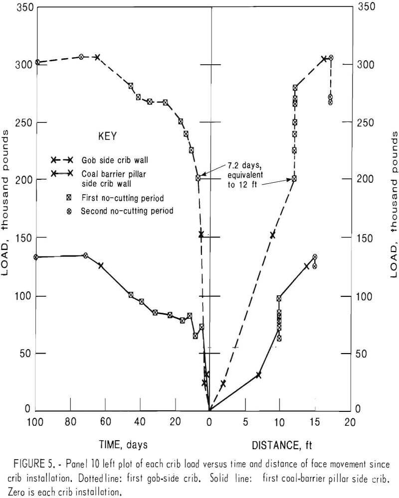
Figure 5 shows the data plots of the first two instrumented cribs. The total load on each crib is shown versus time and face movement distance after crib installation. Note that during the first 7 days, loading increased proportional to face movement distance. Typical distance from the face to any crib installation was about 20 ft. Total face movement was 17 ft after first crib installation. Seven cribs were installed on the coal barrier pillar side, and eight on the gob side.
Two interesting time periods were ob-served owing to the intermittent production of this panel. The first no-cutting period of 39 days showed an increased load on both crib rows. The second no- cutting period of 239 days showed slow unloading.
Assuming the higher loads of the gob-side crib row to be most indicative of rock mass behavior, fast loading occurred with fast cutting, slower loading occurred with slower cutting, and slower or no loading occurred during the first no- cutting period. During the second no-cutting period of 239 days, unloading appeared only slightly faster near the end of the period and there may not be a significant difference. Information recorded here showed increased load during successive coal excavations. The maximum crib load during the demonstration was 305,000 lb, or 340 psi on the first gob-side crib. The other instrumented gob-size crib No. 8 at the rear of the chocks, never changed from the zero reading. The maximum crib load on the pillar side was 135,000 lb, or 150 psi on the first crib, the only instrumented crib on that side. The load per linear foot of entry was 109,000 lb on the gob side and 48,000 lb on the pillar side, or a total of 157,000 lb/lin ft of entry. The integrity of the tailgate entry was maintained at these loads. Cribs were still intact with no cracks, had maintained their shape, and were not punching the roof or floor. Wood blocking and wedging had squeezed to accommodate the 1 to 3 in of closure.
Total load on a crib was about proportional to the distance from the barrier pillar. During the 239-day no-cutting period, the gob-side load was decreasing four times as fast as the pillar-side load, when the data from the two instrumented cribs were analyzed. This trend was attributed to (1) lessening of the cantilevered gob-roof load as the cave line progressed closer to the gob-side crib wall, (2) support of the remaining cantilevered gob roof by the accumulating caved gob, and (3) sloughing out and cracking of the coal pillar, tending to equalize the distances from the pillar to both crib rows.
A summary of the facts and conclusions documented by instrumentation and visual observation in 10 left advancing tailgate follows:
- Loading of each of two instrumented cribs was in proportion to the distance of movement of the longwall face and chocks after crib installation-
- Total load on each instrumented crib was about proportional to the distance of the crib from the coal barrier pillar.
- Stopping the longwall face advance caused an immediate and drastic drop in the loading rate. The loading rate decreased, and finally the load peaked and began to drop gradually (figs. 5-6).
- A trend toward equalization of the load on the two walls occurred with time.
- If the maximum load can be with-stood satisfactorily, it is likely that the integrity of the entire tailgate can be maintained for the life of the panel, and supply through the tailgate can be maintained. The highest load recorded during the demonstration was 157,000 lb/ lin ft of entry.
6. Integrity of the tailgate was maintained for the 10 months observed. The maximum 340 psi observed on the crib- bearing surface was far below the 3,000+ psi capacity of the SFC cribs.
7. At 37 ft behind the longwall face, the design 2 SFC crib wall system appeared superior to the yielding arch system previously used. Superiority was attributed to the increased bearing surface at the floor of the SFC cribs, compared to that with arch legs.
8. Roof sag between the crib walls in the 8-ft clearance width was insignificant at 37 ft from the final face. Rock- bolt (RB) mat on 4-ft centers was sufficient support to prevent sag.
9. Hydraulic gage instrumentation did not fail.
The method of crib construction was satisfactory. Two cribs were installed as easily as one yielding arch. Little floor cleaning was necessary to build the crib base behind 1 chock if it was built as soon as the chock was moved.
Hydraulic jacks satisfactorily supported the maximum 5½-ft space between chocks and completed cribs while construction took place. Newly constructed SFC cribs did not take load until the adjacent chock was moved ahead; then the crib took load.
The second crib from the chock was loaded tightly enough to prevent loosening or destruction of the crib from caved gob that later piled against it. Normally, gob did not pile against a crib until it was 15 ft behind the chock, 4 days later at the normal advance rate.
11. During the final 239 days of in-activity, load was dropping four times faster on the gob side than on the pillar side.
12. An SFC crib system demonstration longer than 50 ft, preferably over 100 ft, would be useful in the final evaluation of the system for advancing tail-gates. Indications are that there should be twice as much gob-side crib bearing area as there is for the pillar-side cribs.
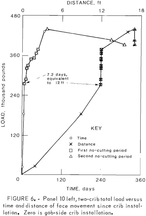
13. The combined load of both crib rows plotted against distance of face movement after crib installation shows as a line of nearly constant slope, except when cutting was suspended for long periods of time. Load was proportional to that distance after installation but not to time from installation (fig. 6).
Double-Entry Tailgate of 17 Left Longwall Panel
Two short, design 2, demonstrations of less than 50 ft in length were installed in the retreating 17 left longwall panel tailgate, half of a double-entry (DE) system. The panel was located between the vertical person-shaft borehole and the hoisting slope for track access to the area. The depth of cover is about 1,000 ft. Two longwall faces, 16 left and 17 left, affected the double-entry tailgate, which was between the two panel face area. The 16 left face was about 800 ft ahead of the 17 left. Observable effects of the 16 left face influence were limited to occasional local roof and rib sloughing of the 17 left tailgate. The wood crib pairs were installed 100 ft or more ahead of the 16 left face.
Demonstration test sections of SFC cribs showed no change from zero load on the instrumentation when 16 left went by the demonstration locations. Both of the demonstrations were at the intersections of crosscuts. The short demonstrations were a severe test for two reasons: (1) Intersections transferred greater loads to the supports than in nonintersection
areas, and (2) the demonstrations were so short in length that the stiffer concrete cribs took more than their share of the load.
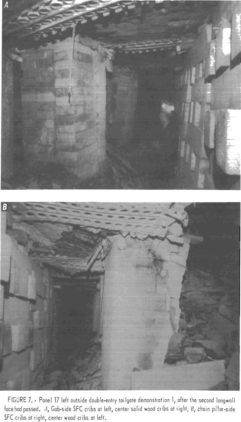
The first demonstration related to (1) normal or short-term longwall tailgates allowed to cave at the rear of chocks, and (2) long-term tailgate support for exhaust ventilation to the end of the complete panel. Four pairs of SFC cribs substituted for paired wood cribs, as shown in figures 7A, 7B, and 8, a 20-ft-long test section. Both SFC cribs in the first pair were instrumented.
Compared with the wood crib system, the gob-side concrete crib row was offset away from the face so the shearer would not have to cut it as sometimes occurred with the wood cribs on the gob side. There were 270 sq in of SFC crib support- bearing surface per linear foot of entry length.
A 12-ft clearance between paired wood cribs was maintained. Hydraulic jacks, occasional wood posts, and occasional wood cribs were added in the tailgate entry about 50 ft ahead of the longwall face. Mine experimentation with
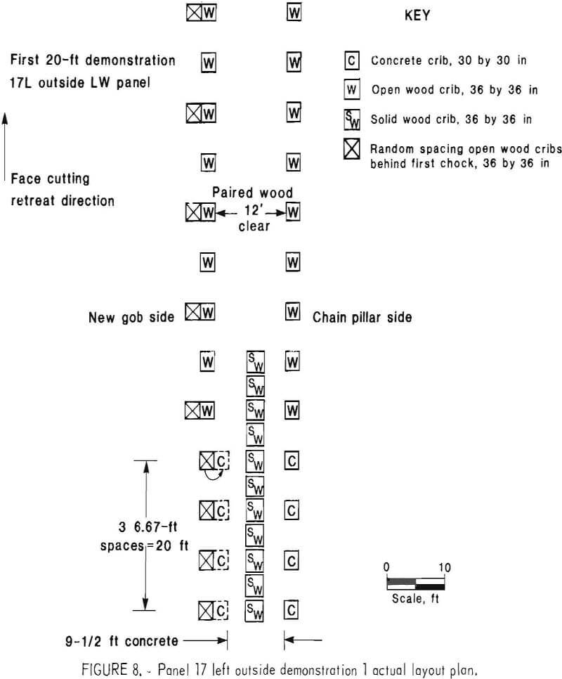
application 2, long-term tailgate support, began at the start of the 17 left panel. An attempt was made to keep the double-entry tailgate entry open for exhaust ventilation until completion of panel 17. To accomplish this, an additional continuous solid-wood crib row was placed in the center of the tailgate. A random-spaced row was also placed behind the last chock, on the gob side, as the 17 left face retreated. These two additional wood crib rows had little effect on the performance of the stiffer concrete cribs. After the first demonstration cribs were passed by the 17 left face, the double-entry tailgate support attempt for application 2 was discontinued because the wood cribbing was unable to maintain an adequate ventilation area.
Construction and instrumentation of individual SFC cribs in the 17 left tailgate were the same as previously described for the 10 left panel.
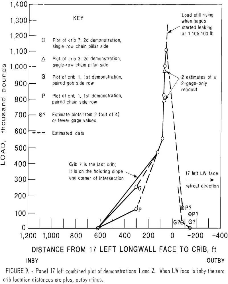
Figure 9 shows crib load versus distance from the 17 left face for demonstrations 1 and 2. The limited instrument information from the first demonstration, indicated by “G” and “P” on the plot, was in general agreement with the more plentiful information from demonstration 2 and was therefore combined with it. Note that the 2:1 load ratio for the gob-side crib loads compared with coal pillar-side crib loads, as was observed in the 10 left advancing tailgate, was also observed immediately at 300 ft in the first demonstration in 17 left. It was estimated, if gages had been read more often, loading would have started about 450 ft prior to arrival of the 17 left face.
As seen in figure 7A on the center rear crib, most vertical joint cracks in the SFC cribs were parallel to the tailgate entry. There were three times as many parallel cracks as there were perpendicular. Each crack was three times as wide at the top as at the bottom of a crib. Maximum separation observed at the top was 12 in when the 17 left face had passed the crib by 135 ft, contrasted with 6 in when the face had gone by 71 ft. These cracked cribs were functioning as three minicribs after the 17 left face had passed by 135 ft.
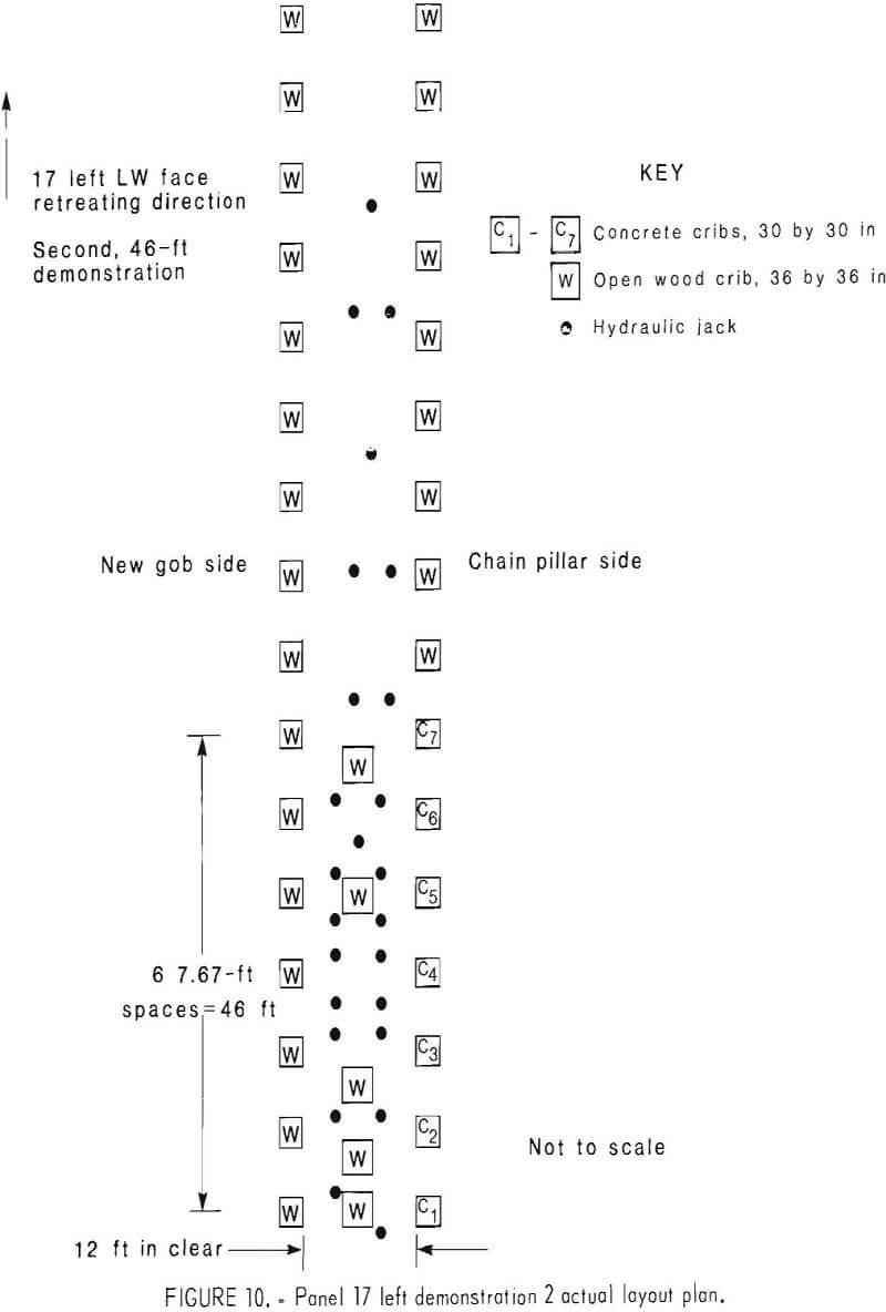
The second demonstration in the 17 left outside tailgate was 46 ft long. It pertained only to application 1—support of multiple-entry tailgates until the rear of the second longwall face supports has arrived. The demonstration consisted of seven SFC cribs that were substituted for the wood crib row on the chain pillar side only (fig. 10). Each SFC crib had an open wood crib paired with it. All paired cribs were installed prior to arrival of the 16 left face. SFC cribs 3 and 7 were instrumented. The clearance between the two crib rows was maintained at 12 ft. Because the wood crib was on the gob side, there was no need to offset it to avoid cutting by the shearer. As usual, temporary support was installed 50 ft before the arrival of the 17 left face. At this intersection, additional support consisting of open wood cribs was placed as a center row between the pairs at approximately the crib 1, 2, 3, 5, and 7 locations. Other center areas between the crib rows were supported by individual hydraulic jacks for 50 ft ahead and 20 ft behind the 17 left face.
Construction, instrumentation, size, and supply of individual SFC crib members were similar to those in the first demonstration.
Figure 9 shows the combined information of both demonstrations. Loads were rapidly increasing when the gages began leaking, so loads much higher than recorded were probable. Loads at the two intersection corners, cribs 3 and 7, were in agreement. The last recorded reading on crib 7 was 1,105,000 lb, or 1,230 psi, when the 17 left face was 52 ft from arriving at crib 7.
The worst cracking of SFC cribs was the same as in the first demonstration. Cracking was parallel to the entry at the joints between members placed parallel to the entry. Cribs 1 and 2 were cracked all the way through from top to bottom. There were four cracks parallel to the
entry and none completely through perpendicular to the entry, when the 17 left face was 6 ft from arriving at crib 1. The effect was attributed to differential roof and floor movement across the entry. In relation to the floor, the top of the crib appeared to move toward the chain pillar. There were three times as many, joint-cracked members in crib 3 as in 7, indicating that crib 3 had probably reached higher peak loads than crib 7 at some time.
The last visual observation of demonstration 2 indicated that roof punching averaged about 3 in. After demonstration 1, roof punching at the demonstration area was an average of 10 in at both crib rows. Indications were that concrete cribs, as used, would not punch severely enough to break the integrity of the originally bolted roof while normal functions were completed at the double-entry tailgate. The point must be made that the two demonstrations were extreme
because they were so short in length that concentrated end loads predominated. An entire entry supported by the SFC system will probably show more favorable average effects than those observed in the two demonstrations, for both damage to the cribs and punching effects.
A summary of the information and conclusions documented by the instrumentation and visual observation in the 17 left double-entry tailgate follows:
- As loading of the concrete cribs started, total loading of a crib was about proportional to the crib distance from the coal chain pillar.
- All the damage effects likely would have been less if the 17 left face was not following the 16 left face so closely, and if the demonstrations had been greater in length, the majority of support would have been unaffected by high end loads caused by the sudden transition from the soft wood support to the stiff SFC cribs.
- Maximum measured and recorded load for only the SFC cribs was 144,000 lb/lin ft of entry, or 1,230 psi for the bearing surface of the crib. The maximum load on the cribs occurred when instrumentation was not read, or had failed.
- For the application 1 purpose of maintaining a multiple-entry tailgate only until the rear of the second long- wall face supports had arrived—
a. Paired open wood cribs plus jacks were sufficient support in the 6-ft seam height.
b. In the demonstrations, one SFC row plus jacks was sufficient. The gob- side wood crib row effectiveness was destroyed by the shearer.
c. Two SFC rows on the normal spacing of cribs were sufficient support.
d. Integrity of the double-entry tailgate was maintained with either of the systems above, SFC or wood. - At 135 ft after the 17 left face had passed, the following observations pertaining to application 2 were made for the purpose of maintaining a multiple- entry tailgate for a return until the panel is finished:
a. Paired SFC cribs with a wood continuous solid-crib row between them were still maintaining the integrity of the tailgate.
b. The SFC cribs were still resisting load, considerable damage had accumulated, and the damage was still increasing. At 200 ft, the wood crib system was not sufficient support.
c. Roof punching effects were equal on both rows. Loading had exceeded roof bearing strength at most cribs. Accumulated debris may have masked lesser floor punching; there appeared to be none.
d. A subjective judgment was that at least one solid continuous wall of SFC cribs for increased bearing surface would be necessary for this extreme application 2 support.
e. A much longer demonstration is needed to prove or disprove the suitability of the SFC cribs for application 2. - Crosswise members in alternating layers are needed to hold the crib together laterally.
- The mining company preference for a one-on-one replacement of wood cribs resulted in higher cost. The higher cost arose from the increased handling of 72 pieces for an SFC crib, compared to 14 pieces for a wood crib. Because SFC cribs are many times stronger and stiffer, the simple solution for application 1 would be to space the SFC cribs farther apart than wood cribs.
- Roof punching is defined as indentation of the roof, even if by the wood wedging and blocking. The punching was 3 in as the second longwall face reached the SFC cribs, and 10 in later at 135 ft after the second longwall face had passed.
Demonstrations at the York Canyon Mine Double-Entry Tailgate of 8 Left Longwall Panel
Kaiser Steel Co., at the York Canyon Mine near Raton, N. Mex., has cooperated in several demonstrations, starting in 1979. In the work reported here, design 2 SFC members were used to make cribs of several different sizes and layouts in the double-entry tailgate of the 8 left longwall panel.
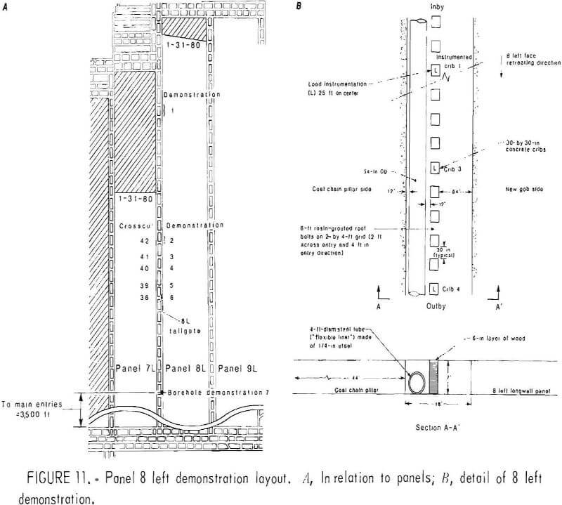
Two longwall faces, 7 left and 8 left, affected most of the seven separate demonstrations installed in the tailgate as shown in figure 11A. The planned layout of SFC cribs is shown in figure 11B. It consisted of a single row of spaced SFC cribs in approximately the center of the entry. On the chain pillar side of the single crib row, a 4-ft-diam steel tube was installed to maintain a return exhaust escapeway free from debris, which was the long-term application 2. The basic tailgate support during development was roof-bolted mat on 4-ft centers with a number of intersections and weaker areas having beams across them with post or crib support at the ends. Highly faulted areas had yielding arches and/or roof-bolted beams.
SFC crib support for the demonstrations was installed in the tailgate just after the adjacent 7 left longwall headgate end passed, about 1,500 ft outby the 8 left longwall face.
Demonstration 1
The first 145-ft long demonstration started about 900 ft from the starting crosscut of the 8 left longwall panel, under about 300 ft of cover. The adjacent 7 left panel was mining 1,600 ft ahead of the 8 left face. A 5-ft actual spacing was used for both SFC crib and
wood crib sections,. The demonstration section was a relatively good area where only the roof-bolted mats on 4-ft spacing along the entry were installed originally for support. All SFC cribs were of cross-stacked solid construction. Five cribs were 30 in by 30 in, and 25 were 30 in by 20 in. Two of each size crib were instrumented with hydraulic load cells. Each layer of a 30- by 30-in crib was made of three 30- by 10-in members. Thirty- by 20-in cribs consisted of alternating layers of two 30- by 10-in members and three 20- by 10-in members. All members were 3 in thick.
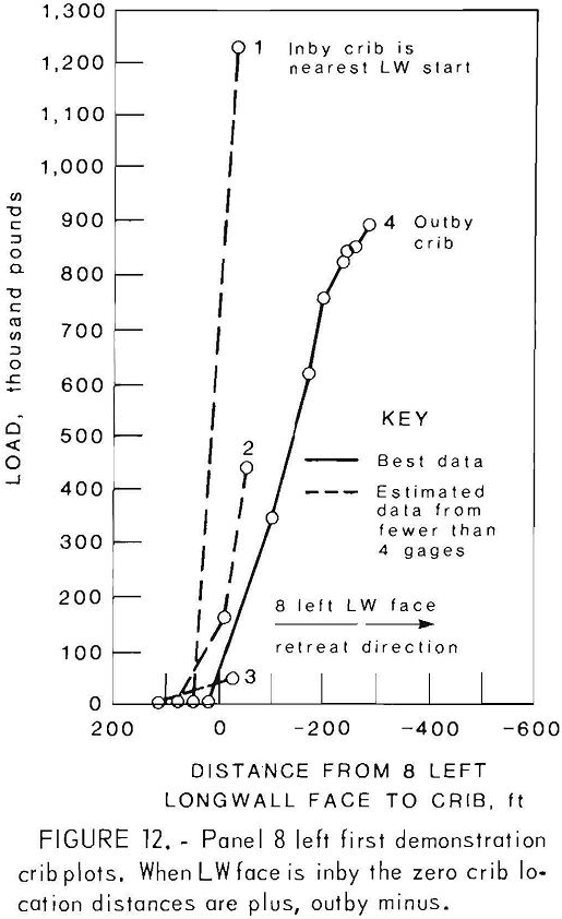
Figure 12 shows instrumentation results for crib load versus longwall face position. No loads were observed until after the 8 left panel face passed. Crib 1, the first inby 30- by 30-in SFC crib, had an estimated maximum load of 1,223,000 lb, or 1,360 psi.
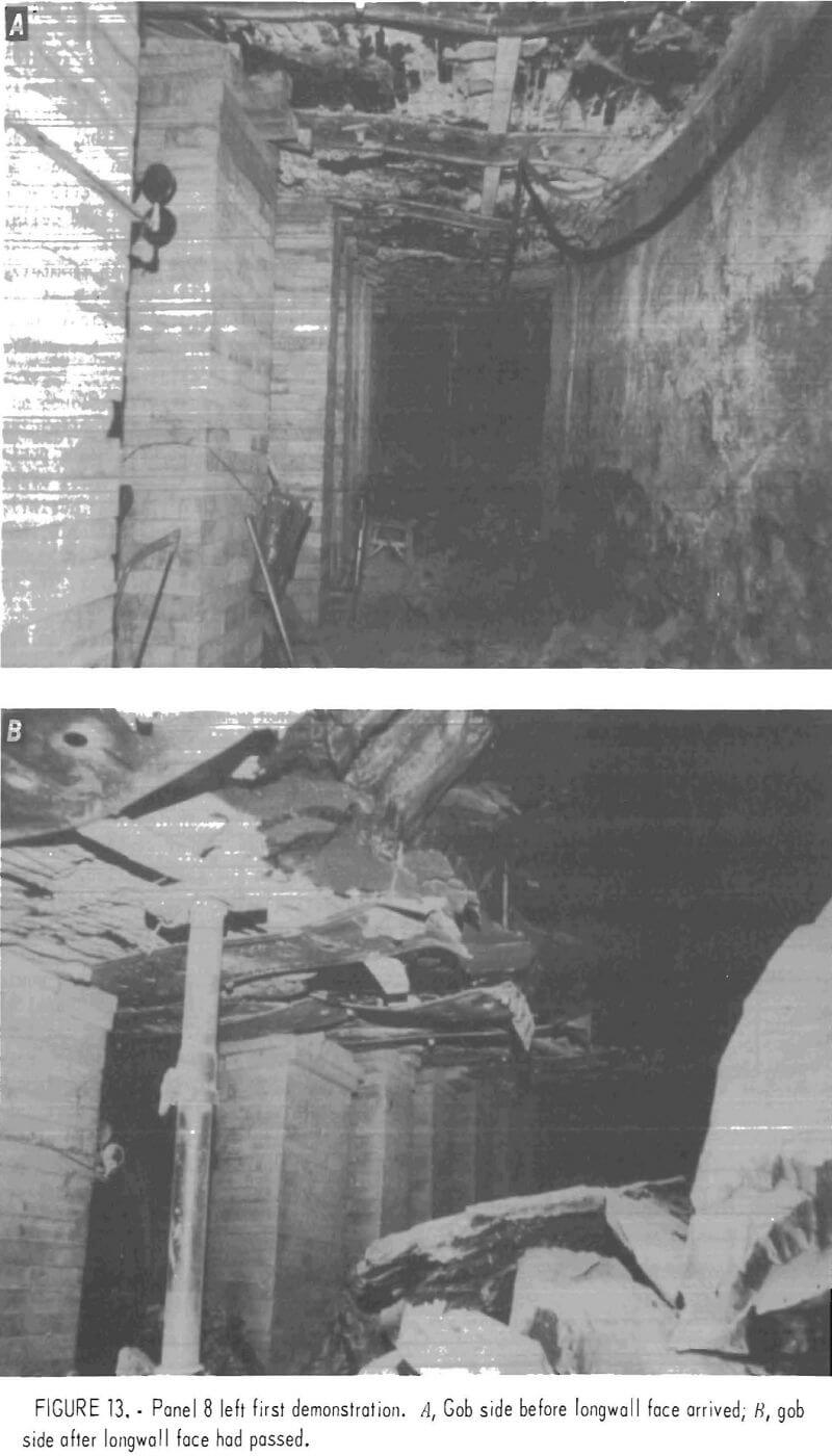
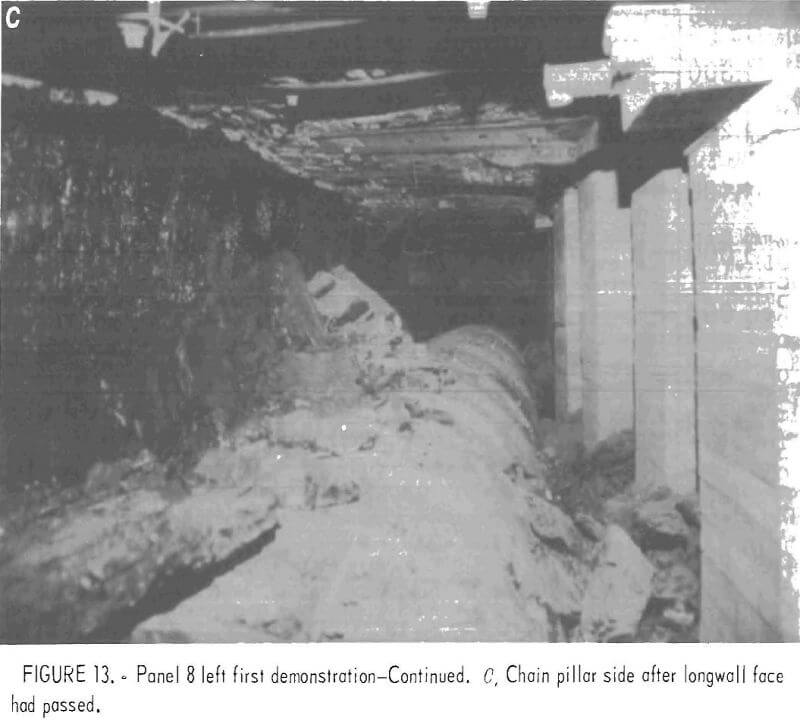
Cribs 2 and 3 provided limited information because the pressure gages were vandalized before peak loads were reached. Instrumentated crib 4 was 107 ft into the demonstration section at about two-thirds the distance from the starting end of the section. It was a 30- by 20-in crib. The maximum recorded load of 885,000 lb, or 1,480 psi, was increasing when the gages failed. It was believed loads were eventually much higher. When last observed in May 1980, the stiffer SFC cribs were maintaining the tailgate in a condition that would last the life of the 8 left panel as desired (application 2). There was less closure than with the wood crib sections and insignificant SFC crib damage (figs. 13A-C). Panel-end-support effects, shallow cover, and good ground conditions apparently delayed loading until after the 8 left face had passed. Later demonstrations showed loading from 900 ft prior to arrival of the 8 left face.
Demonstration 2
A second 115-ft-long demonstration was installed about 1,000 ft farther outby in the 8 left longwall tailgate in a faulted area with known poor ground conditions and about 600 ft of cover. The wood crib section between the first and second demonstrations was serving marginally with up to 2 ft of closure. Starting just inby the poor ground area, the original support included rock-bolt-supported steel beams and steel yielding-arch sets. Posts or wood cribs were added under most rock-bolt-supported beams, and wood cribs were sometimes placed between the steel yielding-arch sets on the new gob side of the normal row of wood crib in the center of the entry. In the worst area, the center was filled with a continuous row of wood cribs. The 115-ft SFC demonstration was placed in this worst area, ending at crosscut 42. All SFC cribs were solid square 30- by 30-in cribs located on 5-ft centers. Six of the SFC cribs were instrumented similar to the first demonstration.
Examination of figure 14 shows SFC crib loading started when the 8 left longwall face was over 900 ft away. This is a very different situation than that observed at the first demonstration in better ground. The entry was affected predominately by passing of the 7 left longwall face, and then by the approaching 8 left longwall face. Loads stabilized or decreased slightly after the 7 left longwall face passed. Loads increased when the 8 left longwall face was about 250 ft inby the demonstration section. Crib 2, near the start of the demonstration, had the lowest stabilized load. Crib 6, near the end of the demonstration, had the highest stabilized load. The stabilized load at crib 6 was
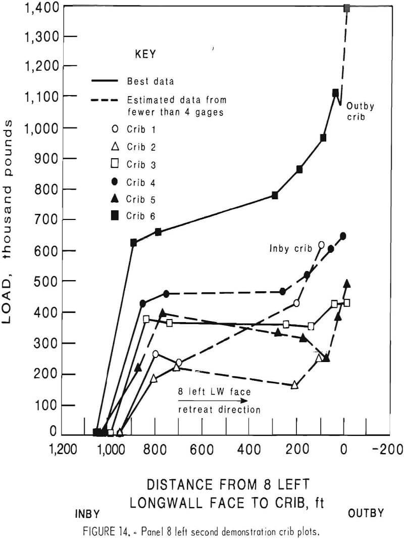
as much as 786,000 lb, 870 psi of bearing surface, or 157,000 lb/lin ft of entry. The average stabilizing load was about 355,000 lb per crib, 390 psi of bearing surface, or 71,000 lb/lin ft of entry.
Figure 14 shows the effect of the 8 left face approach was a definite increase in the loading rate beginning about 250 ft before the face arrived at the instrumentation. All instrumented crib loads were still rising when last read. Only crib 3, near the center of the demonstration, and crib 6, near the end, had all four gages functioning when last read. The highest estimated load observed, at crib 6, was 1,380,000 lb total, or 1,530 psi of bearing surface, or 276,000 lb/lin ft of entry. If the gages had remained accessible, no doubt higher loads would have been observed.
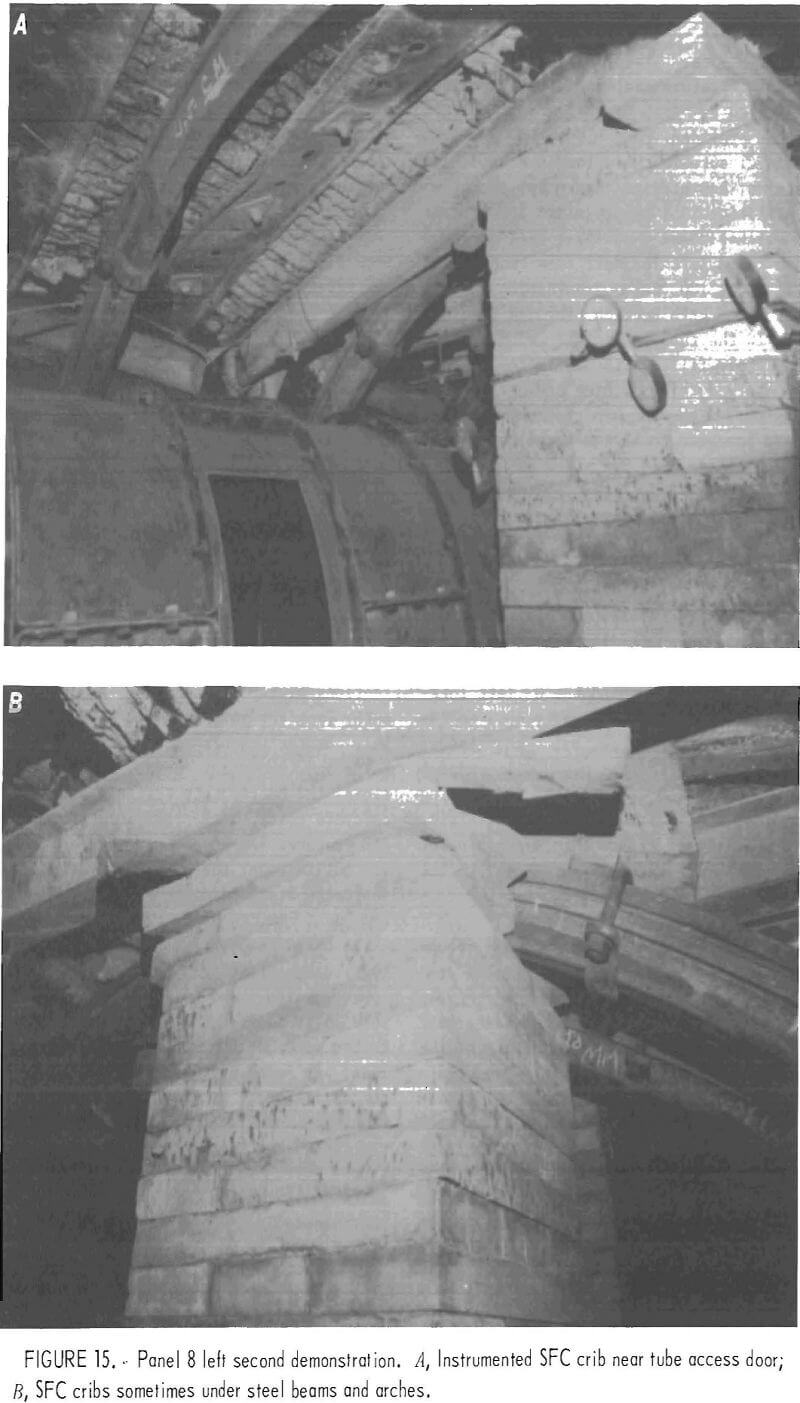
The second demonstration section showed less closure than inby and outby wood crib sections. The yielding arches were yielding before reaching the high load indicated by crib 6, indicating the SFC cribs provided the improved support. Rapid closure in the prior inby wood crib section had started damaging the steel ventilation tube by pressing steel beams and arches down upon it. This occurred when the 8 left longwall face had passed crib 1 by 100 ft. Examination of the inby wood crib section through openings left in the tube showed the wood section completely filled with debris to crib 1. As observed through three or four of the openings in the tube in the SFC section, there appeared to be two separate effects taking place: (1) The width of the entry opposite the SFC cribs remained intact, and the cribs had only minor cracks, and (2) between the SFC cribs, the roof was disintegrating and filling the space with small debris. Closure was on the verge of forcing roof-bolt and post-supported steel beams and yielding arches down into the top of the tube (fig. 15A). One concrete crib 20 ft behind the 8 left longwall face was cracked severly down to the instrumentation layer but was intact below. The crib had been built under a steel beam which was twisting and forcing the top half of the crib apart (fig. 15B). It was apparent that punching of the SFC cribs rather than damage to the cribs was allowing the closure.
The mine management was pleased to be able to mine through the poor-ground area at a rate faster than they had experienced in prior panels with the same geologic feature. Wood crib support of the tailgate area had previously produced a marginal support the mine was not satisfied with. The SFC cribs produced a satisfactory work condition in the tailgate until the second face passed by the rear of the chocks (application 1). Whether the SFC section stabilized later for application 2 with the tube still in a satisfactory condition, or not, was not observed. Because the tube was closing at the inby wood section, most return air later was rerouted to ahead of the face, exiting to the surface through a borehole between the two longwall faces. At last report, some air also continued to return out through the demonstration areas.
It is concluded that the layout used in the first two demonstrations would be sufficient for application 2 near the ends of longwall panels in good ground. In areas such as the second demonstration, a continuous wall might keep the entry tube open for the life of the panel. Because excess closure in this area was allowed by SFC crib roof punching, more bearing surface would be needed in this faulted area to reduce the closure for application 2, long-term tailgate support.
Demonstrations 3 Through 6
Four short demonstrations of similar configuration were installed at intersections 41, 40, 39, and 38, immediately outby from the second demonstration. In this better ground, needing only roof bolts and two steel beams at intersections, the appropriate testing sites for concrete cribs were the intersections. At crosscut 38, the instrumented crib was built under one of the roof-bolt-supported steel beams.
The third demonstration was 12 ft long, consisting of three SFC cribs. The fourth, fifth, and sixth demonstrations were 16 ft long, made of four cribs. All cribs were 30- by 30-in solid squares. There was one instrumented crib at each demonstration. At the third demonstration, the third crib was instrumented; at the fourth and fifth demonstrations, the second crib was instrumented; at the sixth demonstration, the fourth crib was instrumented.
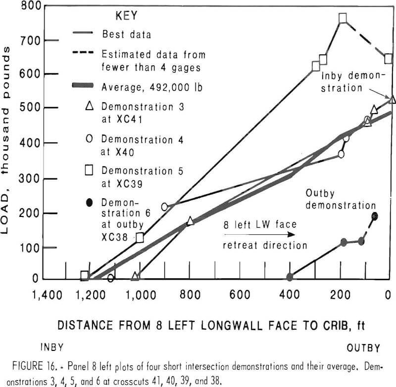
As shown in figure 16, loading started at 1,000 ft or more before the 8 left longwall face arrived at the instrumentation. The load is generally proportional to distance between the longwall face and the crib support in all four demonstrations, with an increasing load of about 430 lb/lin ft of retreat. This represents a 0.5-psi pressure increase per foot of retreat for each crib bearing surface. The average of the four intersections was 492,000 lb per crib when all were projected to zero distance. This was nearly equal to the crib load at the third demonstration, crosscut 41, which was actually measured at zero distance. The crosscut 41 load was 524,000 lb of total crib load, 580 psi of bearing surface, or 87,000 lb/lin ft of entry.
The mine management judged the four consecutive intersections of crosscuts to be more satisfactorily supported with the SFC cribs than the average intersection was supported with wood cribs. As the face approached crosscut 41, the wood-supported section between crosscut 42 and crosscut 41 was closing such that several steel beams in the area were on the top of the tube. A new row of wood cribs that was added on the gob side had already crushed and deformed ahead of the face, so that travel between the two rows of wood cribs was no longer possible. Travel to the face was only possible through the tube. The wood crib section between crosscut 42 and crosscut 41 offered marginal support at best. Superior results at the four short intersection demonstrations were similar to the superior results at demonstration 2.
Demonstrations 1 Through 6 Summary
Summary and observations of 8 left tailgate facts and conclusions from the first six demonstrations follow:
Application 1—Support of multiple- entry longwall tailgates until the rear of the second longwall face supports arrived:
The planned single-row-spaced SFC crib support system was superior technically to the similar prior wood crib support system. In good ground with 300 ft of cover, the SFC system could have been spaced out, or the cribs could have been of less bearing surface per crib, and the system would still have been equal to or better than wood cribs, with less closure. Increased spacing would have increased the economic attractiveness. In poor ground with 600 ft of cover, the technical superiority was more evident by general observation of each test section. No amount of wood cribs was satisfactory; the SFC system was.
The average load of the second demonstration cribs projected to zero distance as in the four short demonstrations was 694,000 lb, 770 psi, or 139,000 lb/lin ft of entry. The one-third higher load than in demonstrations 3 to 6 is attributed to the poorer ground at the second demonstration. At 200 ft from the longwall face, the average crib load for the four short demonstrations was 401,000 lb, compared to the second demonstration six- crib average of 444,000 lb.
Application 2—Long-term support of longwall tailgates, bleeders, returns, and return escapeways:
All mining industry personnel recognize this application as the most severe. The SFC crib support system showed promise for this application, but success was not proved because the test area did not remain accessible for observation owing to closing of wood system areas. In good ground with 300 ft of cover, the SFC system was maintaining the tailgate in a condition that would last the life of the 8 left panel; the wood crib system definitely was not, with closure up to 2 ft. Damage to the SFC cribs, and closure around them, was insignificant (figs. 13A-13C). In poor ground with 600 ft of cover, the slower closing SFC system was punching the floor and roof rather than the cribs disintegrating. At last observation, 50 to 100 ft behind the face, the punching SFC cribs had not yet destroyed the integrity of the roof opposite the cribs, although the roof supported with wood cribs between SFC crib locations was disintegrating into small debris. It was also clear that the wood crib system with steel beams and yielding arches was about to close the tube from above because ground movement was continuing at 130 ft behind the face. At least a continuous solid SFC crib wall with tube would have been needed in that location to provide enough bearing surface to reduct the punching, prevent disintegration of roof between individual cribs, and control the small-coal debris from the chain pillar. The SFC design stiffness and strength range were good for all applications except this one; a demonstration with more bearing surface is needed for application 2.
3. No justification for building stiffer and stronger SFC cribs was demonstrated. Cost would be increased with no safety improvement.
4. SFC crib punching in poor ground and 600 ft of cover was insignificant until after the second longwall face had passed the rear of the chocks. Then, punching accounted for the closure.
5. Disintegration of the SFC cribs was insignificant in poor ground and 600 ft of cover, where the tube was still intact at 100 ft behind the face when last observed.
6. It cannot be stated for certain, but damage effects were probably increased by the first face being within 1,600 ft of the second (or less than 8 months of mining distance).
7. Contrary to prior experience at another mine with deeper cover, short demonstrations exhibited very similar results to longer demonstrations. Poorer ground is believed to be the reason for these results. Demonstrations of 100 ft or longer are still preferred to get good load distribution data.
8. The method of individual crib construction was satisfactory.
9. The combined effect of (1) one- half the cover, (2) better ground conditions, and (3) possible panel-end support was to delay most of the loading of the SFC cribs at the first demonstration until 100 ft after longwall face arrival.
10. The combined effect of (1) double the cover of the first demonstration, (2) poor ground conditions from a known bad geologic feature, and (3) full-panel rock mass loading was to start loading at over 800 ft before the arrival of the second longwall face.
11. The second demonstration curve plot was the only evidence of a load stabilization between the arrival of the two longwall faces (fig. 14).
12. Maximum loads recorded or estimated were—
At demonstration 1
885,000 per 30- by 20-in crib 1,480 psi of bearing surface 177,000 lb/lin ft of entry
At demonstration 2
1,380,000 lb per 30- by 30-in crib 1,530 psi of bearing surface 276,000 lb/lin ft of entry
These loads were not the maximum at the locations. They were the loads at which gages started leaking, or were broken, or became inaccessible before being read again. It was believed that all demonstrations were subjected to loads less than the maximum strength of the SFC cribs because no observed cribs showed full-height cracks through the cribs.
13. The four short intersection demonstrations showed the onset of loading proportional to the distance from the longwall face until within 200 ft of the face.
Demonstration 7
A seventh demonstration of SFC cribs ins tailed in early 1981, supported the immediate area surrounding the bottom of a borehole for air return exhaust. This demonstration was not instrumented. The layout of the area is shown in figure 17. Thirty-inch-square solid SFC cribs were built as before. Farther from the borehole, standard open 36 -in-square wood cribs were used. The location has about 600 ft of stable cover. The purpose was to reinforce the area around the bottom of the borehole sufficiently to maintain it until the end of the panel life. If that purpose was not accomplished, another similar borehole would be drilled to finish the panel, or the return system would be routed through a finished 7 left panel.
Evaluation was based on visual observation only. Starting from the first lone crib, the other 10 SFC cribs were in a concentration of one crib per 1.9 lin ft of entry. SFC cribs were 6-½ ft high. The tube started again, 27 ft from the borehole. A double-wall airlock system
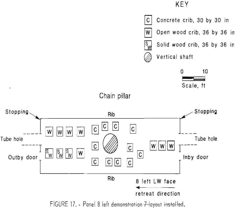
enabled air control in the manner desired, from inby and/or outby directions or none. The SFC cribs supported the base of the borehole satisfactorily until the face passed it, at which time the borehole was no longer accessible and was abandoned.
Experimental Sections at Other Mines
Several current and future demonstrations are scheduled at other mines. Because the results will not be complete for several years, only a short discussion of each is included here.
Bethlehem steel Co., Van No. 131 Mine
A demonstration was started early in 1981 at the Van No. 131 Mine of Bethlehem Steel Co., about 50 miles southeast of Charleston, W. Va., using design 3 SFC support members manufactured by The Burrell Construction & Supply Co. of New Kensington, Pa.
The first 166-ft-long demonstration at this mine is located in the 10 right longwall panel tailgate, a triple-entry (TE) layout between the 10 right longwall panel and 9 right longwall panel on the tailgate side of the 10 right longwall. Depth of cover is about 1,000 ft. The 9 right longwall face has finished mining coal, and the 10 right longwall face is now mining.
At the time of strain-gage installation on the SFC cribs, the 9 right longwall face was 70 ft inby the first pair of SFC cribs. Figure 18 shows the demonstration layout of SFC cribs.
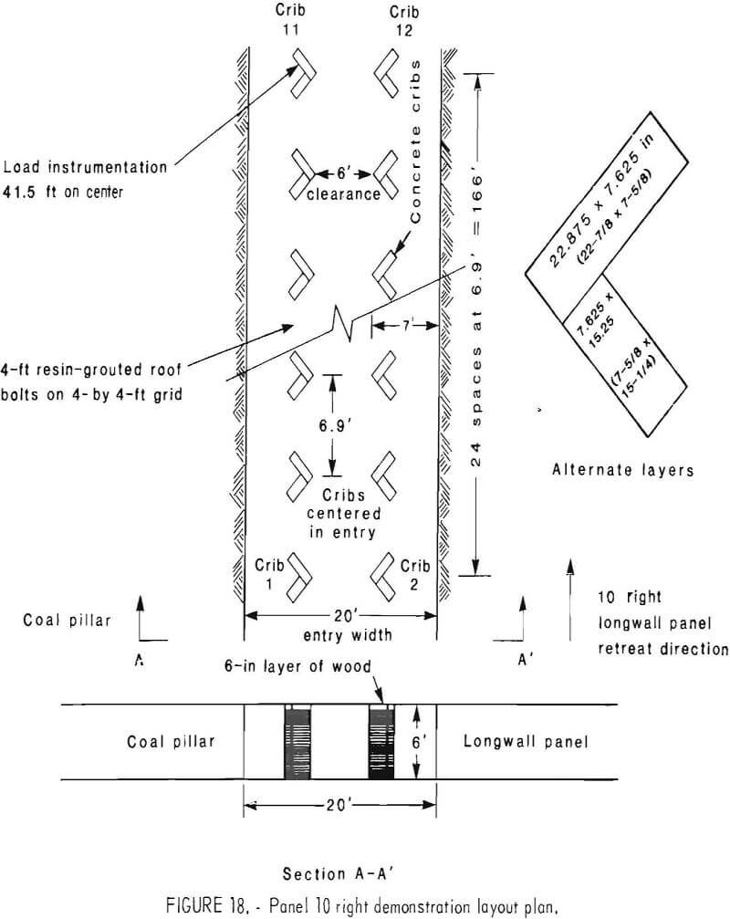
Twenty-five pairs of cribs on 6.9-ft centers along the entry, with 6 ft of clearance across the entry, made up the system. Cribs were built L-shaped with the point toward the center of the entry. The SFC cribs were placed between previously installed open wood cribs. The blocking at the top of the wood cribs was removed after the SFC cribs were finished and instrumented with strain gages.
The orientation of the cribs (fig. 18) was used to facilitate ventilation airflow. The bearing surface of 290.7 sq in per crib, using the L-shaped crib, was more appropriate for this application than larger solid square cribs would have provided on the same centers. It was decided mutually with the mine that a 6.9-ft spacing of the wood cribs should not be exceeded. The 84 sq in of bearing surface per linear foot of entry would be a load capacity of 252,000 lb/lin ft of entry calculated at 3,000 psi. Each layer consisted of two blocks, one 22.875 in and one 15.25 in long. Position of blocks was alternated so that each joint was overlapped by the layers above and below, tending to lock the whole crib together.
Cost of individual blocks at the factory, as of mid-1983, was $2.29 for the 22.875-in-long blocks and $1.53 for the 15.25-in-long blocks. Shipping from the Burrell Construction & Supply Co., New Kensington, Pa. , factory to the mine site cost about $0.50 per block.
The SFC cribs were instrumented with two pairs of vertical 1-in strain gages per crib, one pair epoxied to each of two individual blocks in a middle layer. The inby block was labeled set A, and the outby block was labeled set B. Five of the 25 SFC crib pairs were instrumented, including cribs 1, 2, 11, 12, 23, 24, 35, 36, 49, and 50. Gage 35A was a bad installation and would not function. Base readings were taken by manual electronic microstrain indicator. The first cribs to be passed by the current 9 right long- wall face were the pair numbered 1 and 2. The odd-numbered row of cribs was nearest the 9 right longwall panel; the even-numbered row was nearest the 10 right longwall panel coal rib, which will be mined in the future.
All SFC cribs were constructed and wedged prior to instrumentation. When the first data set had been read, the wedging on the alternating wood cribs was removed and a second data set was obtained. This procedure showed increased load when the wedging of the wood crib system was removed. With time, reduced load was observed. Apparently, this effect was caused by (1) cantilevered action across the two chain pillar rows as a fulcrum for the closing longwall area on the opposite side of the chain pillars, (2) drying shrinkage of wood at the top of the. SFC cribs, or (3) water inflow as the longwall approached, which weakened the floor structure.
United States Steel Corp., Gary No. 9 Mine
The Gary No. 9 Mine, near Bluefield, W. Va. , started a 500-ft demonstration of the SFC crib support system in 1981 using design 3 members provided by the Bureau. Members were bought from the eastern manufacturer at $2.29 per member and transported by truck for about $0.50 per member. Square open cribs were constructed. The shape allowed arrangment of SFC crib-bearing surface in a pattern similar to the mine’s wood cribs at less cost than that of a solid SFC crib.
The company was responsible for all design, installation, and instrumentation. Five hundred feet of a longwall tailgate was supported with a single row of cribs spaced on 6-ft centers along the tailgate and 8 to 9 ft from the chain pillar to the center of the row. The seam height is 48 in, which makes a reduced closure more important than in thicker seams.
Results of this evaluation indicated that significant safety and economic advantages might be possible for SFC concrete cribs compared to wood cribbing in this application.
Texasgulf Co., Trona Mine, Rock Springs Area of Wyoming
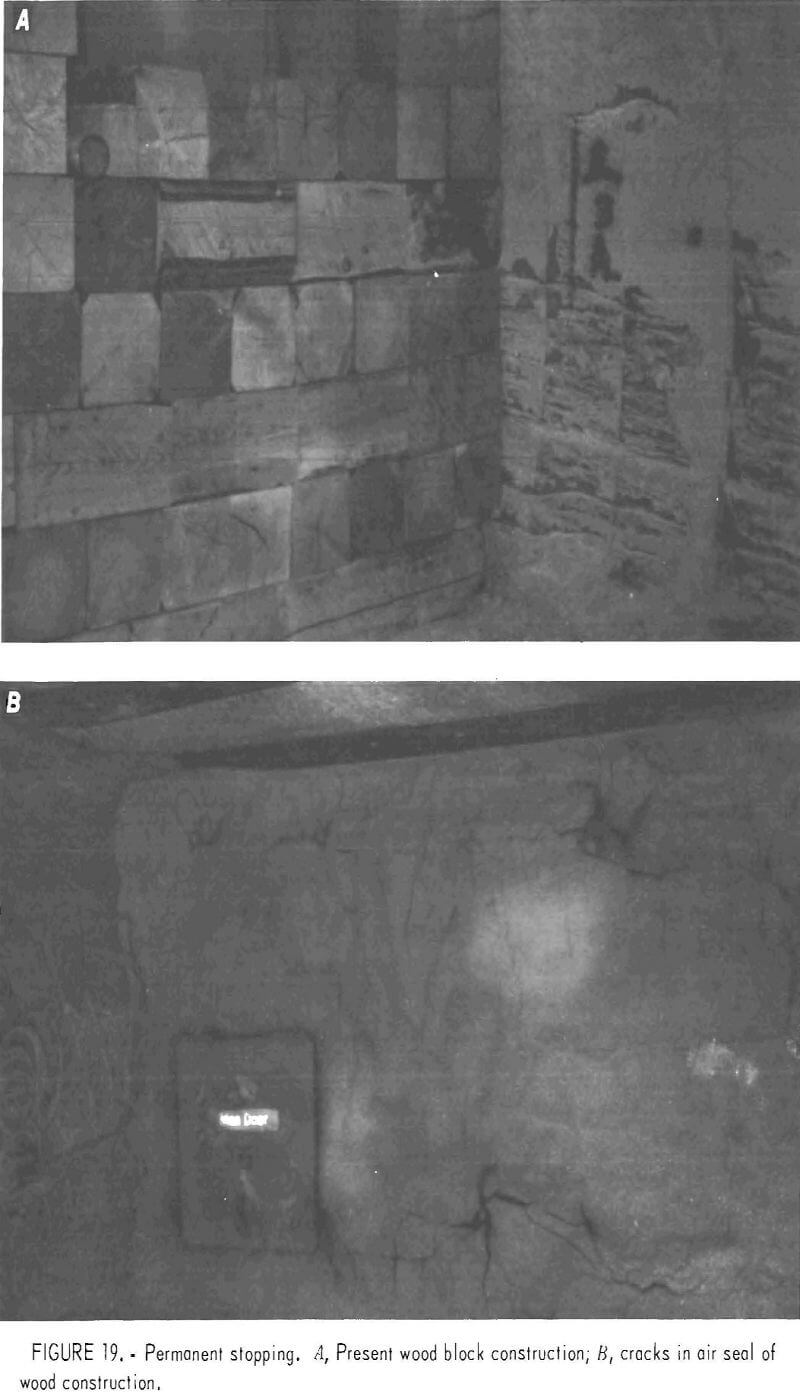
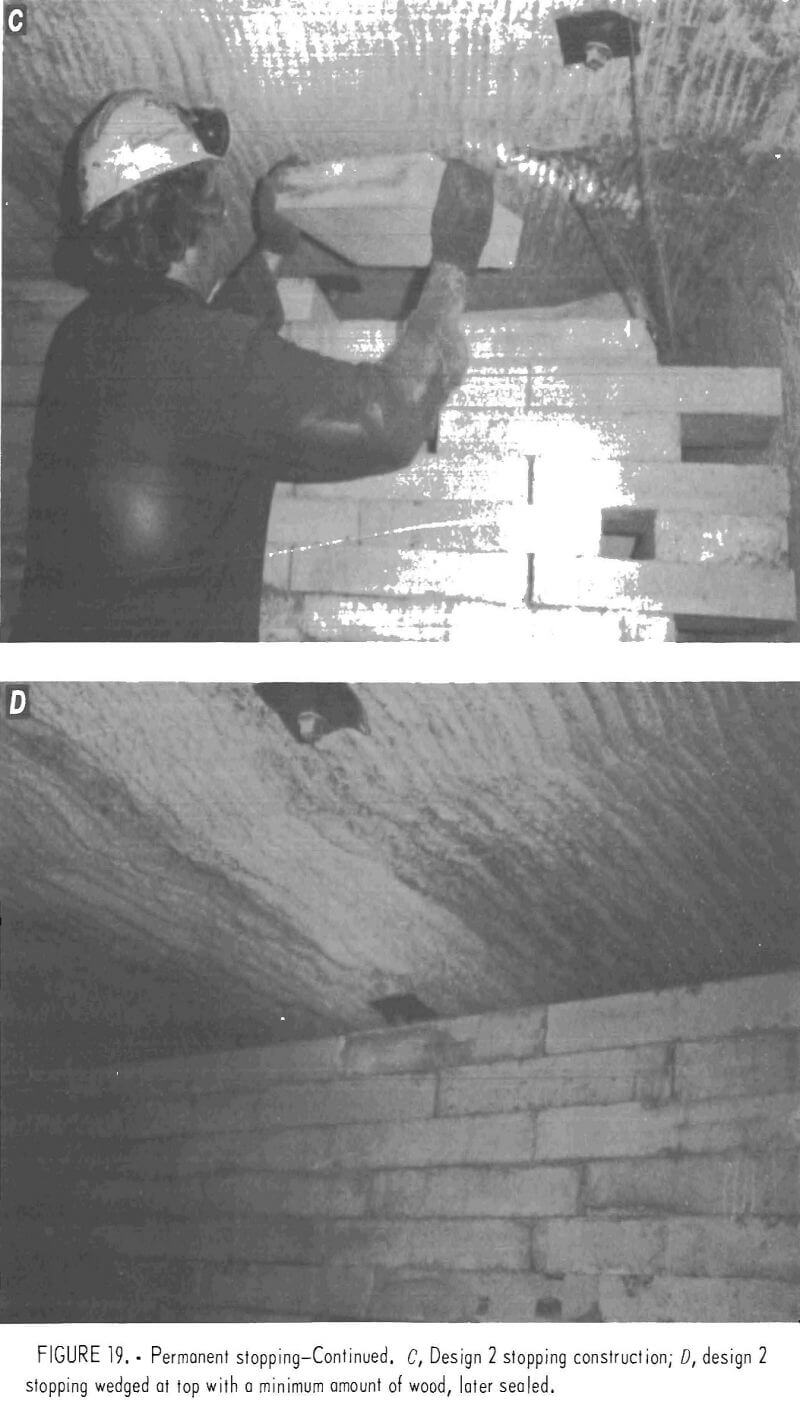
In 1980, the Texasgulf Co. installed a stopping made of SFC design 2 members provided by the Bureau. The objective was to find a stopping material that required less maintenance. A stiffer material allowing less closure and more easily sealed than the wood would fill this requirement. The SFC members should be more compatible with the gunite sealant placed on the surface of the stopping.
Because installation was in an area of the mine with little roof loading, proof of favorable results will require several years at least. See figures 19A to 19D for construction of the present wood stoppings, cracking of the seal on the wood stoppings, and construction of the design 2 SFC member stopping.
Snowmass Coal Co., Thompson Creek No. 1 Mine
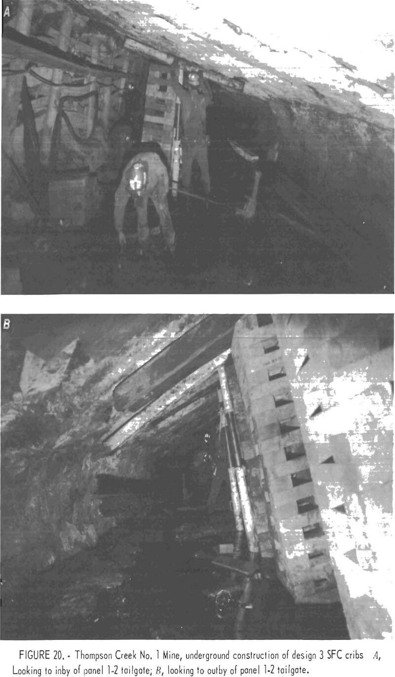
Installation of 5,130 ft of design 3 SFC cribs began in 1981 at the property, which is 12 miles southwest of Carbondale, Colo. The A seam is about 7.5 ft thick, with a pitch between 27° and 34°. The demonstration location in the future tailgate of panel 1-2 had a pitch of about 27°. About 2,200 ft of SFC cribs were installed by early 1982. The planned layout resembled that shown in figure 11, but without the tube. Figures 20A and 20B show similar underground installations. Part of the wood wedging and blocking is salvaged track ties.
The cribs started at the beginning of the panel 1-1 longwall face. Open-square cribs are used except for instrumented solid-square cribs. All cribs are placed in a single row on about 6-ft centers, and 6 ft from the chain pillar side of the 16-ft-wide entry.
The first instrumented solid-square crib was installed at mine marker 535 under about 750 ft of cover. Panel 1-1 longwall face was approaching the instrumented crib from 235 ft away. The high-load gages showed nothing as panel 1-1 longwall face passed, but adjacent Department of Energy (DOE) low-load gages recorded 20 psi at this location. Six months later, 50 psi was recorded at about 1,200 ft of cover. More high-load gages will be installed near the 1,750—ft maximum cover for the tailgate.
Chain pillars in this double-entry tailgate are about 200 ft long and 80 ft wide. The 1,750-ft cover area is downdip from a previously mined area that may cause a large difference in SFC crib performance in this entry by the time it has been used as a tailgate. This one- row open-crib installation will be monitored ahead of the panel 1-2 longwall face in the future, and cribs will be added as needed. At the start of panel 1-2, with about 500 ft of cover, additional cribs probably will not be needed. At the 1,750 ft of cover, it is likely additional cribs will be needed.
Design Guidelines Support, Cost, and Installation
General guideline information includes the following:
- Mine personnel at individual mines will have the best overall knowledge of factors involved in crib layout design and the relative importance to their mine operation.
- Make test sections of the the SFC crib support system 100 or more ft long, and consider the middle portion representative of results rather than the 20-ft ends. Doubling the crib concentration at the ends is another approach to minimizing end effects. Experience shows that results on the ends, due to transition from the less-stiff medium of wood cribs to the more-stiff SFC cribs, sometimes are drastically different from results on the middle portion of a test section.
- Be sure to include about 1 in of wood wedging and blocking per foot of seam height, preferably at the top where disintegration effects usually appear first. The wood makes a composite crib with loading characteristics similar to those of chain pillars of coal.
- Solid crib designs make better use of all the SFC material because the center portion tends to be confined by the perimeter portion, thereby increasing the center portion strength. Consequently, a solid crib to open crib ratio of strength is 225 pct or more for a 150-pct cost ratio. In low-load applications requiring less concentrated support for strength, and where roof is inclined to break up into small pieces, open cribs may more uniformly support the total area satisfactorily than an equal amount of material in solid cribs.
- Cost of members at the mine varies widely because of different transportation distances, which are an important consideration.
Support Criteria
These design guidelines are not guaranteed for all situations, but should be used as preliminary or general guidelines only. It is noted that the strength of the support systems must be compatible with the bearing capacity of the roof and floor strata. Minimum support required in any entry during the development phase of mining is the first consideration. Detailed information is given in the following section.
Development Phase Support of All Entries
Support strength required during the entry development phase is low compared with that needed later in a longwall entry. Development support strength gives a common basis for comparison with entries that are used for other purposes. A simple equation to approximate the required support is—
S = C/L………………………………………………………………………………………(1)
where S = center-to-center spacing, in linear feet per support,
C = useful support design capacity, including safety factor desired, in pounds per support,
and L = dead load, in pounds per linear foot of entry.
The following factors should be considered in applying the equation:
- Evaluation information for L = dead load includes depth of cover, geological characteristics, pressure arch height, immediate roof height, roof-bolted height, and known load variations in the area to be supported.
- Bearing load on supports that is less than the usual bearing strength of roof or floor should be successful. In most cases, SFC bearing strength capacity will be 3,000 psi or more. Bearing surface qualities of immediate roof and floor can be determined in part by results of bearing tests and by past experience with less stiff wood support and more stiff, rigid-steel-set support.
- The height of the SFC portion of the crib should exceed the minimum desired roof-to-floor clearance. In low coal, for example, this may be critical. Less top wood might reduce closure long enough to pass a critical time stage in the mining operation. A minimum of 1 in of wood per foot of seam height is needed, however. The wood is needed to make the crib converge at about the same rate as the nearby coal pillars so the crib will work with the coal pillars.
- An increase in concentration of SFC support may be needed at intersections or in faulted areas. Some closure has usually taken place before cribs can be installed, so variations observed with temporary and permanent support indicate variations in SFC support needed. Past observation of roof or floor breaking into small pieces, or of minimum support required to maintain a certain roof or floor span intact, indicates the best crib spacing. Other indicators are successful roof-bolt plans and occurrence of roof falls in similar ground.
If one considers a support system in a 20-ft-wide entry, with a safety factor of 2, 6-ft roof bolts used for support, a 6-ft assumed dead load height, and the strength of each roof bolt = 30,000 lb, application of equation 1 is as follows:
S = C/L,
where S = center-to-center spacing, in linear feet per support,
C = 30,000-lb strength, divided by safety factor of 2,
= 15,000 lb per roof-bolt support for capacity,
L = 144-pcf density of roof, times 20 ft of entry width, times 6 ft of roof-bolted height as the dead-load height,
= 17,280 lb/lin ft of entry for dead load,
and S = 15,000 divided by 17,280 = 0.87 lin ft per roof bolt, or
= 5 ft per 6-roof-bolt row of support, minimum amount of support required, or maximum spacing for these roof bolts.
If one considers the previous roof-bolted support example, or a roof capable of supporting up to a 20-ft-wide span, and wishes to add visible support of open wood cribs using 10- by 10-in members with four corners of 100 sq in = 400 sq in of useful bearing area, 500-psi ultimate wood strength, application of equation 1 is —
S = C/L,
where S = center-to-center spacing, in linear feet per support,
C = 500-psi unit area strength, times useful area of 400 sq in, divided by safety factor of 2,
= 100,000 lb per support for capacity,
L = 17,280 lb/lin ft of entry for dead load (the same as in the previous example),
and S = 100,000 divided by 17,280, or
= 6 lin ft per support in one row, or
= 12 lin ft per paired-row of open crib installations, minimum support required, or maximum spacing for this strength of open wood crib.
If one considers an SFC support system layout of one open crib row in a 20-ft-wide entry, with 233 sq in of useful bearing surface, a safety factor of 2, and a previously roof-bolted roof or roof capable of supporting a 20-ft-wide span, the following is an example of the use of equation 1:
S = C/L
where S = center-to-center spacing, in linear feet per support,
C = 3,000-psi SFC strength, times 233 sq in of useful area, divided by safety factor of 2,
= 349,500 lb per support for capacity,
L = 17,280 lb/lin ft of entry for dead load (the same as in the previous examples),
and S = 349,500 divided by 17,280, or
= 20 lin ft per support in a one-row open-crib SFC installation, minimum amount of support required, or maximum spacing for the development phase.
How does use of the preceding simple equation relate to the real world? The equation appears reasonable as indicated by the following:
- Quality of roof requiring roof bolts—the equation agrees with the standard of 5 lin ft per roof-bolt row as maximum spacing.
- Quality of roof requiring addition of open wood cribs—most mines space open wood cribs on centers less than 12 lin ft per pair.
- Roof previously roof bolted or equivalent quality—lengthwise center-to- center maximum spacing answer for open SFC cribs agrees with the maximum width span of 20 ft allowed for roof-bolted entries.
Longwall Extraction Phase Tailgate Support
In many cases, closing forces in a multiple-entry tailgate exceed the ultimate strength of the permanent support system, allowing the tailgate to cave soon after additional temporary support is removed. If previous examples are considered under longwall tailgate conditions, several factors in the equation change. A safety factor of 1 is more appropriate, a dead-load height of 24 ft is more realistic, and use of roof bolts only for support will not be considered.
In the previous example concerning open wood cribs, the equation results become as follows:
S = C/L,
where S = center-to-center spacing, in linear feet per support,
C = 500-psi unit area strength, times 400 sq in useful area, divided by safety factor of 1,
= 200,000 lb per support at failure capacity,
L = 144-pcf density of roof, times 24-ft dead-load height, times 20-ft width of entry,
= 69,120 lb/lin ft of entry for dead load,
and S = 200,000 divided by 69,120, or
= 3 lin ft per support, or one continuous row of 36-in open wood cribs,
= 6 lin ft per paired row of open wood cribs, minimum amount of support required, or maximum spacing, for open wood cribs of 10- by 10-in members.
Similarly, in the previous example of open SFC cribs, the results for a longwall tailgate change to become—
S = C/L,
where S = center-to-center spacing, in linear feet per support,
C = 3,000-psi SFC strength, times 233 sq in of useful area, divided by safety factor of 1,
= 699,000 lb per support at minimum failure capacity,
L = 144-pcf density of roof, times 20 ft of entry width, times 24- dead-load height, or
= 69,120 lb/lin ft of entry, tailgate dead load,
and S = 699,000 divided by 69,120, or
= 10 lin ft per support using open SFC cribs in one center row, maximum spacing for the very best of tailgate conditions
However, with roof disintegration more likely at the average longwall tailgate with only favorable conditions, a maximum unsupported span of 5 ft between cribs is advisable. The result must therefore be—
S = 7 lin ft per open-crib SFC support, minimum amount of support required, or maximum center-to-center spacing for average long-wall tailgates until the rear of the longwall face supports has arrived.
Under favorable conditions of floor and roof, underground experience confirmed the preceding as usually valid for a 1,000-ft or less depth of cover.
Under poor conditions, or more than 1,000 ft of cover, solid SFC crib at 5 ft per support in one center row should be considered a maximum spacing for longwall tailgate use.
Support of Tailgate to End of Panel Life
If this application 2 use becomes necessary at a mine, rock mechanics experts should be consulted for an interpretation best suited to that individual mine. However, a rough approximation of the support spacing may be obtained with equation 1.
Chain pillars are usually designed to crush out after the rear of the longwall face support has passed, as was discussed in the previous section. Such design makes this use extreme. Because wood-sections always became inaccessible for travel to the SFC test sections, judgment concerning this application is very subjective.
Four approximations are provided using equation 1 in the same way as in the previous section about longwall tailgates, but depth of cover is now used for the dead-load height. Solid-square SFC cribs with 523 sq in of useful support area also are presumed necessary.
Solid SFC crib requirement per 1,000 ft of cover depth is—
S = C/L,
where S = center-to-center spacing of solid SFC cribs, in linear feet per support,
C = 3,000-psi SFC strength, times 523 sq in of useful area, divided by safety factor of 1,
= 1,569,000 lb per support for capacity,
L = 144-pcf density of roof, times 20 ft of entry width, times 1,000-ft depth of cover dead-load height,
= 2,880,000 lb/lin ft of entry for dead load,
and S = 0-54 lin ft per support in one row (not possible) or
= 2 lin ft per four-row support of solid SFC, or four continuous walls.
Other solid SFC crib requirements are in proportion to the cover depth, so that similarly—
S = 2 lin ft per three-row support for a 750-ft cover depth,
S = 2 lin ft per two-row support for a 500-ft cover depth,
and S = 2 lin ft per one-row support for a 250-ft cover depth.
Also, the bearing load on the crib should not exceed 3,000 psi or the roof and floor bearing strength, whichever is smaller. A conservative view is that application 2 should be restricted to multiple-entry tailgates that have non-crushing chain pillars. If continuous-wall solid SFC cribs are considered a prefabricated pack wall, pack wall design is one option for use by rock mechanics experts.
Cost
Approximate factory cost for a 6-ft-high SFC crib, when blocks or members cost $2.29 each, is shown in table 2. At least a 100-ft experimental test section is recommended. Six SFC crib supports for 100 ft meet the maximum 20-ft spacing guideline at minimum caste. Costs for such a case are—
Six open cribs $87.02 = $522 for 100-ft section, industry minimum.
Six solid cribs $130.53 = $783 for 100-ft section, industry minimum.
However, most applications to date anticipate longwall tailgate use. A minimum for one SFC row on recommended 7-ft spacing requires—
15 open cribs $87.02 = $1,305 for 100-ft section, industry minimum.
15 solid cribs $130.53 = $1,958 for 100-ft section, industry minimum.
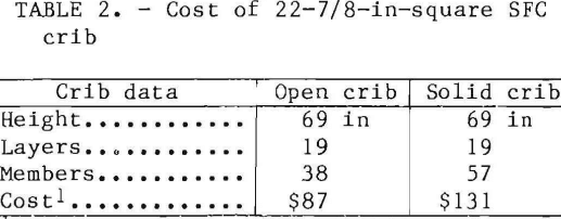
Table 3 presents a cost comparison with wood cribs on a one-to-one replacement, based on a wood member cost of $10 for a 36-in-long 10- by 10-in timber, or $0.40/bd ft, and factory-priced SFC crib members.
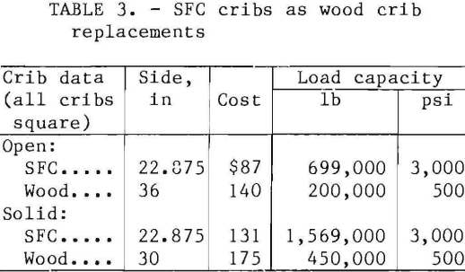
The load ratio of 3.5 to 1 means that if other factors do not rule against it, the commercial design 3 SFC cribs can be spaced up to 3.5 times as far apart for equal strength when using the crib sizes shown in table 3.
A calculation similar to one in RI 84125 was made based upon equal support strength of wood and SFC crib systems, but using 3,000 psi for SFC crib strength. It included most costs and showed a cost ratio of 2.2 to 1 favoring SFC support.
Added to the basic $2.29 per block cost at the factory, truck transportation costs are about $0.50 to most mines.
Installation Procedure
SFC cribs of various configurations have a number of installation procedures in common. Installed either vertically or inclined, the basic procedure is—
- One inch of wood wedging and blocking per foot of seam height is required over the entire bearing surface of the crib to prevent overloading and point loading of the crib. This results in a “composite crib” in which the cushion of wood wedges and blocking crushes first at lower loads and fits the bearing area to the roof shape. The combined wood and SFC portions have a spring quality that provides flexibility during sudden loads such as bounces and approximately matches the stiffness of the surrounding coal pillars. This allows the cribs to share the loads with the pillars rather than taking all the load and failing prematurely.
- It is advisable to install cribs as much as 1,000 ft ahead of the approaching LW face under poor roof or floor conditions. Under these geologic conditions, from 800 to 200 ft ahead of the LW face, loading was proportional to the distance from the LW face.
- Clean the floor of all loose muck to a plane matching that of the crib to be built.
- For safety reasons, use a configuration that has members of one layer crosswise to layers above and below. This tends to hold the crib together by friction, so a portion is less likely to tip over and injure the builder.
- For maximum crib efficiency, make layers match so sides are in a straight line. Members with less than the full area used owing to poor construction will have higher than average load per square inch and fail sooner than necessary.
Industry Acceptance
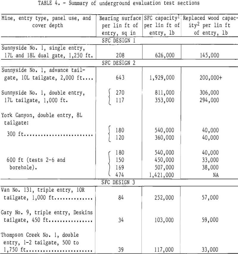
Mine acceptance is indicated by the seven mines in this report establishing experimental sections and use of SFC cribs by other mines on a production basis. Two mines contemplate full-panel lengths of an open-crib SFC support system with a 22-7/8-in-sq shape if crib underground evaluation Is encouraging. Industry experience indicates that for less or equal cost, compared with open wood cribs, an equally safe workplace can be maintained for a longer time.
Table 4 summarizes industry experience.
Commercial Design 3 SFC Members
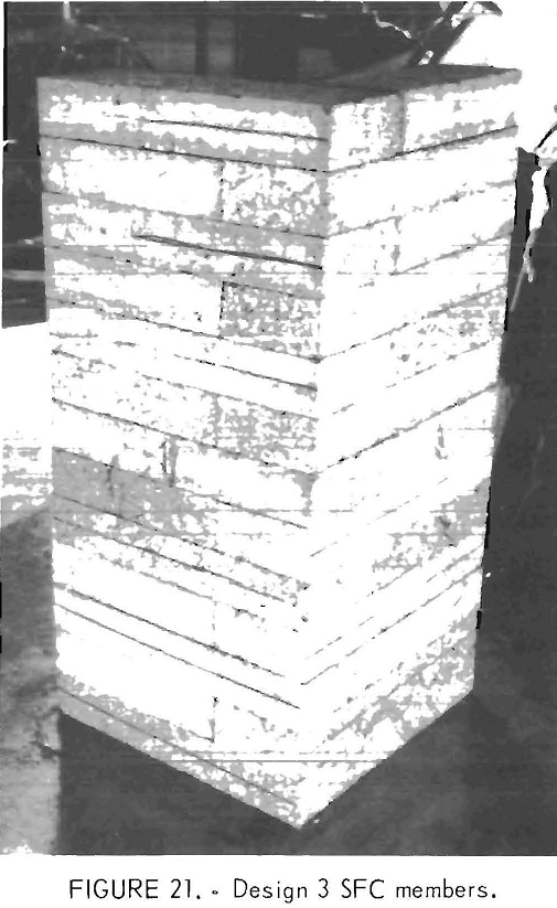
Design 3 is a commercial design mass produced by Burrell Construction & Supply Co., New Kensignton, Pa. The two standard-size blocks made are 22.875 in by 7.625 in by 3.625 in, and 15.250 in by 7.625 in by 3.625 in. Crib strength is 3,000 psi or more. Standard concrete block production machines are used, with proprietary method modifications. Figure 21 shows members produced by the process.
To date, four local producers are franchised, at Salt Lake City, Utah, Tiltonville, Ohio, Briston, Tenn., and Kingsport, Tenn.
Conclusions
Conclusions from RI 8412 (1980) are still valid, based on later work discussed in this report. As a review, conclusions of RI 8412 were—
- It appears technically and economically feasible to use steel-fiber-reinforced concrete cribbing as a substitute for wood cribbing for mine roof support.
- Certain steel-fiber-reinforced concrete supports offer superior stiffness and strength in compression compared with wood supports, yet they avoid the brittle or catastrophic compressive failure mode of plain concrete.
- Steel-fiber-reinforced concrete supports may offer significant cost savings compared with wood supports.
- Based on fiber quantity, the bent-end type of steel-reinforcing fiber was the most effective in increasing the after-failure toughness of concretes
- The configuration and dimensions of full-scale cribs, made of steel-fiber reinforced concrete, affect their ultimate compressive strength and after failure toughness. The supports with solid, smaller cross sections and fewer joints tended to have the highest ultimate strength per unit area and the greatest toughness after failure.
Application 1 conclusions for SFC crib support of multiple-entry longwall tailgates, until the rear of the second longwall face supports has arrived at each crib are as follows:
- Slower roof-to-floor convergence around the SFC cribs permits safer completion of work in a shorter time.
- SFC cribs are technically superior to wood cribs. The strength of SFC cribs is more than adequate for this application. Usually, SFC cribs are loaded beyond their ultimate strength by the time the rear of the longwall face support has arrived. However, the post-ultimate strength, or toughness, is sufficient to meet the application requirements in a manner superior to wood.
- The start of loading on the SFC cribs occurred as far as 800 ft from the retreating longwall face, but was typically 200 ft. Rapidly increasing loads were observed at 200 ft or less before face arrival.
- Near the starting end of a longwall panel, crib loading did not start until after the face had passed.
- When multiple rows of SFC cribs are used in a longwall tailgate, initial loading of the crib rows is proportional to the distance from the intact chain pillar.
Application 2 conclusions for SFC crib long-term support of longwall tailgates, bleeders, returns, and escapeways (maintaining a tailgate behind the face until panel completion is a specific example) are as follows:
- No test sections remained accessible for conclusive documentation. Subjective judgments are therefore necessary. In a multiple-entry tailgate, at least a continuous solid crib wall would be needed to provide enough bearing surface to reduce punching, prevent disintegration of roof between cribs, and prevent excessive disintegration of some cribs prior to panel completion.
- Except in the most favorable circumstances, a tube or liner would also be needed to control small coal debris from the remaining chain pillar. When the tailgate is kept open for an air return, travel through such a tailgate for inspection might require a second wall on the chain pillar side. Without a tube or liner, perhaps continuous open-crib wall construction would be sufficient for the second wall to contain sloughed chain pillar coal.
- With stiffness similar to that of the surrounding rock mass, SFC cribs should be ideal for long-term stability in other entries such as bleeders, returns, and escapeways.
- From effects observed in under-ground instrumented cribs, it was found that, generally, load estimation can be made visually. Crushing of the wood blocking at the top of the crib to about half the original thickness, without concrete crushing, indicates about a 1,000- psi loading. Crushing of one or more layers, or diagonal cracks through the SFC crib, means ultimate strength of the crib as a unit has been reached. Distortion of crib shape indicates the post-ultimate-strength phase has been reached.
Application 3 conclusions for SFC crib support of an advancing tailgate with a pair of continuous SFC crib walls were documented with an incomplete test section. From previous longwall tailgate experience, maximum loads were not observed before the panel was stopped for reasons not pertaining to the type of support. Partial results observed were encouraging.
Favorable economics, performance, and acceptance by the mining industry are indicated.
