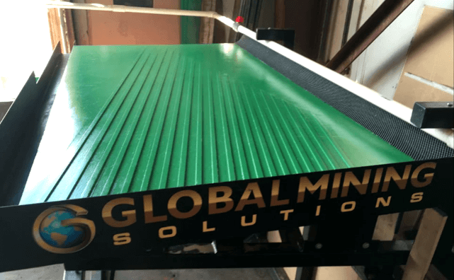
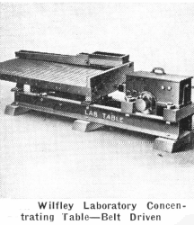
For running laboratory tests on a small scale, a laboratory size Wilfley Concentrating Table is an indispensable unit. The action of the Wilfley Laboratory Concentrating Table duplicates that of the commercial units and laboratory results can be accurately reproduced in commercial operation. This laboratory table is also used extensively as a pilot table to indicate the efficiency of a flotation circuit.
This table consists of a single or double deck mounted on a steel channel under structure, with enclosed self-oiling head motion, improved draw bar, and a positive tilting device. For small scale pilot plant operation the 50″x 24″ deck is recommended, and for batch test work the 40″x 18″ with two decks (one for sands, the other for slimes) is most desirable.
For use in batch operations, a set of special product pans has been designed for catching the middlings, concentrates, and tailings. These contain small supplementary pans which can be shifted for cutting samples.
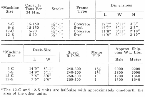
 |
|
|
|
|
The Wilfley Concentrating Table is a mechanically operated, longitudinally reciprocating table consisting of a self-oiling, enclosed type head motion; a deck having a plane surface partly riffled; and a sturdy under-structure with a tilting device. It separates materials into bands and handles the coarsest sands with excellent results. Thousands of these tables are in use the world over and their efficiency, long life, and low upkeep are features recognized by the entire mining industry.
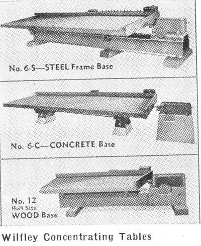
The upper unit shown in the accompanying illustration is equipped with a steel frame. This is the latest, improved type, single deck Wilfley Concentrating Table. It has oil-immersed rocker bearings which carry the deck on a steel frame that is bolted to cast iron separators. This insures maximum rigidity and alignment of the mechanical parts. Operation is by an enclosed, self-oiling, head motion and the tilting device consists of a tilting cradle and rods which work through miter gears and assure the operator of positive, non-slip adjustment when once set.

The second unit in the illustration shows the same table with the exception that this unit is designed for operation on a concrete under-structure consisting of three concrete piers. This is the ideal table for isolated plants as the shipping weight is approximately 30% less than the steel frame type. It can be used wherever concrete piers can be erected. This design assures maximum rigidity which insures correct maintenance of mechanical alignment.
The lower concentrating table in the illustration is of similar construction but is built with a considerably reduced deck area, having approximately one-fourth the area of the other units. This table is ideal for pilot plant work and can be made with either a steel or concrete frame.
Capacity of any concentrating table is increased as the size of the feed is increased. The better the sizing or classification of the table feed, the better the separation:
- the larger the tonnage that can be handled,
- the higher the grade of concentrates that can be produced, and
- the higher are possible recoveries.
Various types of Wilfley Concentrating Tables are available for use on many types of treatment problems. For some of the many applications of these units, further details on their construction, and capacities under various operating conditions, write to any Equipment Company office and additional data will be gladly furnished.
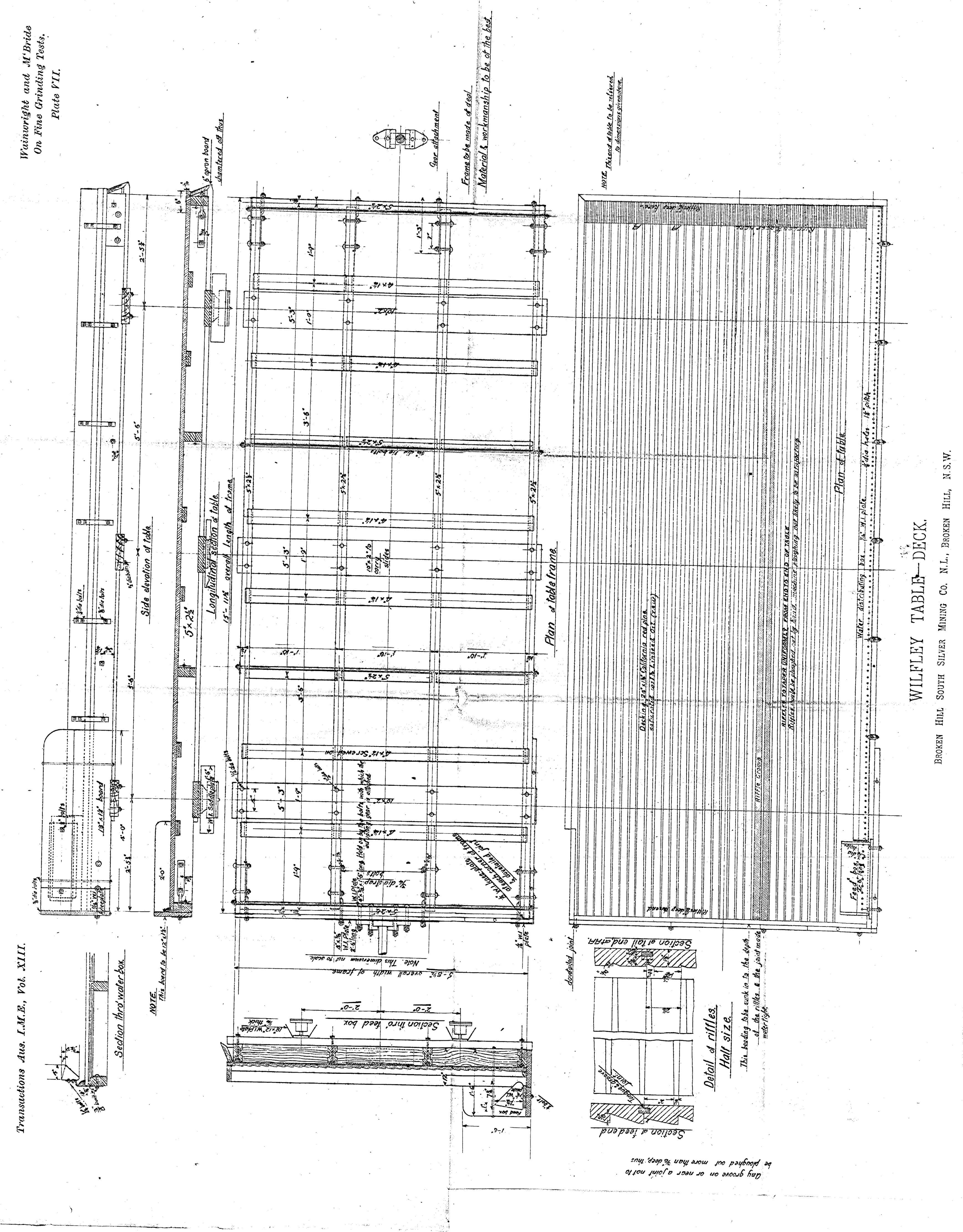
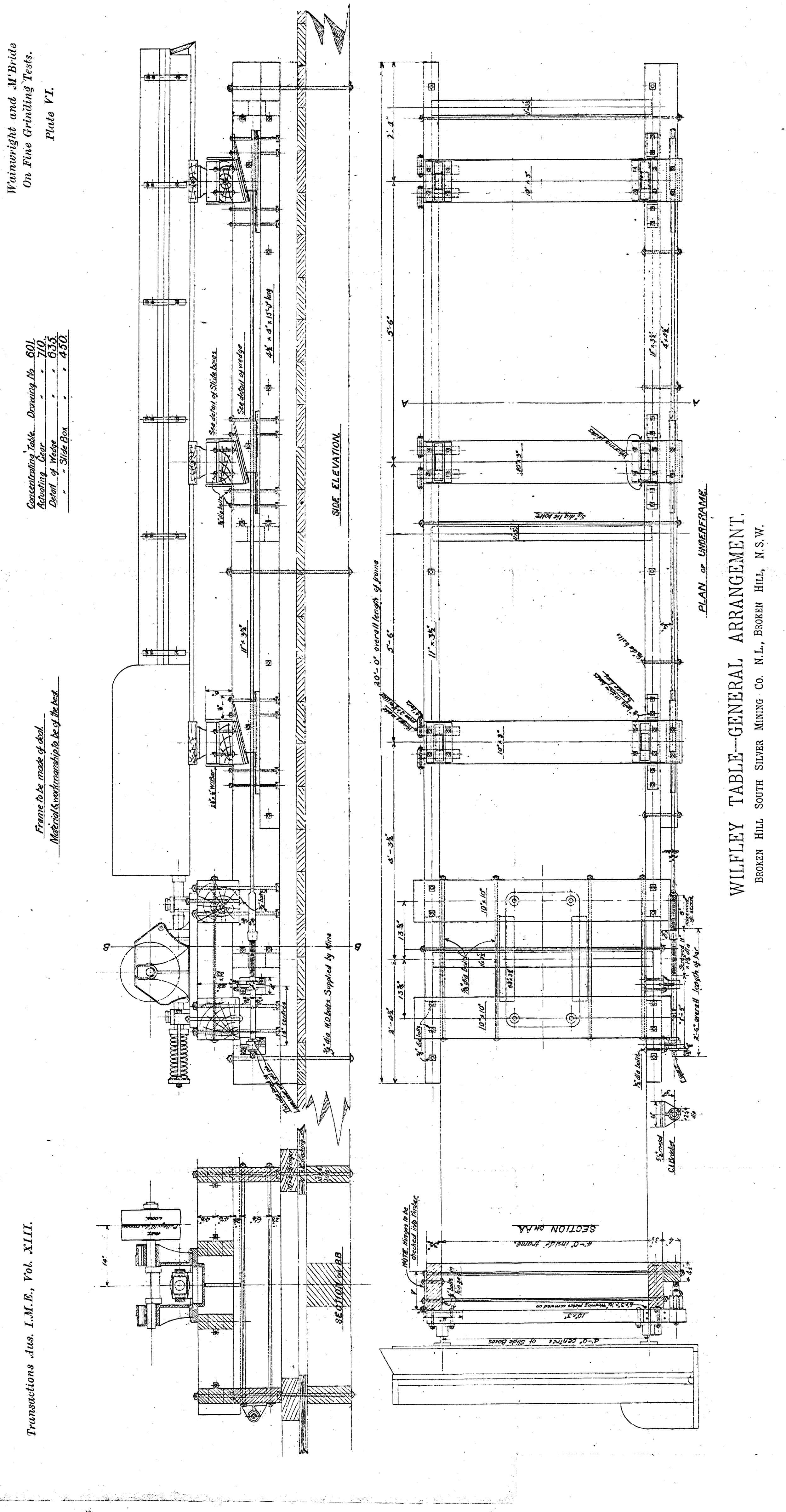
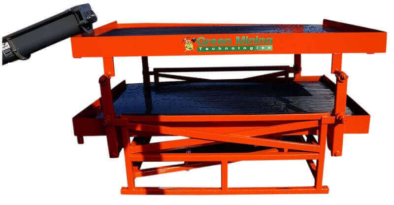
Wilfley Shaker Table Plans and Drawings
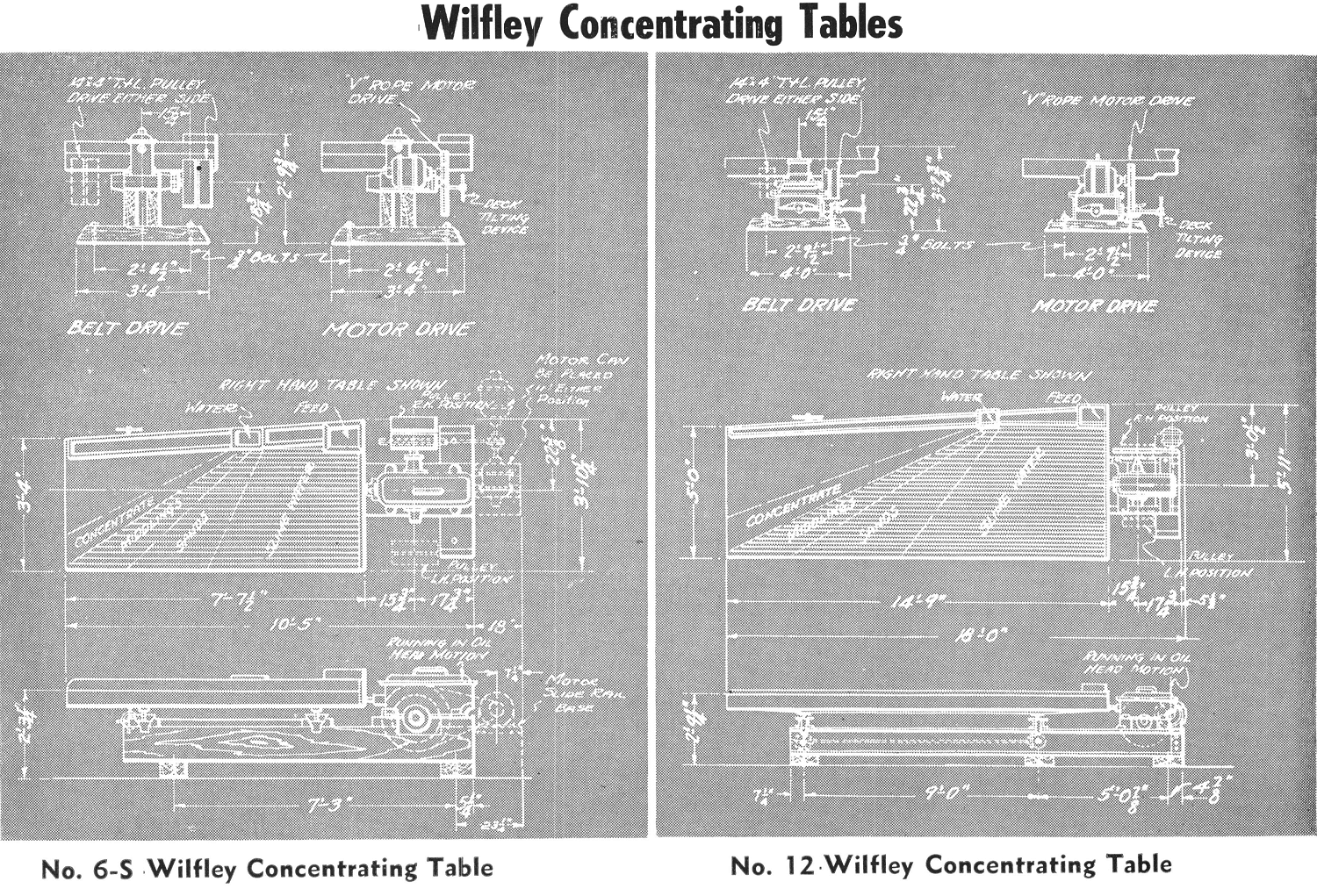

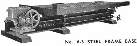
This is the latest improved type, single deck Wilfley Concentrating Table with steel frame base. Oil-immersed rocker bearings carry the cast iron separators which are bolted to the frame; maximum rigidity and alignment of mechanical parts are assured with this concentrating table.
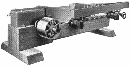
Similar construction to No. 6 tables, with the exception that the deck is smaller, having approximately one-fourth the area of the No. 6 Wilfley Concentrating Table; made with steel or wood frame, depending upon availability of materials, or can be furnished for concrete foundation if necessary. Used for pilot plant work.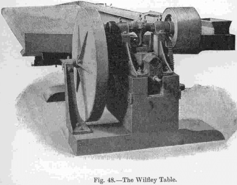
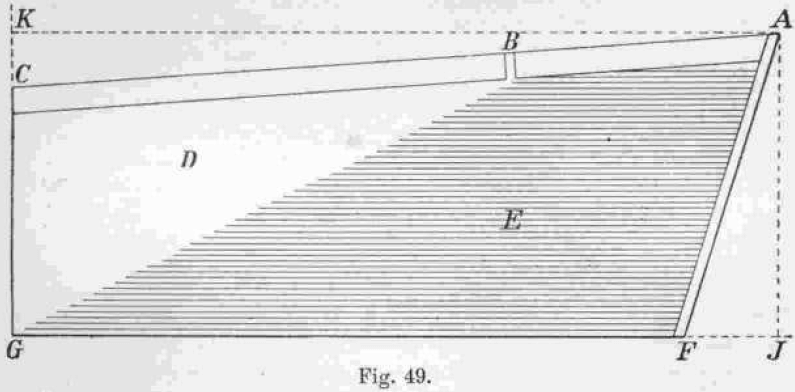
The Wilfley Table is shown in Fig. 48. It consists of a smooth shaking surface, of which Fig. 49 is a diagrammatic plan. The light, worthless material is washed down sideways towards F G by a flowing sheet of water, while the heavy concentrates are thrown towards the upper end, C G, against gravity by a longitudinal jerking action. The pulp is supplied from the wooden feed box, A B, 5 feet 1½ inches long, through a number of small holes. Clear water is supplied from the trough, B C, which is 9 feet 10½ inches long, also through small holes. A sheet of linoleum is tacked down over the whole table and is fully exposed at D. A number (usually 46) of wooden riffles shown at E are placed on the top of the linoleum and are nailed down. The longest riffle runs the whole length of the table, and the shortest riffle is about as long as the feed box. The riffles are ¼ inch high at the “head end,” A F, and taper down to nothing at the “ concentrates end,” C G. They are about ½ inch wide, the shorter ones being narrower, and are separated by 7/8-inch spaces so that the distance between centres is about 1 3/8 inches. The fall from the back, A B C, to the front, F G, can be adjusted by wedges, and is usually about 1 inch in 13 inches. The rise from the “ head end,” A F. to the concentrates end, C G, is usually set at about ½ inch. The length of the side F G is 13 feet 9 inches, and the width at C G is 5 feet ¼ inch. The length of the perpendicular from A on F G is 6 feet 1 inch, and from A on C G is 15 feet 9½ inches. The angle at G is a right angle and that at F obtuse. The shaking mechanism is situated at the end A F, and consists of a movement towards C G, beginning slowly and uniformly accelerated by means of a toggle joint, and a return movement towards A F effected by a spring, beginning suddenly and uniformly retarded. The effect of this vanning motion is to a certain extent similar to that of a bump delivered at the end C G, the concentrates moving uphill towards G. The length of the stroke is about ¾ inch and the number about 240 per minute.
The tailings pass over the front F G, and the concentrates over the end C G. The middlings pass over near G, in the last 16 inches of the front, falling into a special launder, whence they are returned to the feed box or sent to other machines.
The size of the pulp treated on this table is usually from 16 to 30 mesh. The table does not save the finest slimes, and the Wilfley slime table, which consists of a series of moving troughs with canvas bottoms, is recommended in some cases for the treatment of the tailings from the ordinary Wilfley tables. The capacity of the Wilfley table is given as varying from 12½ to 30 tons per day, the amount of wash water required being also variable. The power required is about 1 H.P. per machine.
