Table of Contents
The concentrate from the flotation section usually contains only 20 to 30% of solids as it leaves the cleaning machine and must be dewatered before being sent to the next department. The operation of dewatering is performed in two stages. First, the bulk of the water is removed in a thickener, from which the concentrate is discharged as a thick pulp ; as a rule the underflow contains 55 to 65% of solids, while 70 to 80% of the original water is recovered in the overflow as a clear liquid. The thickened pulp is then sent to a filter from which the solids are discharged as a cake containing about 10% of water.

The cost of removing the water by means of a vacuum filter is expensive as compared with a thickener and the latter machine is therefore always employed in the first stage of dewatering. A filter is essential in the second stage, however, as a thickener cannot be made to give a product dry enough to be stored in bins or handled economically in the smelting or other department which follows the filtering section.
Flotation Concentrate Thickeners
Of the various thickeners on the market those made by the Dorr-Oliver Company are the most widely used. They are of two types—viz., the Central Drive and the Traction Thickener—the second one being a more recent development which is superseding the other machine for some purposes.
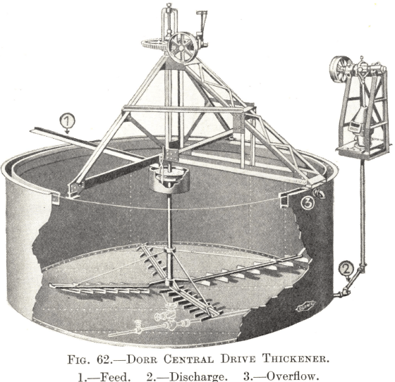
The Central Drive Thickener, which is illustrated in Fig. 62, is generally employed for concentrates. It consists of a cylindrical tank of iron, wood, or concrete, with a slow-moving raking mechanism in the bottom designed to scrape the solids that settle there to a central discharge cone. The pulp enters continuously at the centre of the tank on a level with the top, the solids sink gradually to the bottom, and clear water overflows the top of the tank into a peripheral launder for return to the flotation circuit. The raking mechanism is supported by a central vertical shaft and consists of four radial arms to which are fixed a number of short raking blades at evenly spaced intervals. The blades are set at an angle to the arms, so that, as they revolve with the shaft, they move the settled solids towards the discharge cone in the centre.  The vertical shaft is held in position by a superstructure mounted over the top of the tank, all bearings being above water level. The blades are normally kept a few inches clear of the bottom, but a lifting mechanism in the superstructure enables the whole assembly to be raised, in the event of a long stoppage, high enough to clear the thickest bed of solid material likely to settle on the bottom of the tank. The shaft is driven through a worm gear secured to the superstructure. Its speed varies according to the diameter of the tank, ranging from 10 ft. per minute in the smallest size to 20 ft. per minute in the largest (peripheral speed of the end of the longest rake-arm). The mechanism is designed so that the shaft can slide through the gear-wheel which drives it in order to enable the raking assembly to be raised or lowered whilst in motion. The thickener can be driven by belt and pulley from a line shaft, but it is more satisfactory to employ an individual motor for every thickener, mounting it in the superstructure and fitting it, if necessary, with a speed reducer.
The underflow of the thickener is discharged through a pipe connected to the cone in the bottom of the tank. The density of the product depends on its rate of discharge, which is generally controlled by means of a plug- valve in the pipe-line. Should the layout of the plant make it impossible for the pulp to flow to the filters by gravity, a Wilfley Pump can be used to elevate it provided that thickening is not carried too far, but if the product is very thick, it is best handled by a diaphragm pump. The Dorrco Pump is of the latter type. It is made by the Dorr-Oliver Company for use in conjunction with thickeners, and incorporates a device for varying the stroke, thus providing a positive method of regulating the flow.
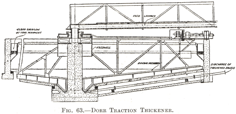
The Dorr Traction Thickener is shown in Fig. 63. It is, as a rule, only employed for concentrates when the diameter of the tank exceeds 50 ft. The thickening operation is performed on the same general principles as in the other type, but the design of the mechanism is different. It consists of a radial truss to the bottom of which is attached an arm carrying raking blades. The arm is a few feet longer than the radius of the tank, the extension beyond the centre being provided to increase the raking capacity near the discharge point. The inner end of the truss is supported by a bearing assembly which rests on a central column ; to its outer end is attached a traction wheel which runs on a flange or track round the outside of the tank. The traction wheel is driven by a motor mounted on the truss itself at a speed varying from 15 to 25 ft. per minute according to the size of the thickener. The feed enters at the centre of the tank as in the other type, clear water overflows into a peripheral launder, and the revolving blades scrape the settled solids into a discharge cone.
Central Drive Thickeners are made with tanks ranging from 6 to 100 ft. in diameter, but the larger sizes are not as a rule employed for concentrates, the Traction Thickener being preferable for diameters in excess of about 50 ft. Traction Thickeners are made in diameters of 8 to 300 ft. or more, and are commonly used in all sizes for dewatering tailings. The size of a concentrate thickener is determined by the tonnage of solid material to be dewatered, the amount of water in the pulp, and the settling rate of the solids. In the absence of specific data, it is usual, for the purposes of rough calculations, to allow 10-15 sq. ft. of tank area per ton of dry concentrate produced per 24 hours. The power required to drive the thickener mechanism is very small; it varies from ½ h.p. for the smallest to 7½ h.p. for the 300-ft. size.
https://www.911metallurgist.com/rotary-filter-capacity-installation
https://www.911metallurgist.com/rotary-disk-filter
