The electric operation and design features of the 11,000 H.P. variable speed SAG mill gearless drive is presented. The function of the frequency-converter, control system drive and lubrication systems are described. An analysis of the harmonic characteristic in the Supply System and Motor is presented, and the dynamic development of the stator current, speed and the magnetic flux in the start-up process of the drive is evaluated. Besides, the most important aspects in the commissioning and maintenance of the drive are analysed.
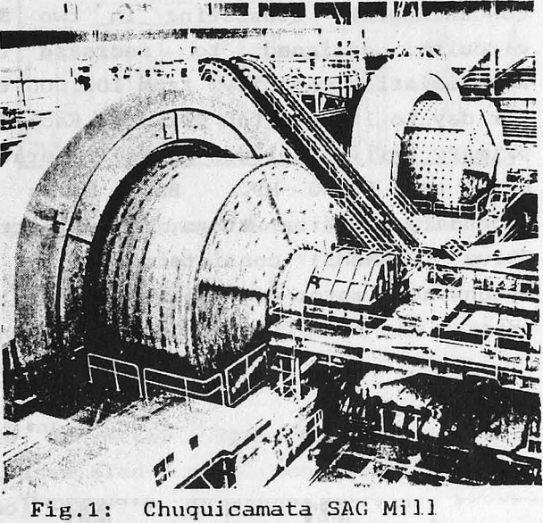
During January, 1989, the Chuquicamata Division of CODELCO-CHILE put into operation the project AMPLIACION A-2 CONCENTRADORA, consisting in two SAG circuits, designed to increase the beneficiation capacity from 102.000 ton per day to 153.000 ton per day. Each SAG primary mill (Boliden-Allis) operates with two 5.000 HP. Ball Mills as secondary grinding stage. The Electric Drive (SIEMENS) consists a 11.000 HP synchronous motor of variable speed.
General Description of the Drive
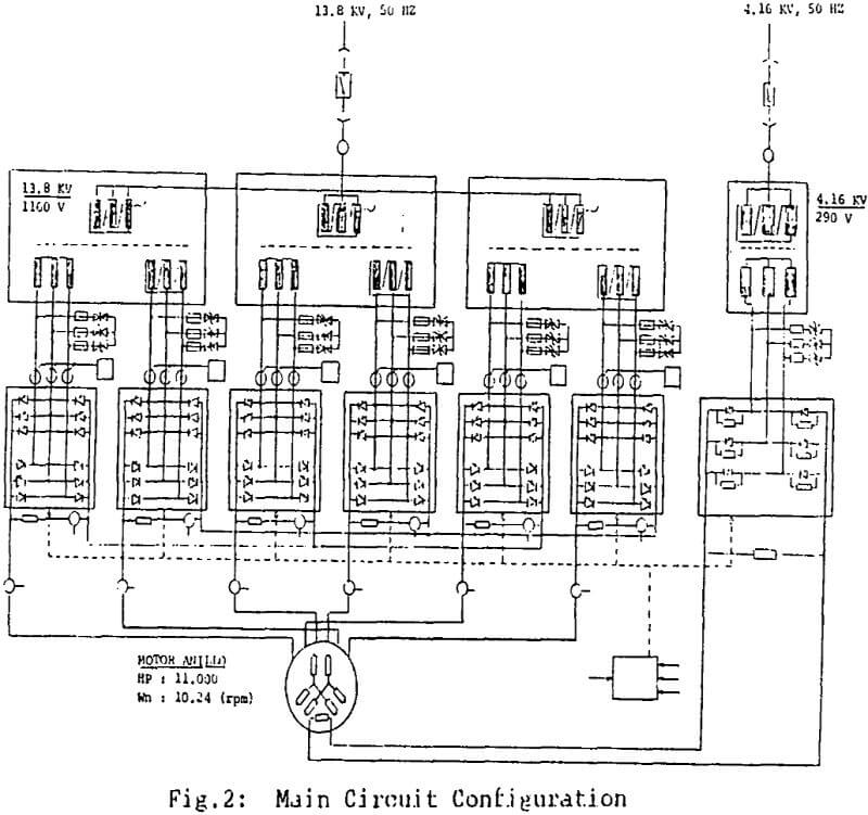
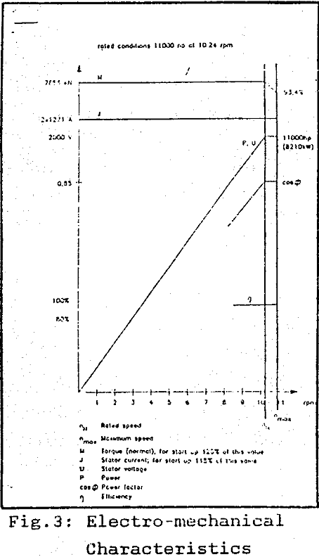
The SAG Mill Drive is mainly formed by a 11,000 HP. Ring Type Synchronous Motor of double winding, fed by two Three–Phased Cycloconverters. The rotor has salient poles without dumping windings and it consists of 72 poles. The cycloconverters work in the out-of-circulation current mode and they are connected to a 13.6 MVA transformer.
Assembling and Construction
The Ring Motor Stator has a total weight of 225 tons and it is divided in three parts. The outer diameter is 18 meter and the inner diameter is 12 meter. For assembling each stator part at site two 150 ton capacity mobile cranes were used. Trained operators made the coil joints between the stator segments.
The winding general characteristics are: 4 turns by coil, 8 coil by slot, 540 slots and the lead section is 400 mm2.

Component Characteristics
The three-phased Cycloconverter consists of six bridge type converters connected in antiparallel. The conmutation is natural to the frequency in the network.
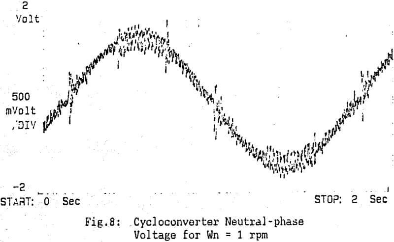
The output voltage has a sinoidal modulation until it reaches the maximum converter output voltage. After that, the converter is controlled with a modulation approximately trapezoidal. The change in the converter functioning is carried out leaving a “dead time” of 1 mseg aprox., once the current has become zero and the thyristor blocking voltage detection circuit assure the lack of current (current “bounce” phenomenon).
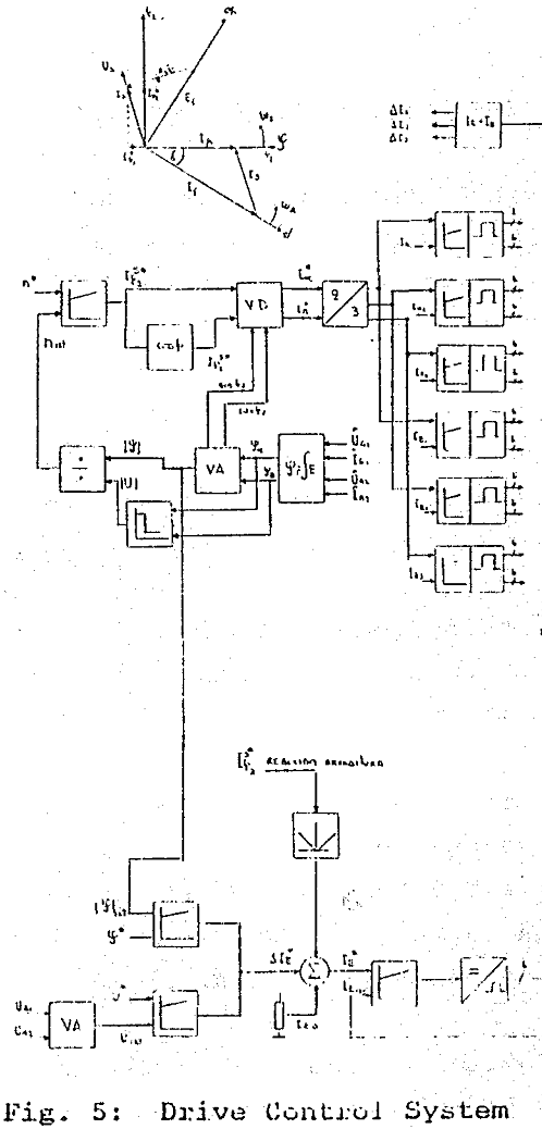
The functioning of the Drive Control System is based on the Oriented Field operation principle. In general, the system consists of four control loops: stator current control, excitation current control, the magnetic flux control and the speed control.
The stator current component which is proportional to the torque (i42) is determined by the speed control loop, and the magnetizing current component (i41) is calculated from the power factor relation in which the machine is desired to function.
Drive Evaluation
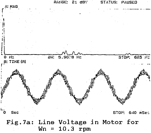
The characteristic currant harmonics having special relevance are the 11th and 13th. It also appear some harmonics that corresponds to the sidebands of these characteristic frequencies defined by (16 x n x F), where F is the cycloconverter output frequency, equal to 6.2 Hz.


