Table of Contents
- How Important is the Length of the Grinding Mill to Comminution
- Open and Closed Circuits Single and Two-Stage Grinding
- Advantages of open circuit grinding
- Advantages of closed circuit grinding
- Advantages of single stage grinding
- Advantages of two-stage grinding
- Grinding Circulating Load
- Grinding Equipment Rotating Speed
- Comminution Power & Capacity
This page is devoted to the subject “From the Comminution Theory to Practice by selection of the correct Process Equipment” by taking you step by step through some of the variables encountered in the specific part of Comminution called grinding and how each of these affect your operations. Should it be possible to reduce all of these variables to a simple mathematical formula the selection of a grinding mill would, of course, be simple. Many approaches to this have been made but to date a foolproof formula, both mathematically and practically applicable, has not been devised. We must, therefore, take each variable into consideration on its own merits and then correlate such ideas into a single selection. To do this a broad experience and understanding of the complete subject of grinding is essential. This is a part of the problem of your engineers and our own consulting staff. General points have been discussed briefly on wet or dry grinding, and fineness of grind. Two main categories of grinding equipment, namely rod mills and ball mills, have also been mentioned. Whether grinding is to be performed wet or dry, or in a ball mill or rod mill, a choice must be made between open or closed circuit. Other factors which require thought are mill size, speed of mill rotation, moisture content, retention time, circulating load, type and sizes of grinding media, mill pulp level, mill shape, power, and relation between diameter and length. These all influence operating results and are evaluated and incorporated in the selection and design of the Mill.
Mills are essentially cylindrical in shape and this design has been selected for very definite reasons. Mill capacity is a function of the mill volume and the load of grinding media. Therefore to obtain a mill of greatest capacity for any given space, pure logic dictates a mill having the greatest volume. While a square section would provide the greatest volume, smooth continuity of operation and uniformity of media action must also be considered and thus a true circle is the only practical answer. Should the diameter vary from one end to another there is but one thing which occurs reduced volume, or in other words, reduced capacity.
The cylinder simplifies mill construction, resulting in a minimum amount of maintenance and reflecting in less downtime. Power wise, cylindrical mills provide the most economical piece of equipment for grinding work. Floor space for any mill is proportional to the diameter of the mill and its length. Therefore, floor space is kept at a minimum. A mill, keeping uniform diameter throughout its full length obtains maximum volume for a given floor space.
How Important is the Length of the Grinding Mill to Comminution
The relationship of mill diameter to length is of considerable importance. Rod mills should have a length greater than the diameter to avoid entanglement of rods. The construction of ball mills is different in that the diameter may be larger, equal to, or smaller than the length.
The selection of mill length is dependent upon the size of feed, size of product and type of grinding circuit selected. Considerations given a short mill are the reduced floor space, shorter retention time producing less fines in the discharge product, and the possibility of producing a slight amount of tramp oversize particles. Corresponding conditions to be expected from a longer mill are greater floor space requirements, higher capacity (closely proportional to mill length), greater retention time thereby producing a finer mill discharge product and a greater amount of extreme fines, less tramp oversize in the product. Since most mill variables act as a function of the mill length, this consideration is relatively simple. On pages 10 and 11 considerable discussion is provided on the subject of mill diameter.
Open and Closed Circuits Single and Two-Stage Grinding
The method of operating a grinding mill may be classified into two methods, open circuit or closed circuit. In open circuit grinding feed enters one end of the mill at a predetermined rate so as to make the desired finished product during a single pass through that mill. In other words there is no size classification made on the discharge product. One important application is on ores containing damp and clay-like material which causes difficulty in fine crushing. This problem is generally solved by wet grinding in a rod mill or in this case it may be called wet fine crushing.
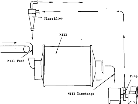
In closed circuit grinding the feed enters one end of the mill and is discharged from the other end into some type of classifier. This classifier is to limit maximum particle size removed from the mill circuit. The oversize material is returned to the grinding mill for additional size reduction. Such material returned to the mill is defined as the circulating load. Classifying equipment may consist of vibrating screens on coarse separations for wet or dry grinding. For wet grinding in the finer size ranges wet classifiers and/or cyclones are employed, generally to make a size separation from 20 mesh down to 325 mesh. Under dry grinding conditions air classifiers are used to make the size classification.
Single stage grinding may be defined as grinding original feed to finished size in a single mill. It may operate in either open circuit or closed circuit.
Two stage or multiple stage grinding may be defined as grinding in two or more units with each unit making a step in size reduction. Each mill may operate either as open circuit or closed circuit.
Advantages of open circuit grinding
1. Simplicity of mill layout.
2. May be used where classifying is not practical.
3. May be used where control of product size is not important.
4. The use of rod mills will produce an ideal fine feed for ball mills.
5. May be used where classifier dilutuion would be objectionable.
Advantages of closed circuit grinding
1. Provides a close control of finished product size.
2. Mill capacity is greatly increased.
3. Power requirements per ton of finished material are lower.
4. Less overgrinding or production of extreme fines.
Advantages of single stage grinding
1. Less equipment to purchase install and maintain.
2. Less floor space requirements.
Advantages of two-stage grinding
- Less overgrinding.
- Provides a simplified fine crushing plant and grinding section.
- May be used to increase capacity of existing single stage operation.
- Provides an opportunity for recovery of desirable material between stages of size reduction.
Grinding Circulating Load
Generally speaking circulating loads for rod mill operation will be less than 200%. In most cases it will more closely approach 100% to 120%. In ball mill operations the circulating load will vary between 300% and 1000% depending upon the grind required and type of material. As an average it will approach 350%.
Grinding Equipment Rotating Speed
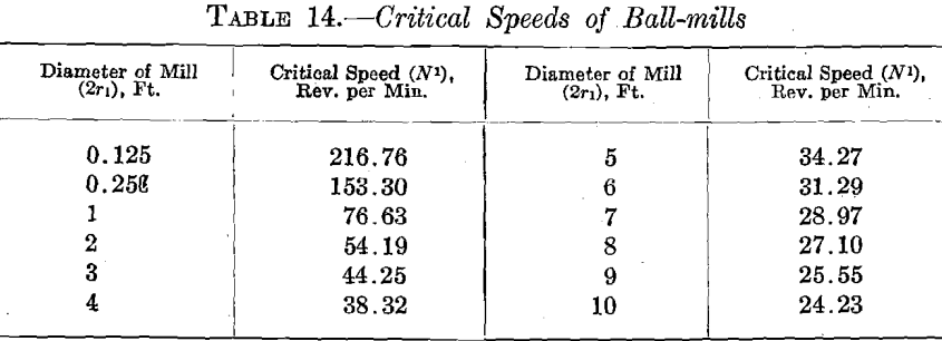
Proper speed, or most efficient speed, at which mills are to operate depends upon the action desired by the grinding media, the amount of media, its size and shape, percentage of solids in each mill, and shape of liners. In the following discussion we refer to critical speed applying to ball mills and peripheral speed referring to rod mills. Reference graphs giving these speeds for various mill diameters will be found below.
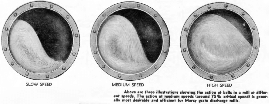
Critical speed may be considered as the speed at which an infinite particle will continue its travel around the periphery of the mill, thus becoming part of a flywheel action. Grinding balls actually will not centrifuge at this theoretical critical speed since they are larger than an infinite particle and also because of slippage. The following table illustrates the action of a normal ball charge at various percentages of critical speed.
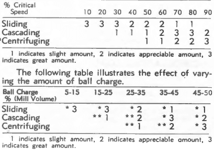
Generally speaking ball mills operate within the range of 50% to 90% of critical speed. The average is found to be approximately 75%. Pebble Mills have been found to operate more efficiently at higher speeds than ball mills. When reaching the higher percentages of critical speed caution must be used and consideration given the action of the scoop feeder.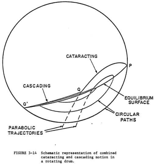
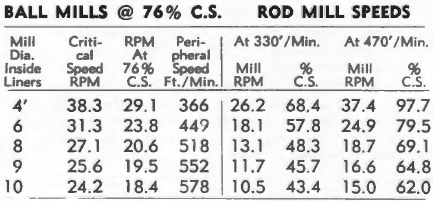
When considering rod mills, peripheral speeds only should be considered. In the case of ball milling, with a free moving grinding medium, ball paths obtained are based on critical speeds. In a rod mill with a comparatively rigid grinding medium, a certain cascading and roll of rods are obtained, which does not resemble the action of loosely projected ball paths. Therefore to simulate similar rod actions in mills of various diameters it is necessary to operate between 60% and 98% of critical speed. Therefore, Critical Speed is misleading if used in conjunction with rod mills. It has been found that low pulp level rod mills show increases in efficiency as peripheral speeds are increased from 300′ per minute to the present practical maximum of around 500′ per minute.
To illustrate the comparison between critical speeds and peripheral speeds and the misleading use of critical speed for rod mills, we submit the following illustrative table:
Theoretically critical speed is the point at which centrifugal and gravity forces acting on an infinite particle traveling on the shell liner offset each other or become equal. The formula used in calculating critical speed is shown on the graph below.
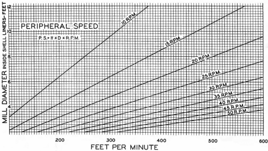
The above graph provides peripheral speeds for various mill diameters. Such speeds are measured on the inside diameter of shell liners.
Comminution Power & Capacity
Often grinding capacity and power are used hand in hand since power is an index to the potentialities of any grinding mill. The grind achieved as in direct relation to the power applied in rotating a mill. This rotation transmits energy input to the grinding media and energy is consumed in reducing particle sizes. When any particle is split, producing two or more smaller particles, the total surface area of the smaller particles will be greater than the surface area of the initial size. Therefore surface area often is used to express the amount of grinding work which is performed.
There are two methods of looking at power. First and easily understood is the reference to connected horsepower, or the actual consumed horsepower required to drive the mill. The second is basing power on the amount of work done. We prefer to express this as kilowatt hours per ton of material ground. The following formula containing three factors may be found useful in calculating power consumed per ton of material ground. Wherever two of the factors are available, the third may easily be solved.
HP = KWH/ton x tons per 24 hours/17.9
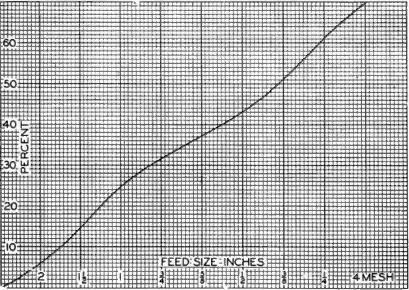
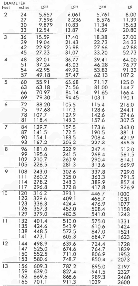
There are several variables in mill horsepower —the most important has to do with mill diameter. Several of these variables also reflect similarly on capacity. There have been various statements made as to how power and capacity vary with mill diameter each using a figure of the diameter raised to some power such as D3 D2.65 D2.6 and D2.5. For your convenience we have listed on page 11 a table giving these various diameters raised to the appropriate figures. We have found in the low pulp level mills that the capacity varies closely as the diameter cubed. The mill power varies closely as the diameter to the 2.5 power. With overflow type mills, or high pulp level mills, the theoretical exponents more closely approach the 2.6 or 2.65 power. The difference lies in the waste of energy when transmitted through a cushioning deep quantity of pulp.
Power required in relationship to mill length is a straight line function or direct proportion within limits. In other words each foot of mill will require a definite amount of power. Capacity of a mill also varies in the same manner.
Example grinding mill power calculation:
You are operating an 8 feet diameter Ball Mill consuming 245 HP and grinding 500 tons per day to 65 mesh. What will be the capacity of a 5 feet grinding Mill? From the table below, the 8 feet diameter mill cubed is 512; the 5 feet diameter mill cubed is 125; the 8 feet mill diameter to the 2.5 power is 181; and the 5 feet mill diameter to the 2.5 power is 55.91. Such diameters are inside new liners.
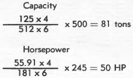
Therefore the 5 feet mill will have a capacity of 81 tons and will consume 50 HP.
Power consumed is a reflection of the fineness of grind. The finer a material is ground the more power is consumed.
Power consumption is also a reflection of the amount of media carried within the mill. The maximum power requirements for any mill will be when it is 45% to 50% filled with grinding media. Above or below this power drops off. Similarly mill capacity will behave the same way. Within limits the effect of adding or decreasing grinding media will be proportional to that weight.
Power is again reflected in mill dilution. A mill carrying a high percentage of solids will consume less power than a mill carrying a low percentage of solids.
The above refers to wet grinding. Under dry grinding conditions it has been found that the power will be between 60% and 90% that of a wet grinding mill. Wet grinding capacity will be 1½ to 2 times that of dry grinding.
 |
|
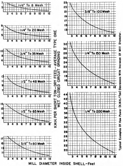
| The above graph illustrates how power consumed for various grinds changes with ball mill diameter. It is noted that as the diameter of the mill increases the kilowatt hours consumed per ton decrease. This shows the advantage of selecting as large a diameter mill as possible for any grinding application. (Curves may be used within limits of about 3 or 4 feet diameter variance.) |
