Table of Contents
As part of its research program on column flotation, we performed studies on (1) column flotation amenability and comparison with conventional flotation results for over 15 mineral systems, (2) alternative methods for improving column bubble generation systems, (3) mineral behavior within a column, and (4) the effect of changes in column operating parameters on flotation grade and recovery.
Based on results from these studies, flotation columns (1) are capable of producing higher grade concentrates in fewer stages than conventional flotation cells at equivalent or increased recoveries, (2) require less retention time than conventional flotation cells, and (3) can be divided into cleaning and collection zones that have characteristic mineral-upgrading-per-foot values.
Attempts to improve the column air sparger have led to the development of a superior external bubble generation system, which can (1) achieve increased air holdups, (2) produce bubbles from 400 µm to 4,000 µm average bubble diameter with minimal frother addition, (3) provide superior bubble size control, and (4) be maintained without column shutdown.
Efforts are continuing to improve column flotation and transfer successful technology to industry.
The U.S. Bureau of Mines initiated testwork on column and fine-bubble flotation at its Salt Lake City Research Center (SLRC). The purpose of this research was to investigate promising mineral beneficiation techniques and develop their use for transfer to private industry, and by so doing, to strengthen the domestic minerals industry and expand development of strategic and critical metals resources. This research program consisted of investigating the application of column and fine-bubble flotation to various mineral systems. The consistently observed advantages and superior performance of the laboratory flotation column compared with a conventional bench flotation machine within the first few months of testing inspired intensified investigation of column flotation and development of an extensive laboratory column test facility. Column flotation studies at the SLRC have expanded to include investigation of:
- Column flotation amenability for over 15 different mineral systems and comparison with conventional flotation results (McKay, 1986; Foot, 1986; McKay, 1986a; McKay, 1987).
- Mineral behavior and trending within the flotation column (McKay, 1987).
- Column operating parameters and their effect on column performance (McKay, 1987).
- Application of flotation columns as roughers (McKay, 1986).
- Extraction of multiple components from a single ore using flotation columns exclusively.
- Automation and control of a flotation column.
In addition, in an attempt to better understand fine-bubble generation and construct a bubble source for fine-bubble flotation testwork, research led to development of a mechanically simple method for generating bubbles. The bubble generator functions as a unit operation external to the flotation column and allows for enhanced air holdups and bubble size control compared with typical porous spargers. Development of this external bubble generation unit further led to:
- Testing of parameters affecting bubble generation.
- Design and testing of scaled-up external bubble generation systems for commercial usage.
- Exploration of alternative uses for the bubble generation system.
This paper contains an overview of the Bureau’s research on column flotation and bubble generation at its SLRC.
Test Facilities
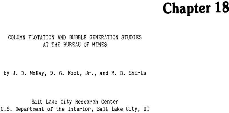
In order to increase column flotation testing capabilities, facilities at the SLRC were expanded from a single 6.35-cm (2.5-in) diam by 5.4-9-m (18-ft) tall clear Plexiglas acrylic sheet sectionalized column to include six additional 6.35-cm (2.5-in)-diam by 3.96-m (13- ft)-tall clear plexiglass sectionalized columns for flotation testing (Figure 1) as well as a 0.3-m (1-ft)-diam by 3.66-m (12-ft)-tall column, a 0.91-m (3-ft)-diam by 1.83-m (6-ft)-tall column, and a 1.83-m (6-ft)-diam by 1.83-m (6- ft)-tall column for sparger design, performance and scaleup testing.
Each of the 6.35-cm (2.5-in)-diam test columns has 2.86-cm (1.125-in)-diam ports located at 0.3- m (1-ft) intervals along its entire length to permit extensive adjustment of injection and sampling locations. Each column is further equipped with solenoid-activated sampling valves to permit extraction of samples along the column length during continuous column testing; manometer tubes with adjustable water sprays for air holdup and level determinations; feed, tailings, and wash-water pumps; wash-water spray tips; a column rinse-water system; a steady feed tank; and a complete external bubble generation system. This muItiple-column system is completely versatile and permits either multistage column testing or concurrent column testing of different mineral systems.
The 0.3-m (1-ft)-diam by 3.66-m (1 2-ft)-tall, 0.91-m (3-ft)-diam by 1.83-m (6-ft)-tall, and 1.83-m (6-ft)-diam by 1.83-m (6-ft)-tall columns permit both quantitative and qualitative evaluation of commercial size- air sparging systems such as the Bureau’s external bubble generation system.
The recent addition of a Honeywell distributed- control computer system provides capabilities of (1) up to 64 control loops; (2) keyboard control of process variables; (3) dynamic flowcharting; (4) real-time and historical data trending, data storage and manipulation; and (5) redundant control by stand-alone controllers. The Bureau’s column flotation test facility at the SLRC is a premier laboratory for studies of column flotation and automation studies.
Column Test Results on Specific Ores
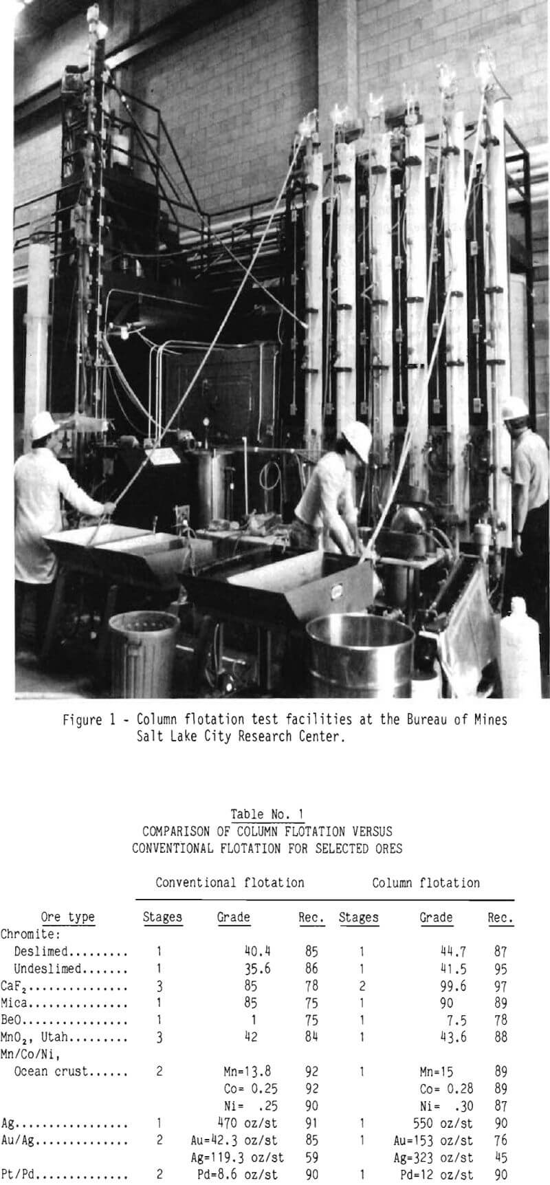
As part of its research on column flotation, the Bureau has performed testwork using the equipment previously described on a variety of mineral systems and compared results with those achieved in conventional laboratory flotation machines. Comparative examples, representative of column flotation test results, are summarized in Table 1.
Chromite Ore
On Benbow chromite ore containing 19.1 pct Cr2O3, from the Stillwater Complex in Montana, fine-bubble column flotation of deslimed chromite ore produced a 44.7-pct Cr2O3 rougher concentrate at 87-pct recovery, whereas conventional flotation produced a 40.4-pct Cr2O3 concentrate at 85-pct recovery. Flotation of undeslimed chromite produced a 35.6-pct Cr2O3 concentrate with 86-pct recovery using conventional flotation, a 41.6-pct Cr2O3 concentrate with 94-pct recovery using coarse-bubble column flotation, and a 41.5-pct Cr2O3 concentrate with 95-pct recovery using fine-bubble column flotation. Column flotation required only 4-5 min retention time compared with retention times of 8-10 min required for conventional flotation.
Tests were also conducted to compare the flotation response of discrete chromite size fractions using conventional and column flotation. On 65- by 150-mesh material both techniques produced similar results. However, on the plus 65-mesh and minus 150-mesh size fractions, column flotation, particularly using fine bubbles, achieved higher grades and recoveries than did conventional flotation.
Fluorite Mica Beryl Silica Ore
A continuous column flotation system was constructed and operated to recover fluorite, mica, glass sand, and beryllium from a Nevada ore containing 14 pct CaF2, 67 pct SiO2, and 0.2 pct BeO. A 99.6-pct CaF2 first cleaner concentrate was produced containing 97 pct of the fluorite. A 90-pct mica product with 89-pct recovery, a 99-pct SiO2 glass sand product with 96-pct recovery, and a 7.5-pct BeO product with 78 pct recovery were also produced from the ore using the column flotation system. Best conventional flotation pilot plant results were an 85-pct CaF2 second cleaner concentrate with 78-pct recovery; an 85-pct mica product with 75- pct recovery, and a 1-pct BeO product with 75- pct recovery. No SiO2 glass sand product was recovered. Average retention time for fluorite
column flotation was only 3 to 6 min compared with a 15-min retention time required for conventional three-stage flotation.
Comparison of flotation response of fluorite size fractions for conventional and column flotation indicates that column flotation fluorite rougher grades were an average of 34 pct higher than conventional flotation rougher fluorite grades. Recoveries from column flotation were on average only 8 pct lower than those from conventional flotation, and material would be lost during subsequent conventional flotation cleaning stages.
Manganese Oxide Ore
Grades and recoveries achieved by conventional and column flotation were similar for a Utah manganese ore containing 14 pct Mn. Conventional flotation using a rougher and two stages of cleaning produced a 42-pct MnO2 concentrate with 84 pct recovery, while a single pass through the column produced a 43.6-pct MnO2 concentrate with 88-pct recovery. Column flotation eliminated the cleaning stages required in conventional flotation.
Manganese Crust Material
Flotation studies on cobalt-rich manganese ocean crusts from the Exclusive Economic Zone, containing 6 pct Mn, produced a 13.8-pct Mn conventional cleaner concentrate with 92 pct recovery, while a single pass through the column produced a 15-pct Mn concentrate with 89 pct recovery. The maximum achievable grade was 15.8 pct. Column flotation could lend itself well to shipboard processing, thus reducing materials handling and disposal problems, as only high-grade concentrates would be transported and tailings could be discarded to the ocean floor.
High-Grade Silver Ore
Column flotation greatly reduced reagent consumption in treating a silver ore from Washington State containing 39 oz/st Ag. Conventional flotation produced a 470-oz/st concentrate with 91-pct recovery. Column flotation, successful only after reducing the collector dosage by 80 pct, recovered 90 pct of the silver in a concentrate assaying 550 oz/st.
Precious Metals Ore
Fine-bubble column flotation of a Nevada gold-silver ore containing 0.57 oz/st Au and 1.7 oz/st Ag produced a first cleaner concentrate assaying 3.6 times higher in gold and 2.7 times higher in silver than a concentrate produced under the same test conditions using conventional flotation at comparable recoveries. Conventional flotation performed by an independent metallurgical laboratory produced a cleaner concentrate containing 42.3 oz/st Au and 119.3 oz/st Ag with recoveries of 55 and 53 pct, respectively. Fine-bubble column flotation produced a 153- oz/st Au and 323-oz/st Ag cleaner concentrate with 76 and 45 pct recovery, respectively. Direct comparison of recoveries is not practical in this case because the conventional flotation was preceded by gravity concentration (which recovered an additional 30 pct of the gold and 6 pct of the silver), whereas column flotation was not.
Platinum-Palladium Ore
Conventional flotation of a platinum-palladium-bearing ore from the Stillwater Complex In Montana containing 0.10 oz/st Pt and 0.17 oz/st Pd succeeded in producing a first cleaner concentrate containing 2 oz/st Pt and 8.6 oz/st Pd with 89 and 90 pct recoveries, respectively. Column flotation using the Bureau of Mines bubble generation system succeeded in producing a rougher concentrate assaying 3 oz/st Pt and 12 oz/st Pd. Palladium recovery was approximately 90 pct; however, platinum recovery was calculated as 61 pct but is suspect because the tailings product platinum content was sufficiently low that a difference of 0.01 oz/st resulted in a difference of approximately 11 pet in calculated recovery.
Mineral Behavior Within the Column
The flotation column can be divided into several zones. These zones (Figure 2) include:
- Cleaning zone—froth phase: Region extending upward from the pulp-froth interface to the column overflow.
- Cleaning zone—pulp-froth interface: Region of arbitrary length at the pulp froth interface. This region was assigned the space from 0.15 m (0.5 ft) above the interface to 0.15 m (0.5 ft) below the interface.
- Cleaning zone—pulp phase: Region extending downward from the pulp-froth interface to the feed injection port.
- The collection zone: Region extending downward from the feed injection port to the lowest air sparger.
Research conducted by the Bureau of Mines to obtain and analyze column mineral upgrading profiles for fluorite, calcite, and silica (Figure 2) indicates that the cleaning zones and collection zone have characteristically different values of mineral upgrading per foot of column length and behave independently of one another. Also, results indicate that the collection zone is responsible for primary mineral recovery. The cleaning zone—pulp froth interface and cleaning zone—froth phase were the most efficient zones for mineral upgrading.
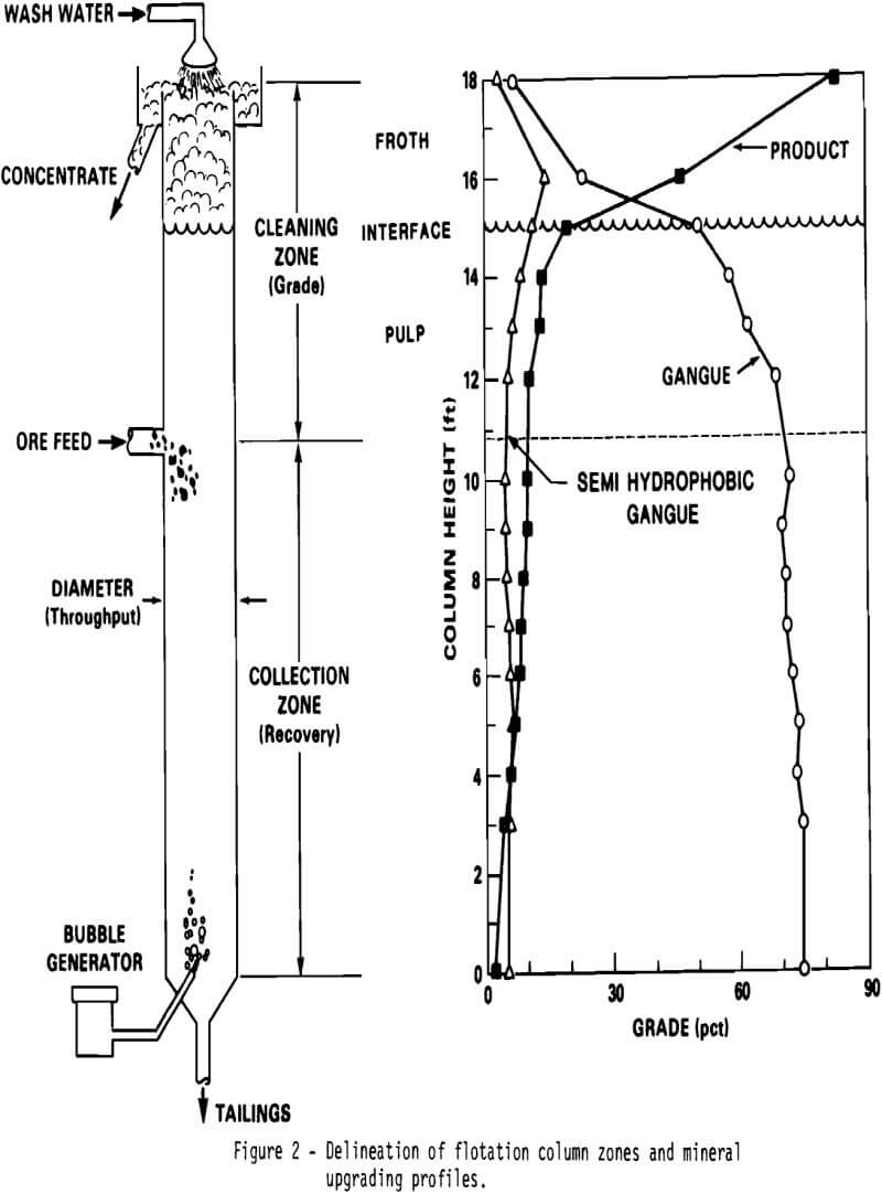
The cleaning zone—pulp phase had substantially lower mineral-upgrading-per-foot values than either one of the other cleaning zones.
Column concentrate grade is achieved in, and strongly tied to, behavior of the froth phase zones, whereas primary mineral recovery is achieved in, and closely tied to, behavior in the collection zone. Secondary mineral recovery (that is, recovery of minerals stripped from bubbles in the froth phase by wash water) is accomplished in, and related to behavior in the cleaning zone—pulp phase. The magnitude of the contribution of each of the zones within the pulp and froth phases varies with mineral system and column operating conditions. By examining the contribution of each of the four zones independently, the entire column length can be efficiently designed for a given mineral system.
As shown in the mineral profile in Figure 2, effective rejection of semihydrophobic minerals, such as calcite in fluorite flotation, was found to occur only within the cleaning zone—froth phase. While hydrophilic silica was rapidly rejected even in the cleaning zone—pulp phase, calcite was concentrated along with the fluorite well into the cleaning zone—froth phase, where it was gradually rejected.
Bubble Generator Development
During the initial stages of research on column and fine-bubble flotation, a literature survey was performed to ascertain various methods for generation of fine bubbles. Three general techniques are employed for generation of bubbles, particularly in wastewater treatment facilities, including:
- Electrolytic bubble generation
- Pressure dissolution
- Mechanical air induction
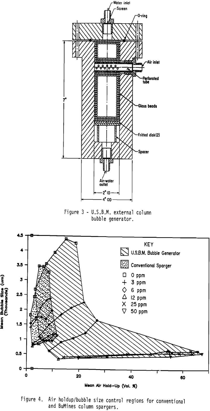
Based on the information gained from the survey and from preliminary experimentation, it was determined that the best practical approach was to combine pressure dissolution and mechanical air induction. By doing so, it was possible to produce bubbles from less than 400 µm to over 4,000 µm average bubble diameter. Furthermore, by using this method and adding small amounts of surface tension reductant (frother), the substantial air holdups necessary for mineral flotation can be achieved while maintaining fine bubble sizes. The resulting bubble generator, shown in Figure 3, is simply a pressure contact chamber into which water is introduced from the top and air from the side. The air-water mixture then contacts, under 60-70 psig pressure, in some media such as glass beads or quartz that improves the air-water mixing action. The mixture then exits from the bottom of the generator where it is released from pressure through a tip with a 0.10-cm (0.04- in)-diam injection hole. The bubble generator is capable of operating with any type of gas.
Bubble Generator Capabilities
A study was performed to compare the capabilities of the Bureau’s external bubble generator with a porous in-column type of sparger. Column air holdup (i.e., volume percent air present in the column) and bubble size were used as the objective functions to measure the generators performance. A fine-pore (40-60 µm), fritted-glass gas dispersion tube was used as a conventional sparger for comparison. Bubble size was tediously measured in situ by a direct photographic technique using a 35-mm camera with three closeup rings, high¬speed ASA 200 color slide film, and a 600-watt high-intensity light source. The bubbles were photographed superimposed on a photo-reduced grid attached to the inside face of a clear Plexiglas acrylic plug inserted in a flotation column. The developed slides were projected, and the bubbles were measured against the grid, which had a known spacing of 200 µm. Where possible, 100 bubbles were measured. From this procedure, bubble size distribution (by number) was obtained and a mean bubble size was computed.
Air holdups were measured by direct displacement using the average of three measurements. No solids were present during testing. Frother (Dowfroth 400) dosage was used to alter the solution surface tension and was varied from 0 to 50 ppm. At each frother dosage, the air flow rate was varied from a minimum mechanically feasible amount to the maximum flow rate achievable before flooding occurred. Flooding occurs when, instead of discrete bubbles, slugs of air are formed.
The results of this study, shown in Figure 4, indicate that, depending on the conditions, the Bureau’s bubble generator produced either coarser or finer bubbles than a porous-style column sparger with substantially increased air holdups. Perhaps most significantly, the results of this study demonstrate the tremendous advantage in bubble size controllability that is obtainable with the Bureau’s external bubble generator. Moreover, this control is achieved at reduced frother dosages and, independent of frother addition, bubble size may be extensively altered by changing the air flow rate.
Parameters Affecting Bubble Generation
A study was performed to determine which parameters affect the bubble generator’s performance. Performance was evaluated quantitatively by bubble size and column air holdup and qualitatively according to its mechanical operation. The parameters investigated included:
- Frother concentration
- Water temperature
- Operating pressure
- Injection tip
hole size
velocity - Bubble generator contact media
type
shape
size
Results of this study indicate that frother concentration, injection tip hole size and velocity (a function of pressure and tip hole size), operating pressure, and, to a minor extent, contact media size had an effect on bubble size and column air holdup. Water temperature had no discernible effect on bubble size or column air holdup.
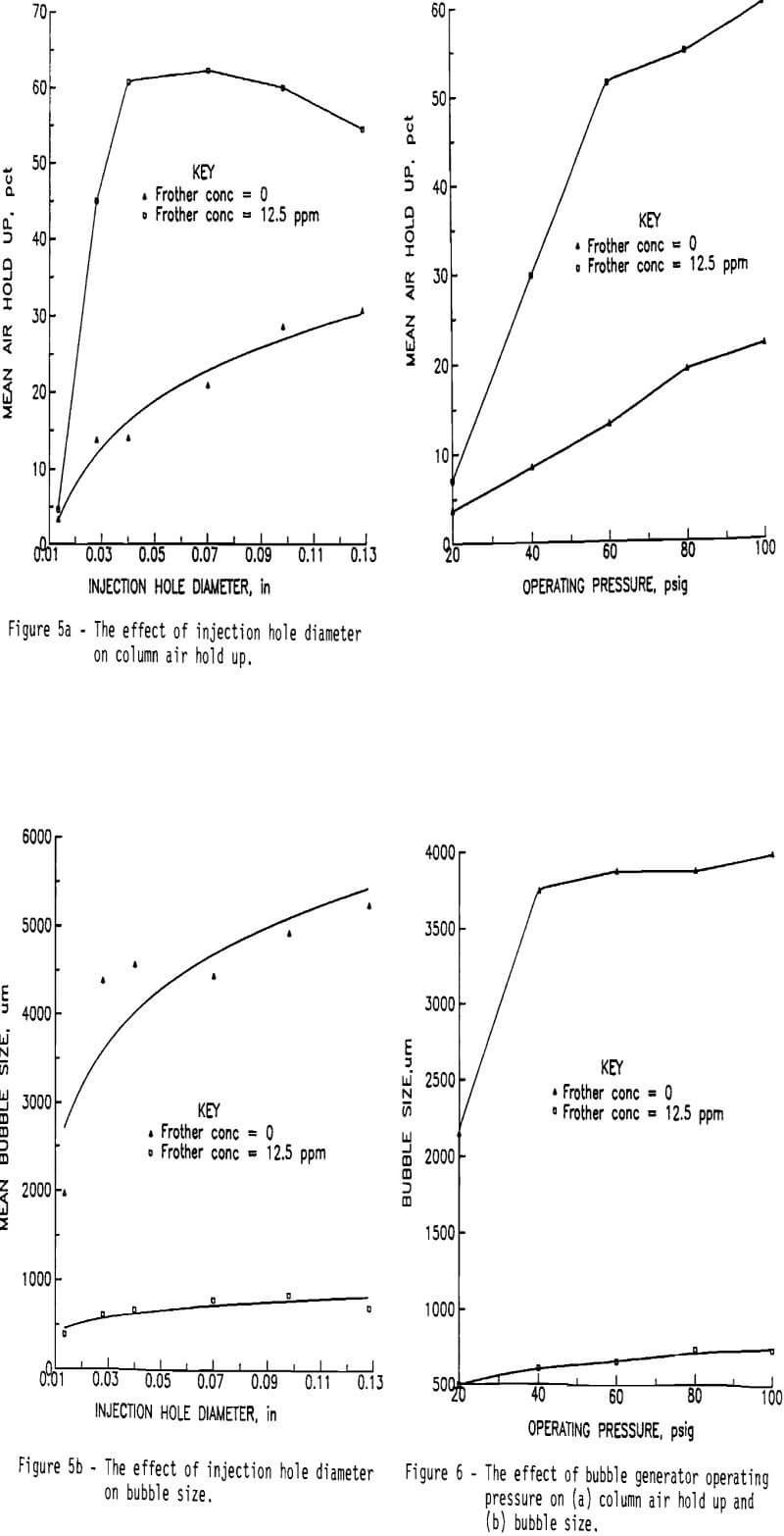
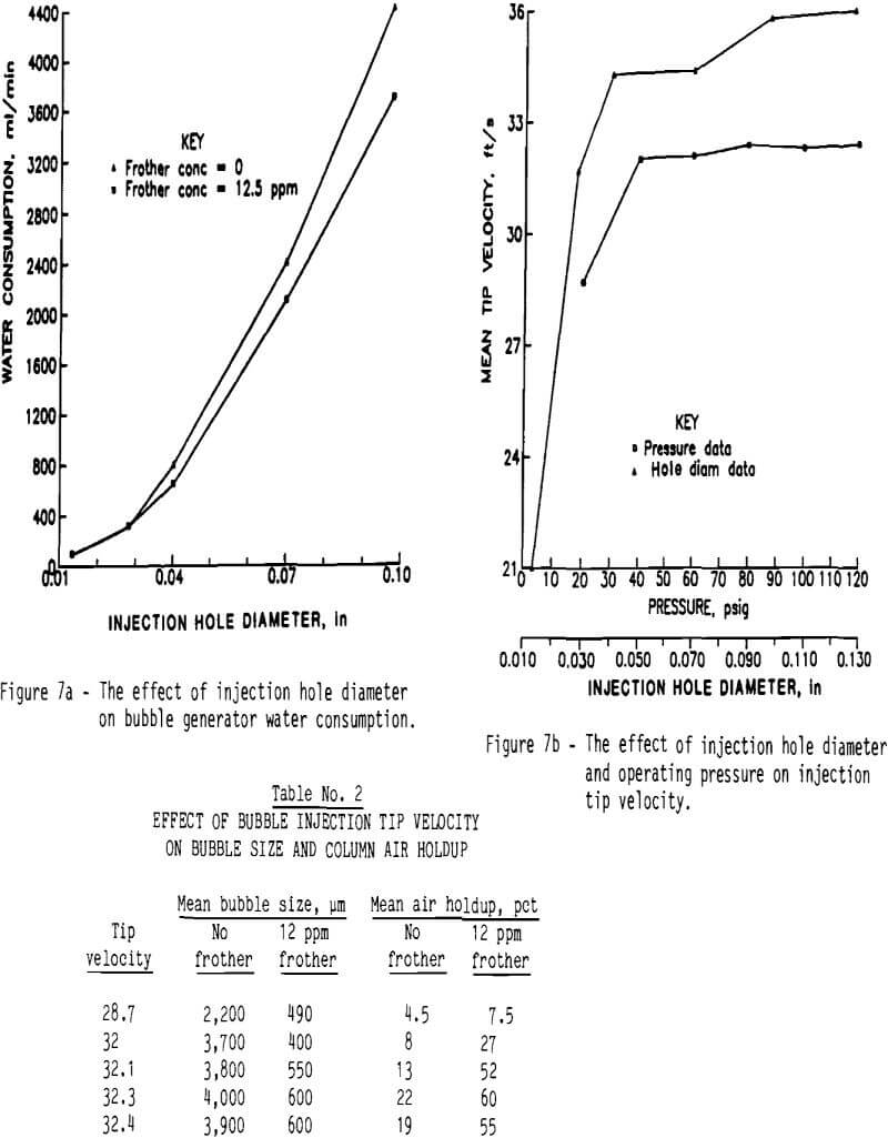
Results indicate that as injection hole size increased, bubble size, air holdup (Figure 5) and water consumption (Figure 7a) increased. Below an injection hole diameter of 0.05 cm (0.02 in), mechanical control of the system was impossible. Although air consumption increased only linearly with injection hole diameter, water consumption increased, as predicted by fluid dynamics, with the square of the hole diameter. Based on these results, an optimum injection hole diameter of 0.1 cm (0.04 in) was chosen.
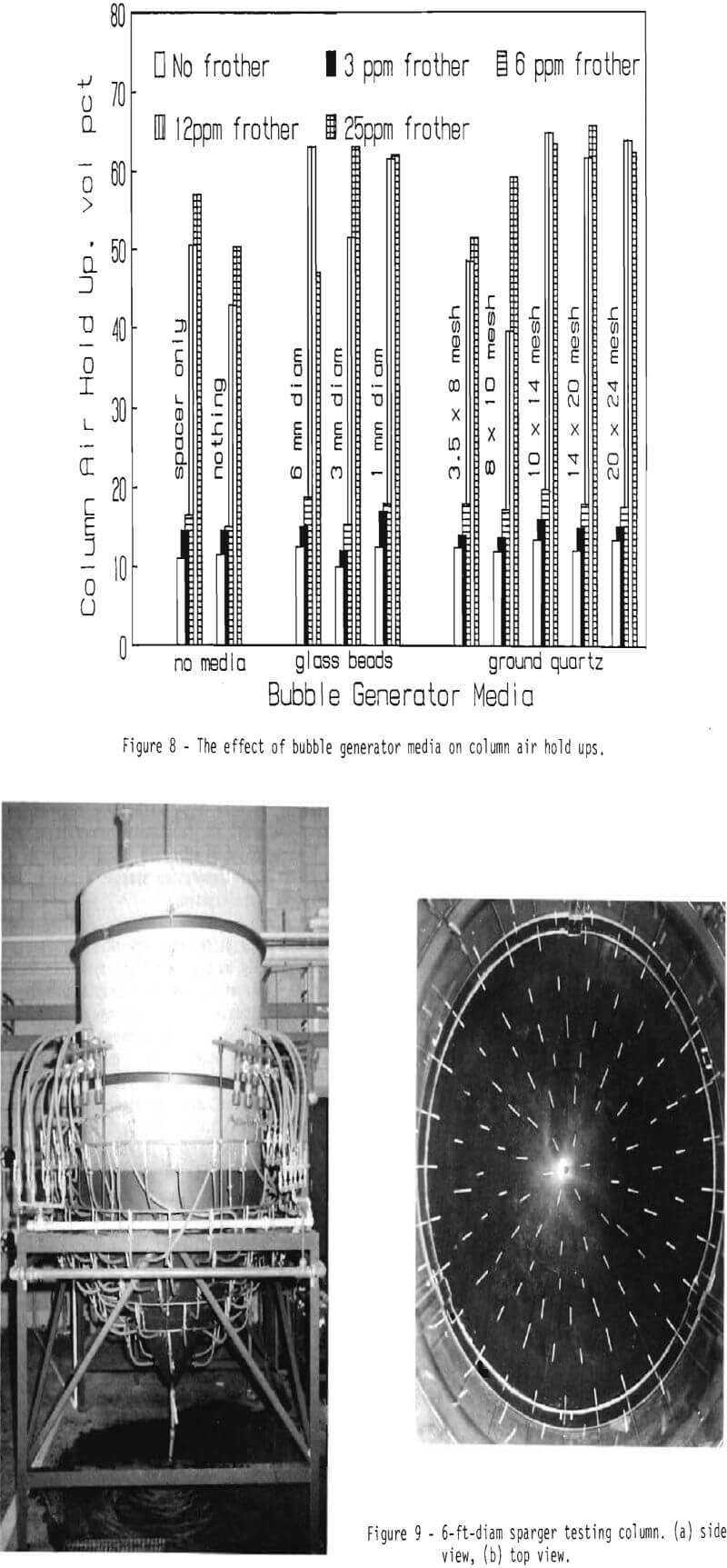
Results shown in Figures 4, 5, 6, and 8 indicate the strong effect of frother (Dowfroth 400) concentration on bubble size and column air holdup. Frother addition lowers the solution surface tension, which permits stable formation of fine bubbles. Results shown in Figure 4 also indicate that the effect on bubble size is greatest up to 12.5 ppm. Above this level, column air holdup increases (Figures 4 and 8) but bubble size decreases only slightly (Figure 4). Tests at the Salt Lake City Research Center have shown that optimum bubble size is dependent on the mineral system involved and is best dealt with on a case-by-case basis.
Results shown in Figure 6 indicate that both air holdup and bubble size increased with increased operating pressure. Also, as the surface tension is reduced by addition of 12.5 ppm Dowfroth 400, bubble size becomes much less sensitive (up to 60 psig) and air holdup becomes much more sensitive to changes in operating pressure than in normal tap water. Therefore, in order to achieve the finest bubble size with an adequate air holdup, a minimum operating pressure of 60 psig was chosen. Adequate air holdup must be evaluated on a case-by-case basis as it affects mineral recovery. Generally, good laboratory results have been achieved with coarse-bubble air holdups in excess of 11 pct and fine-bubble air holdups using greater than 20 pct.
Results presented in Figure 7b indicate that pressure and injection hole diameter have a substantial effect on the tip velocity at which the air-water mixture is released from pressure at the tip. Tip velocity (ft/s) was calculated based on the maximum distance (range) a spray from the tip would reach. This is possible using the kinematic equations for motion which describe projectile trajectories according to acceleration, velocity, and x and y distances. The simplified equation is:
Vo = √Rg/sin 2θ…………………………………………………………………………..(1)
where: R = Range; the distance the spray shoots out from the tip.
g = 9.8 m/s²
θ = The angle from the horizontal at which the spray is released.
This method was chosen for its directness and simplicity and because of the inability to measure the degree to which air was compressed as it passed through the orifice. Results given in Table 2 indicate the need for an adequate tip velocity. Based on these results, a minimum required tip velocity (as measured by the above described technique) of 9.75 m/s (32 ft/s) was chosen.
Results shown in Figure 8 indicate a minimal effect of bubble generator media type, shape, and size on column air holdup. Even without media, the bubble generator achieved good air holdups, however, control of the system was very poor. Control and air holdup improved as contact media size was reduced. The preferred contact medium was chosen as either 1 -mm-diam glass beads or minus 10- plus 24-mesh ground quartz.
Bubble Generator Scaleup
Because of the excellent results that the external bubble generation system achieved on laboratory-scale columns, scaleup to commercial- diameter columns was pursued. As previous testing had indicated that hole size was critical, scaleup required additional injection tips to provide sufficient air (bubbles) for a commercial-diameter column.
Tests were conducted initially on a 0.3-m (1- ft)-diam column to determine the minimum number of injection holes necessary to produce an adequate air holdup without frother, as this would produce the least favorable conditions for bubble generation (i.e., largest bubbles and lowest air holdups). It was also known that it is important to limit the number of holes as the
water addition (consumption) rate increases linearly with the total injection tip hole area.
Results achieved on the 0.3-m (1-ft)-diam column indicated that nine 0.1-cm (0.04-in)-diam injection holes were required to produce a coarse-bubble air holdup of approximately 13 pct. With this number of injection holes, 2-3 L/min of water were required. Bubble size control and mechanical operation of the system were similar to that achieved with a single tip.
Results on the 0.3-m (1-ft)-diam column suggested that a scaleup factor of approximately ten to twelve 0.1-cm (0.04-in)-diam injection holes per square foot of column cross section was adequate. This value was used to design the sparger system for a 0.91-m (3-ft)-diam column. This system consisted of twenty-five 3-hole injection tips located on three elevations on the conical column base connected to three bubble generators via a pipe manifold system.
Test results for this column indicated that an 11.8-pct coarse bubble air holdup could be achieved using twenty 3-hole injection tips with 20 L/min water addition (consumption). This water usage translates to roughly 5 pct of the volumetric feed slurry flow rate that a column of this diameter could process. As testing proceeded, it became apparent from visual observation that bubble dispersion and distribution within the column may vary drastically at different locations and should be considered in sparger evaluation. In order to ensure that this type of sparger provided rapid and uniform bubble dispersion, a short section of 6.35-cm (2.5-in)-diam column was suspended inside the 0.91-m (3-ft)-diam column and ports on it were connected via flexible hose to manometer tubes on the 3-ft-diam column. Air holdups were then determined and compared, and a mean air holdup and standard deviation were calculated. This procedure was performed at several elevations above the sparger tips. The point at which a minimum or constant standard deviation was obtained was chosen as the point at which bubble dispersion or distribution had become uniform.
Testing was performed for both coarse (no frother) and fine (Dowfroth 100 added) bubbles. It was determined that bubble dispersion was uniform within 0.16 m (1.5 ft) above the top sparger ring using coarse bubbles and within 0.15 m (0.5 ft) above the top sparger ring using fine bubbles.
To assure that a design factor of ten to twelve 0.1-cm (0.01-in)-diam injection holes per square foot of column cross section was a valid factor, a 6-ft-diam by 6-ft-tall clear Plexiglas column was constructed with a sparging system consisting of 107 three-hole injection tips connected to 16 external bubble generators with valves and regulators to control the air and water flow and distribution (Figure 9). The injection tips were located on six concentric manifold rings encompassing the conical column base. These manifold rings served to distribute the air-water mixture from the bubble generators to the tips. Dispersion of the air-water mixture became increasingly important as the column diameter increased. Testing on this diameter column indicated that a coarse-bubble air holdup of 11 pct could be achieved with a water injection (consumption) rate of (114 L/min) (roughly 1 pet of the volumetric feed slurry flow rate capacity for a column of this diameter) using 321 0.01-in (0.1-cm) diam injection holes. As with the 0.91-m (3-ft)-diam column, bubble density was visibly different at various locations within the column. Therefore, an evaluation using the same procedure previously discussed was conducted to determine the rapidity with which uniform bubble dispersion was achieved. It was determined that uniform coarse-bubble dispersion was achieved within 0.16 m (1.5 ft) above the top injection tip ring. This rapid dispersion verified that not only was a good air holdup possible using the Bureau’s external bubble generation system, but the quality of the bubble dispersion was good.
Commercial Bubble Generator Design
Because of the economical and logistical problems involved with uniformly distributing a two-phase mixture such as air and water to separate release tips without a separation occurring, and to facilitate retrofitting of filter-bag type spargers to the Bureau’s external bubble generation system, a tube-style design was investigated.
The primary difference between the tip-style and tube-style bubble generation system is that with the tube-style system, multiple injection holes are located along an injection tube, instead of having only one to three holes placed at the end of a single tip. The design for a 0.91-m (3-ft)-diam column tube-style bubble generation system, shown in Figure 10, consists of four 0.64-cm (0.25-in)-ID by a 1.27-cm (0.5- in)-OD stainless steel injection tubes with eighteen to twenty to 20 0.1-cm (0.01-in)-diam injection holes evenly spaced in pairs along the tube lengths shooting downward at 15° angles from the vertical. These tubes are connected via flexible hose to four bubble generators (one per tube) equipped with flow-control valves and quick-disconnect couplings. The bubble generators are connected to main house-air and water lines through a pipe manifold with pressure regulators and flowmeters on both the air and water lines. An oil-coalescing filter on the air line and sediment filter on the water line are recommended to ensure a clean source of air and water to the bubble generation system. The tubes are inserted into the column through column shut-off valves that permit extraction of
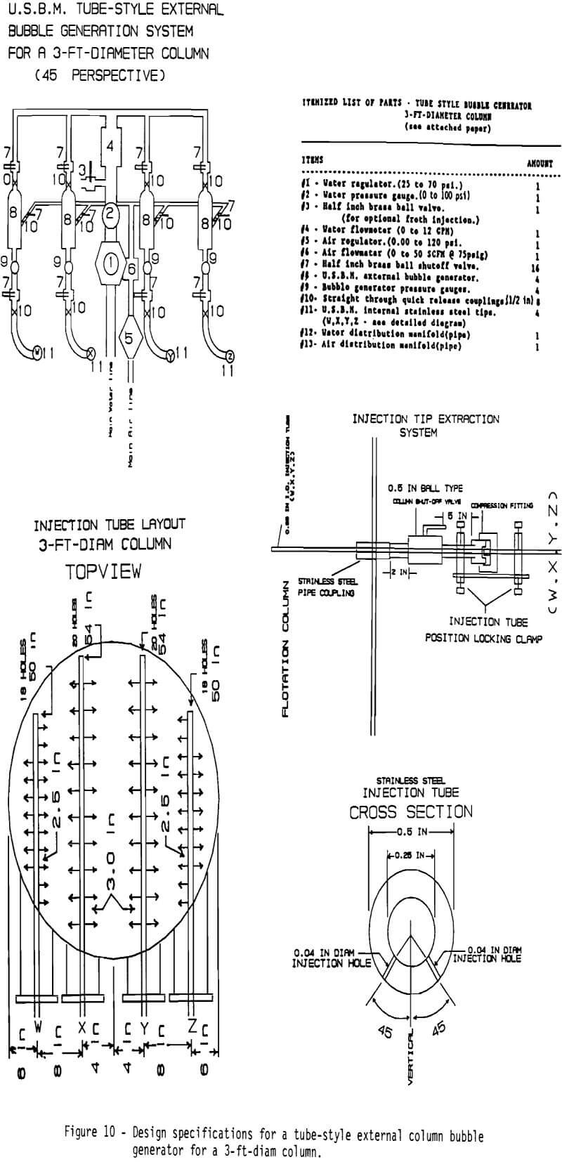
the tubes for maintenance or replacement without column shutdown. Also, ball valves and quick- disconnect couplings make it possible to change a bubble generator in a matter of seconds without significant disruption to the system.
This design effectively replaces a system of twenty-five 3-hole injection tips with four injection tubes and produces equivalent air holdups and bubble size control. Similarly, a tube-style injection system of twenty 0.64-cm (0.25-in)-ID injection tubes for a 6-ft-diam column replaces over one hundred 3-hole injection tips with equivalent capabilities.
Both the tip-style and tube-style external bubble generation systems have been well received by industry and are currently operating on commercial and laboratory columns in the U.S. and Canada.
Potential alternative uses for the external bubble generation system include wastewater treatment, solution aeration to promote oxidation and heat removal, and supercharging of flotation cells.
Summary
In summation, the Bureau has been actively investigating column flotation since 1983. Amenability studies on a wide variety of ores have demonstrated that column flotation has many advantages over conventional flotation and merits application.
Study of mineral behavior within columns has led to a greater understanding of mineral separation phenomena within columns. The parameters that affect column flotation were identified to obtain optimum column performance.
Research led to development of a simple method for externally generating bubbles for a flotation column or other application. This method for generating bubbles is strongly affected by pressure, frother concentration (solution surface tension), injection tip hole size, and tip velocity, and weakly affected by contact media size. This system, which permits extensive bubble size control at enhanced column air holdups compared with conventional porous spargers, has been successfully scaled up for use in commercial flotation columns and is currently being operated in a number of mineral processing plants and mineral beneficiation research laboratories. The system is simple to construct, easy to operate, and allows onstream maintenance.
The Bureau is continuing its efforts to develop and transfer superior technology to the minerals and metallurgical industries.
